
i
i
i
i
i
i
i
i
Chapter 9
Global Illumination
“If it looks like computer graphics,
it is not good computer graphics.”
—Jeremy Birn
Radiance is the final quantity computed by the rendering process. So
far, we have been using the reflectance equation to compute it:
L
o
(p, v)=
Ω
f(l, v) ⊗L
i
(p, l)cosθ
i
dω
i
, (9.1)
where L
o
(p, v) is the outgoing radiance from the surface location p in the
view direction v; Ω is the hemisphere of directions above p; f(l, v)isthe
BRDF evaluated for v and the current incoming direction l; L
i
(p, l)isthe
incoming radiance into p from l; ⊗ is the piecewise vector multiplication
operator (used because both f (l, v)andL
i
(p, l) vary with wavelength, so
are represented as RGB vectors); and θ
i
is the angle between l and the
surface normal n. The integration is over all possible l in Ω.
The reflectance equation is a restricted special case of the full rendering
equation, presented by Kajiya in 1986 [619]. Different forms have been used
for the rendering equation. We will use the following one:
L
o
(p, v)=L
e
(p, v)+
Ω
f(l, v) ⊗ L
o
(r(p, l), −l)cosθ
i
dω
i
, (9.2)
where the new elements are L
e
(p, v) (the emitted radiance from the surface
location p in direction v), and the following replacement:
L
i
(p, l)=L
o
(r(p, l), −l). (9.3)
This replacement means that the incoming radiance into location p from
direction l is equal to the outgoing radiance from some other point in the
opposite direction −l. In this case, the “other point” is defined by the
ray casting function r(p, l). This function returns the location of the first
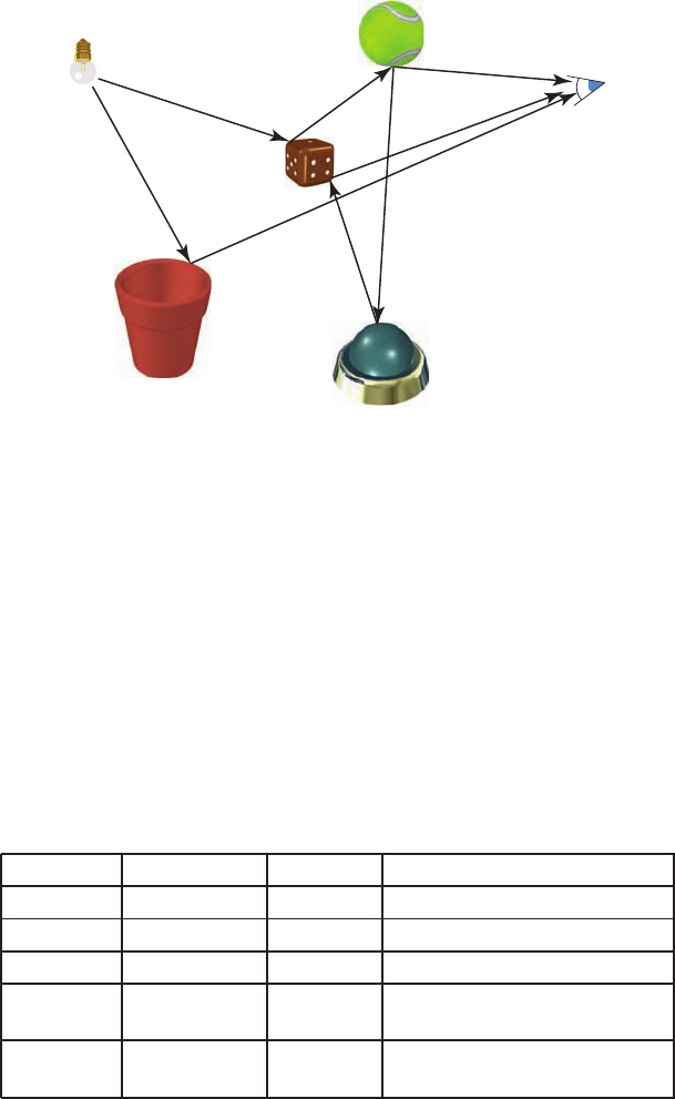
surface point hit by a ray cast from p in direction l (see Figure 9.1).
327

i
i
i
i
i
i
i
i
328 9. Global Illumination
L
i
(p,l)
L
o
(r(p,l),-l)
r(p,l)
p
l
-l
Figure 9.1. The shaded surface location p, lighting direction l, ray casting function
r(p, l), and incoming radiance L
i
(p, l), also represented as L
o
(r(p, l), −l).
The meaning of the rendering equation is straightforward. To shade
a surface location p, we need to know the outgoing radiance L
o
leaving
p in the view direction v. This is equal to the emitted radiance L
e
plus
the reflected radiance. Emission from light sources has been studied in
previous chapters, as has reflectance. Even the ray casting operator is not
as unfamiliar as it may seem. The Z-buffer computes it for rays cast from
the eye into the scene.
The only new term is L
o
(r(p, l), −l), which makes explicit the fact
that the incoming radiance into one point must be outgoing from an-
other point. Unfortunately, this is a recursive term. That is, it is com-
puted by yet another summation over outgoing radiance from locations
r(r(p, l), l
). These in turn need to compute the outgoing radiance from
locations r(r(r(p, l), l
), l
), ad infinitum (and it is amazing that the real
world can compute all this in real-time).
We know this intuitively, that lights illuminate a scene, and the photons
bounce around and at each collision are absorbed, reflected, and refracted
in a variety of ways. The rendering equation is significant in that it sums
up all possible paths in a simple (looking) equation.
In real-time rendering, using just a local lighting model is the default.
That is, only the surface data at the visible point is needed to compute
the lighting. This is a strength of the GPU pipeline, that primitives can
be generated, processed, and then be discarded. Transparency, reflections,
and shadows are examples of global illumination algorithms, in that they
use information from other objects than the one being illuminated. These
effects contribute greatly to increasing the realism in a rendered image, and
also provide cues that help the viewer to understand spatial relationships.
One way to think of the problem of illumination is by the paths the
photons take. In the local lighting model, photons travel from the light
to a surface (ignoring intervening objects), then to the eye. Shadowing
techniques take into account these intervening objects’ direct effects. With
environment mapping, illumination travels from light sources to distant ob-
jects, then to local shiny objects, which mirror-reflect this light to the eye.
Irradiance maps simulate the photons again, which first travel to distant
i
i
i
i
i
i
i
i
329
LSDE
LSDSSE
LDE
L
E
D
D
S
S
Figure 9.2. Some paths and their equivalent notation.
objects, but then light from all these objects is weighted and summed to
compute the effect on the diffuse surface, which in turn is seen by the eye.
Thinking about the different types and combinations of light transport
paths in a more formal manner is helpful in understanding the various algo-
rithms that exist, and where further research may yield the most benefit.
Heckbert [519] has a notational scheme that is useful for describing the
paths simulated by a technique. Each interaction of a photon along its trip
from the light (L)totheeye(E) can be labeled as diffuse (D) or specular
(S). Categorization can be taken further by adding other surface types,
such as “glossy,” meaning shiny but not mirror-like. Figure 9.2 shows some
paths and the equivalent notation. Algorithms can be briefly summarized
Operator Description Example Explanation
∗ zero or more S∗ zero or more specular bounces
+ one or more D+ one or more diffuse bounces
? zero or one S? zero or one specular bounces
| either/or D|SS either a diffuse or two specular
bounces
() group (D|S)∗ zero or more of diffuse or spec-
ular
Table 9.1. Regular expression notation.
i
i
i
i
i
i
i
i
330 9. Global Illumination
by regular expressions, showing what types of interactions they simulate.
See Table 9.1 for a summary of basic notation.
Photons can take various paths from light to eye. The simplest path is
LE, where a light is seen directly by the eye. A basic Z-buffer is L(D|S)E,
or equivalently, LDE|LSE. Photons leave the light, reach a diffuse or
specular surface, and then arrive at the eye. Note that with a basic ren-
dering system, point lights have no physical representation. Giving lights
geometry would yield a system L(D|S)?E,inwhichlightcanalsothengo
directly to the eye.
If environment mapping is added to the renderer, a compact expression
is a little less obvious. Though Heckbert’s notation reads from light to
eye, it is often easier to build up expressions going the other direction.
The eye will first see a specular or diffuse surface, (S|D)E.Ifthesurface
is specular, it could also then, optionally, reflect a (distant) specular or
diffuse surface that was rendered into the environment map. So there is an
additional potential path: ((S|D)?S|D)E. To count in the path where the
eye directly sees the light, add in a ? to this central expression to make it
optional, and cap with the light itself: L((S|D)?S|D)?E.
1
Note that this expression could be expanded to LE|LSE|LDE|LSSE|
LDSE, which shows all the possible paths individually, or the shorter
L((D|S)?S?E. Each has its uses in understand relationships and limits.
Part of the utility of the notation is in expressing algorithm effects and
being able to build off of them. For example, L(S|D) is what is encoded
when an environment map is generated, and SE isthepartthatthen
accesses this map.
As various global algorithms are introduced in this chapter, their no-
tational equivalent will be presented. The rendering equation itself can be
summarized by the simple expression L(D|S) ∗ E, i.e., photons from the
light can hit zero to nearly infinite numbers of diffuse or specular surfaces
before reaching the eye.
Global illumination research focuses on methods for efficiently comput-
ing light transport along some of these paths. Determining whether light
reaches a surface is one of the most critical factors, and this chapter be-
gins in this area, discussing shadows and ambient occlusion. A variety of
techniques to perform global reflection, refraction, caustics, and subsurface
scattering follow. Two basic alternate rendering algorithms, radiosity and
ray tracing, are then briefly described.
One of the most common uses of full global illumination algorithms in
real-time rendering is to compute various quantities ahead of time, which
are later used to accelerate the rendering process or improve its quality.
1
When building up such paths from the eye, it is often easier on the brain to reverse
the order of the notation, e.g., E(D|S(S|D)?)?L. Either direction is fine; this notation
is meant as a tool, not as an exercise in confusion.

i
i
i
i
i
i
i
i
9.1. Shadows 331
The chapter ends with a discussion of the various quantities that can be
precomputed and used in this manner.
9.1 Shadows
Shadows are important elements in creating realistic images and in provid-
ing the user with visual cues about object placement. Here we will present
the most important and popular real-time algorithms for dynamic shadows
and briefly survey the rest as they apply to the themes developed. Various
shadow techniques can usually be mixed as desired in order to maintain
quality while still being efficient.
The terminology used throughout this section is illustrated in Fig-
ure 9.3, where occluders are objects that cast shadows onto receivers.Point
light sources generate only fully shadowed regions, sometimes called hard
shadows. If area or volume light sources are used, then soft shadows are
produced. Each shadow can then have a fully shadowed region, called the
umbra, and a partially shadowed region, called the penumbra. Soft shadows
are recognized by their soft shadow edges. However, it is important to note
that they usually cannot be rendered correctly by just blurring the edges
of a hard shadow with a low-pass filter. As can be seen in Figure 9.4, a
correct soft shadow is sharper the closer the shadow casting geometry is
to the receiver. The umbra region of a soft shadow is not equivalent to a
hard shadow generated by a point light source. Instead, the umbra region
of a soft shadow decreases in size as the light source grows larger, and in
fact, it might even disappear, given a large enough light source and a re-
ceiver far enough from the occluder. Soft shadows are generally preferable
because the soft edges let the viewer know that the shadow is indeed a
=
+
Figure 9.3. Shadow terminology: light source, occluder, receiver, shadow, umbra, and
penumbra.
..................Content has been hidden....................
You can't read the all page of ebook, please click here login for view all page.