

i
i
i
i
i
i
i
i
342 9. Global Illumination
+1
+1
+1
+1
+1
+1
-1
Figure 9.11. A two-dimensional side view of counting shadow volume crossings using
two different counting methods. In z-pass volume counting, the count is incremented
as a ray passes through a frontfacing polygon of a shadow volume and decremented on
leaving through a backfacing polygon. So at point A,therayenterstwoshadowvolumes
for +2, then leaves two volumes, leaving a net count of zero, so the point is in light. In
z-fail volume counting, the count starts beyond the surface (these counts are shown in
italics). For the ray at point B,thez-pass method gives a +2 count by passing through
two frontfacing polygons, and the z-fail gives the same count by passing through two
backfacing polygons. Point C shows the importance of capping. The ray starting from
point C first hits a frontfacing polygon, giving −1. It then exits two shadow volumes
(through their endcaps, necessary for this method to work properly), giving a net count
of +1. The count is not zero, so the point is in shadow. Both methods always give the
same count results for all points on the viewed surfaces.
buffer holds the state of shadowing for every pixel. Finally, the whole scene
is rendered again, this time with only the diffuse and specular components
of the materials active, and displayed only where the value in the stencil
buffer is 0. A value of 0 indicates that the ray has gone out of shadow
as many times as it has gone into a shadow volume—i.e., this location is
illuminated by the light.
The stencil buffer itself is not required for this method. Roettger et
al. [1075] discuss a number of strategies for using the color and alpha buffers
to take the place of the stencil buffer, and they obtain comparable perfor-
mance. On most GPUs it is possible to do a signed addition to the frame
buffer. This allows the separate frontfacing and backfacing passes to be
performed in a single pass.
The separate frontface and backface passes can also be combined into
one pass if shadow volumes are guaranteed to not overlap. In this case, the
stencil buffer is toggled on and off for all shadow volume faces rendered.
In the final pass, if the stencil bit is on, then the surface is in shadow.
i
i
i
i
i
i
i
i
9.1. Shadows 343
The general algorithm has to be adjusted if the viewer is inside a shadow
volume, as this condition throws off the count. In this case, a value of 0
does not mean a point is in the light. For this condition, the stencil buffer
should be cleared to the number of shadow volumes the viewer starts inside
(instead of 0). Another more serious problem is that the near plane of
the viewer’s viewing frustum might intersect one or more shadow volume
planes. If uncorrected, this case invalidates the count for a portion of the
image. This problem cannot be cured by simple count adjustment. The
traditional method to solve this problem is to perform some form of capping
at the near plane [84, 653, 849]. Capping is where additional polygons are
drawn so as to make the object appear solid. However, such methods are
generally not robust and general.
Bilodeau and Songy [87] were the first to present (and patent) an al-
ternate approach to avoid this near plane clipping problem; Carmack also
independently discovered a similar technique [653] (see Hornus et al. [568]
for the differences). Nonintuitive as it sounds, the idea is to render the
shadow volumes that are obscured by visible surfaces. The first stencil
buffer pass becomes: Render the backfacing shadow volume polygons and
increment the stencil count when the polygon is equal to or farther than the
stored z-depth. In the next stencil pass, render the frontfacing shadow vol-
ume polygons and decrement the count when the polygon is, again, equal
to or farther than the stored z-depth. Because the shadow volumes are
drawn only when the Z-buffer test has failed, they are sometimes called
z-fail shadow volumes,versusz-pass. The other passes are done as be-
fore. In the original algorithm, a point is in shadow because the number
of frontfacing polygons crossed was larger than the number of backfacing
polygons; in this version, the object is in shadow if the number of back-
facing polygons not seen is larger than the number of frontfacing polygons
not seen, something of a logical equivalent. The difference is that now all
shadow volume polygons in front of surfaces, including those that could
encompass the viewer, are not rendered, so avoiding most viewer location
problems. See Figure 9.11.
For the z-pass algorithm, the original triangles generating the quadri-
laterals do not actually need to be rendered to the stencil buffer. These
polygons are always made invisible by the first pass, which will set z-depths
such that these polygons will match and so not be rendered. This is not the
case for the z-fail algorithm. To properly maintain the count, these origi-
nating polygons must be rendered. In addition, the shadow volumes must
be closed up at their far ends, and these far endcaps must be inside the far
plane. The z-fail algorithm has the inverse of the problem that the z-pass
has. In z-pass, it is possible for shadow volumes to penetrate the view
frustum’s near plane; in z-fail, shadow volumes can potentially penetrate
the far plane and cause serious shadowing errors. See Figure 9.12.
i
i
i
i
i
i
i
i
344 9. Global Illumination
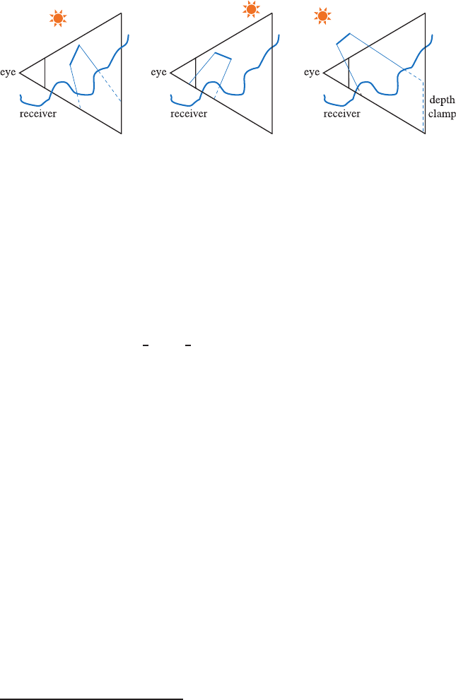
Figure 9.12. The z-pass and z-fail shadow volume methods; z-pass is shown as solid lines
emanating from the occluder, z-fail as dashed lines beyond the receiver. On the left,
if the z-fail method were used for the case shown, the shadow volume would need to
be capped before reaching the far plane. In the middle, z-pass would give an incorrect
count, as it penetrates the near plane. On the right, neither method can work without
some way to avoid the clip by either the near or far plane; depth clamping’s effect is
shown on z-fail.
Everitt and Kilgard [326] present two simple, robust solutions to this
problem, one implemented in hardware and the other in software. In hard-
ware, the solution is called depth clamping. Beginning with the GeForce3,
NVIDIA added the NV
depth clamp extension. What this does is to no
longer clip objects to the far view plane, but rather to force all objects
that would normally be clipped away by the far plane to instead be drawn
on the far plane with a maximum z-depth. This extension was introduced
specifically to solve the z-fail shadow volume capping problem automati-
cally. The edge and capping polygons can be projected out an arbitrarily
far distance and will be properly handled by hardware. With this addition,
z-fail shadow volumes become a simple and robust way to generate hard
shadows. The only drawback (besides hardware dependence)
3
is that in
some cases, the z-pass will fill less pixels overall, so always using z-fail with
depth clamping may be slower.
Their software solution elegantly uses some of the lesser-known prop-
erties of homogeneous coordinates. Normally, positions are represented as
p =(p
x
,p
y
,p
z
, 1) in homogeneous coordinates. When the fourth compo-
nent, w, is 0, the resulting coordinate (p
x
,p
y
,p
z
, 0) is normally thought of
as a vector. See Section A.4. However, w = 0 can also be thought of as
a point “at infinity” in a given direction. It is perfectly valid to think of
points at infinity in this way, and this is, in fact, used as a matter of course
in environment mapping. The assumption in EM is that the environment is
far enough away to access with just a vector, and for this to work perfectly,
the environment should be infinitely far away.
3
This functionality might be emulated on non-NVIDIA hardware by using a pixel
shader program.
i
i
i
i
i
i
i
i
9.1. Shadows 345
When a shadow is cast by an object, the shadow volume planes extend
toward infinity. In practice, they are usually extended some large, finite
distance, but this limitation is not necessary. Given a shadow volume edge
formed by v
0
and v
1
and a light at l, the direction vectors v
0
− l and
v
1
−l can be treated as the two other points (that is, with w =0)forming
a quadrilateral side of the shadow volume. The GPU works with such
points just fine, transforming and clipping the object to the view frustum.
Similarly, the far cap of the shadow volume for z-fail can be generated by
projecting the triangle out to infinity.
Doing this procedure does not solve anything in and of itself, as the far
plane still will clip the shadow volume, and so the z-fail method will not
work. The other, key part of the software solution is to set the far plane
itself to infinity. In Section 4.6.2, about projection matrices, the near and
far planes are finite, positive numbers. In the limit as the far plane is taken
to infinity, Equation 4.68 on page 95 for the projection matrix becomes
P
p
=
⎛
⎜
⎜
⎜
⎜
⎜
⎝
2n
r − l
0 −
r + l
r − l
0
0
2n
t − b
−
t + b
t − b
0
00 1−2n
00 1 0
⎞
⎟
⎟
⎟
⎟
⎟
⎠
. (9.8)
Setting the far plane number to infinity loses surprisingly little precision
normally. Say the near plane is 1 meter away and the far plane is 20, and
these map to [−1, 1] in z-depth. Moving the far plane to infinity would map
the 1-to-20-meter range to [−1, 0.9], with the z-depth values from 20 meters
to infinity mapped to [0.9, 1]. The amount of numerical range lost between
the near plane, n, and the original far plane, f , turns out to be only n/f.
In other words, when the distance to the far plane is significantly greater
than to the near plane (which is often the case), moving the far plane to
infinity has little overall effect on precision.
The z-fail method will work with the far plane at infinity. The triangle
closing the shadow volume at infinity will be properly rendered, and nothing
will be clipped against the far plane. For directional lights (i.e., those also
“at infinity”) the two quadrilateral points at infinity are even easier to
compute: They are always equal to the direction from the light. This
has the interesting effect that all the points at infinity from directional
lights are the same point. For this case, the side quadrilaterals actually
become triangles, and no cap at infinity is necessary. Both Lengyel [759]
and McGuire [843] discuss implementation details in depth, as well as a
number of other optimizations. Kwoon [705] also has an extremely detailed
presentation on the subject.

i
i
i
i
i
i
i
i
346 9. Global Illumination
An example of the shadows that the shadow volume algorithm generates
is shown in Figure 9.13. As can be seen in the analysis image, an area
of concern is the explosion in the number of polygons rendered, and the
corresponding amount of fill rate consumed. Each triangle and each light
create three additional quadrilaterals that must be properly extended and
rendered into the stencil buffer. For solid occluders, only the set of polygons
facing toward (or the set facing away from) the light needs to be used
to create shadow volumes. The z-pass method usually performs faster
than z-fail, so it should be used when the viewer is known to not be in
shadow [1220]. Hornus et al. [568] present a method that first efficiently
tests where the eye’s near plane is in shadow, so it then can properly
initialize the state and always use z-pass.
Figure 9.13. Shadow volumes. On the left, a character casts a shadow. On the right,
the extruded triangles of the model are shown. Below, the number of times a pixel is
drawn from the extruded triangles. (Images from Microsoft SDK [261] sample “Shad-
owVolume.”)
..................Content has been hidden....................
You can't read the all page of ebook, please click here login for view all page.