
Build a full programmable robot in a few hours for under $100 By Frits Lyneborg, aka “fritsl”

Figure A: Look, it’s your first robot. Isn’t he cute?
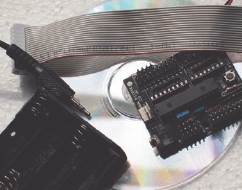
Figure B: The PICAXE-28X1 Starter Pack
This is a walkthrough of how to build a programmable, autonomous (i.e., not remote-controlled, not strictly pre-programmed, but reacting to its surroundings) robot in a few hours. It’s surprisingly easy and doesn’t involve advanced knowledge of electronics to get started. You will have to stay focused as we cover the basics here and a few things will be foreign to you at first. This is meant to be an eye-opening, learn by exploring, project. After building this, you’ll be able to build and control all sorts of electronic devices! Sound crazy? It’s true, you just need to try it to understand how much power is contained in some of the chips you can buy for a few bucks these days. Welcome to the wonderful world of microcontrollers!
The programming examples I show in the end are to make this robot “wall avoiding” (i.e., it will sniff around and explore based on which objects it meets, what is on the left, right, and ahead of it). But it can be programmed to do all sorts of things—easily. If interest is shown, I will provide more programs for it.
1. Buy the materials (project board, microcontroller, and starter pack)
Shopping list:
A PICAXE-28X1 Starter Pack
The 28-pin project board in this package is like a game of Mario Bros; fun and full of extras and hidden features, making you want to play with it over and over again. This includes the main brain, the PICAXE-28X1. At around $40, this is the most expensive part, but you’re buying a computer, and it includes a lot of nice, useful stuff. You get a CD-ROM with lots of manuals on it, cables, a project board, and the microcontroller itself. Actually, it’s cheap for all you get. Be sure to get the USB-version—images in online stores often show a serial-cable version, though they’re selling the USB. When buying the USB-version, it is not necessary to also get the USB cable as an extra item. Once you have this Starter Kit, you just have to buy a new board and microcontroller for future projects—much cheaper.
Note: A version II with cool code can be found at letsmakerobots.com. If you have any problems or questions regarding this project, please feel free to contact me. There are also videos of this project available on its Instructables page.

Figure C: The venerable L293D Motor Driver

Figure D: A servo motor (left), header pins (top right), and a DIL resistor chip (bottom right)
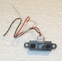
Figure E: The GP2D120 IR sensor
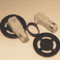
Figure F: Gear motors, wheels, and tires
An L293D Motor Driver
The name says it all, more about this chip later :-)
A PICAXE Servo Upgrade Pack
This is an easy way to get a servo topped with some small parts needed for this project. You can also get any standard servo, a row of header pins (shown in Figure D), and a single 330Ω resistor instead of the DIL Resistor chip that comes with the Servo pack, if you wish.
What is a servo?
A servo is a cornerstone in most robotic applications. It is basically a little motor and gearbox with wires to it, and an axle that can turn some 200 degrees. On this axle you can mount variousshaped “servo horns” onto which things you want to control can be attached. There are three wires on a servo: two for power, and one for signal. The signalwire goes to the device that controls the servo, in this case, our microcontroller. The result is that the microcontroller can decide where exactly the axle should turn and position itself. This is pretty handy, as you can program something to physically move to a precise position.
A Sharp GP2D120 IR sensor—11.5"/Analog
An IR Sensor in the 11.5" range will do. Do not buy the “digital version” of the Sharp sensor for this kind of project. They do not measure distance as the analog ones does. Be sure to get the red/black/white connection wires for it. These are not always included, and it’s a non-standard connector!
I usually use ultrasonic sensors, such as the SRF05 (find it anywhere via Google). The SRF05 is much more reliable and precise than the GP2D120 IR Sensor. It is also faster, but costs a little more, is a little more complicated to write code for, and a little more complex to install—so it is not used here for beginners. If you go for the SRF05, I’ve made a small walkthrough to connecting the SRF05 on letsmakerobots.com/node/66.
Two gear motors with wheels
The higher the gear ratio, the stronger the robot; the lower, the faster the robot. I recommend a ratio somewhere between 120:1 to 210:1 for this kind of a project.
2. You will also need:
![]() Double-sided adhesive tape (for mounting, the foamy kind is best)
Double-sided adhesive tape (for mounting, the foamy kind is best)
![]() Some wire
Some wire
![]() Ordinary adhesive tape (to isolate a cable perhaps)
Ordinary adhesive tape (to isolate a cable perhaps)
![]() Simple soldering equipment (any cheap kit will do)
Simple soldering equipment (any cheap kit will do)
![]() An ordinary small nipper or scissors to cut things
An ordinary small nipper or scissors to cut things
![]() A screwdriver or multitool
A screwdriver or multitool
You could also get (while you’re at it):
![]() Some LEDs, if you want your robot to be able to signal to the world or make cool flashing-effects
Some LEDs, if you want your robot to be able to signal to the world or make cool flashing-effects
![]() More servos to make your robot move more… er… arms?
More servos to make your robot move more… er… arms?
![]() A tiny speaker if you’d like your robot to produce sound-effects and communicate with you
A tiny speaker if you’d like your robot to produce sound-effects and communicate with you
![]() Some sort of tank-track system. Robots with tank tracks are way cool, and the controller and the rest can be the same. Tamiya makes cool tank-track-systems.
Some sort of tank-track system. Robots with tank tracks are way cool, and the controller and the rest can be the same. Tamiya makes cool tank-track-systems.
![]() Any kind of line-sensor kit, to turn your robot into a Sumo, a line-follower, stop it from driving off tables, anything else that needs “a look down”
Any kind of line-sensor kit, to turn your robot into a Sumo, a line-follower, stop it from driving off tables, anything else that needs “a look down”
Figure G: Attaching the wheels
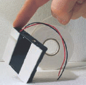
Figure H: Using doublesided tape to attach the battery holder
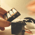
Figure I: Assembling the main components using the battery holder as the “body”
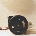
Figure J: Side view with wheels, servo, gearmotors, and battery holder assembled together
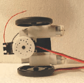
Figure K: Top view of servo, looking down on "servo horn” disk in center
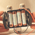
Figure L: Bottom view, showing battery pack

Figure M: The PICAXE project board

Figure N: Installing the 330Ω DIL (or Dual InLine) resistor (the yellow chip)
3. Okay, let’s make a robot!
You’ve ordered the stuff, received your package(s), and now you want to build. Let’s get started!
First, mount the wheels to your geared motors. Add tires (rubber bands in this case) (Figure G). batteries, servo, motors, and wheels. Make sure the wheels and servo can turn freely, and it can stand on its wheels (Figures J–L).
4. The double-sided adhesive tape trick
An easy way to mount stuff for fast (and amazingly solid and lasting) robots is double-sided adhesive tape (see Figure H).
5. Build the body out of…nothing. Really!
Insert the batteries, so you have a realistic idea of weight and balance. With the batteries below the axle of the wheels, you can make it balanced, but it’s no problem if it’s not exactly balanced. Just make sure that if anything drags the ground, it is behind the wheel axles. Add some double-stick tape to the bottom of the servo as well.
6. Design your robot
Choose your own design, you can also add extra materials if my “design” is too simple. The main thing is that we have it all glued/taped together: batteries, servo, motors, and wheels. Make sure the wheels and servo can turn freely, and it can stand on its wheels (Figures J–L).
7. Disconnect!
Take out the batteries, to avoid burning something unintended! They were just a test load.
8. Get started with the board
You should have a project board similar to the one in Figure M. Notice that it has a chip in it. Take it out. That chip is called a Darlington Driver. It’s quite handy there on the board, but we’ll not need it for this project, and we need its socket space, so away with the chip! It is easiest to get chips out of their sockets by inserting a small, flat screwdriver just below the chip, rocking it gently, and tipping it up carefully. Don’t bend the pins!
9. Insert the chips
A fresh, brand new chip usually does not fit into a socket without some adjusting. Place the chip on one side, so that a row of its pins is flat, on hard, level surface, and gently bend all its legs (pins) slightly inward, applying the same pressure along all the pins. Keep doing this on both rows of pins, checking against the socket on the board, until all pins line up with the holes on the chip socket and it can easily be pressed in. Take your time as the pins can easily snap off.
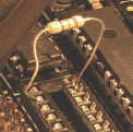
Figure O: Using a single 330Ω resistor
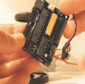
Figure P: The PICAXE28X1 microcontroller chip installed. Brains, baby!

Figure Q: Plastic left over from the manufacturing process. Remove.

Figure R: Wiring up the two gearmotors
Make sure all the pins are firmly in the sockets.
If you bought the Servo Upgrade from PICAXE, you have a yellow chip. Put it in the socket in place of the Darlington (Figure N). This yellow chip is actually called a DIL (or Dual InLine) Resistor. It is really eight 330Ω resistors in a neat IC package. If you happen to have a single resistor, you can insert it instead, in the slot numbered “0” (see Figure O), as this is the only one we’ll actually use for our single servo. Insert the large chip, the brains, the big daddy o’ IC, the microcontroller—our PICAXE 28—into the project board (see the 28-pin chip in Figure P). It is important to put this in the correct way. There’s a little dot, called a dimple, on one end of the chip, and also a corresponding one on the project board. They must go together. This chip will get power from the board via two of its pins. All the remaining 26 pins are connected around elsewhere on the board, and they will be programmable for you, so you can send current in and out to detect things and control things with the programs you upload into your microcontroller. (Cool!)
10. Insert the motor controller
Insert the L293D motor controller into the last socket (Figure P). Be sure to install this the right way just as with the microcontroller.
The L293D motor controller will take four of the outputs from the microcontroller and turn them into two. Sound silly? Well, any ordinary output from the microcontroller can only be “on” or “off.” So just using these would only make your robot able to drive forward or stop. No reverse! And reverse comes in handy when facing a wall. The board is so smart that the two (now reversible) outputs get their own space, marked (A) and (B), next to the motor controller. More about this later.
11. The red plastic on the back of the board
On the backside of the board, you may find some strange plastic strips. These have no use, they’re left over from the manufacturing process. They “dip” the boards in warm tin (yum!), and parts they do not want tinned are sealed with this plastic material. Just peal it off when you need the holes they cover.
12. Connect the motors’ wires to the board
Take four pieces of wire and solder them to the four holes on the board marked “A & B”. Alternately, you can use some other means of connecting the cables—you can buy all sorts of standard plugs and pins that’ll fit. But if you’re like me, just solder them onto the board. You can strengthen them with tape or use heat-shrinking tubing to support the wires (Figures R-S).
13. Connect the wires to the motors
The two “As” go to one motor, and the two “Bs” to the other. It doesn’t matter which is which, as long as “A” is connected to one motor, and “B” to the two poles of the other. (And yes, I know, my soldering iron is really, really dirty. Hey, as long as it works, you know?) (Figure T)
14. Hooking up the servo
Now let’s hook up the servo. If you read the PICAXE documentation, you will see that you’re supposed to use two different power sources (one for the microcontroller and one for the servos). For our purpose, and this is a simple robot, I think a single source is fine.
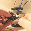
Figure S: Using heat-shrink tubing to neatly bundle the motor wires
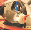
Figure T: Soldering up the motor wires to the terminals on the gearmotors
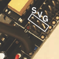
Figure U: Location of servo motor pins, showing S (signal), V (voltage), G (ground)

Figure V: The three servo wires hooked up
You will need to solder an extra pin to output “0”, if you want to use the standard servo connection. Such a pin comes with the PICAXE Upgrade pack—you only need one for one servo, and they can be bought in any electronics store. If your servo’s cable is (black, red, white) or (black, red, yellow), the black should go to the edge of the board. Mine was (brown, red, orange), and so the brown goes to the edge.
Red is the power and usually referred to as V (or V+, +, V1, V2). The black (or brown in my case) is G (or Ground, GND, “-”). So we have our two poles, positive and negative, voltage and ground. Remember your physics lessons? The last color is the “signal,” the electronic pulses that control the movement of the servo shaft and tell it where to go. This wire is usually white, yellow, or orange. A servo needs both (+) and (-) or (V) and (G), and a signal (Figures U and V).
Some other devices you’ll attach to your board may only need “Ground” and “Signal” (G and V), and some may need V, G, as well as Input and Output. This can all be confusing in the beginning, and too often, things are named differently. But after a while, you’ll start to see the logic behind it all. It’s actually rather simple—even I get it!
15. Hooking up the head
Now let’s hook up our Sharp IR sensor (or the SRF05, if you went for that option). If you bought an SRF005, or similar, check out letsmakerobots.com/node/66 for details on how to hook up this sensor, as it’s different than the Sharp.
There are many different ways of hooking up the Sharp IR sensor. Following are the basics of what you need to know:
![]() Red needs to be connected to V1, that’s (in this setup) anything marked “V” or is connected to this
Red needs to be connected to V1, that’s (in this setup) anything marked “V” or is connected to this
![]() Black goes to G, anywhere on the board
Black goes to G, anywhere on the board
![]() White is to be connected to Analog Input 1
White is to be connected to Analog Input 1
If you read the documentation that comes with the project-board, you can find out how to attach the accompanying ribbon cable and use it.
What I’ve done in Figure W is cut off a cable from an old burned-out servo, soldered in a pin, and connected the whole thing just as with a servo. You can use it to see which colors of the Sharp go to which row on the board, or at least one way to do this (Figures W-X).
Whether you use the ribbon cable or my method of connecting the Sharp IR, you should also connect the three remaining analog inputs to V (look at the little pins connected in Figure X, next to the plug). I had some jumper blocks lying around, and you can see that all three leftover analog pin connections are shorted (connected V to G). The last pair, not shorted, are just two “ground” pins, not Inputs. No need to bother with these. If you use the ribbon, you can connect the inputs to V (or ground, for that matter) by connecting the wires in pairs. The reason it’s important to shortcut the unused analog inputs is that they are otherwise left “floating.” This means that you will get all sorts of weird readings on your sensor(s) if these unused Input pins are left open and with no input signals on them.
16. Let there be life!
You now need to get the red wire from your battery’s (+) hooked up to the red wire on the microcontroller board’s (V). And the black wire (-) to the (G) on the board. How you do this depends on the equipment you bought. If there’s a battery connector on both the battery pack and the board, you should still make sure that the “+” from the batteries ends up to the “V” on the board and the negative to the common ground (-) on the board. Make sure these are wired correctly, or you’ll see melting components and smoke! Do not feed the board with more than 6V (no 9V batteries, even though the clip fits one!).

Figure W: The IR sensor hooked up to analog Input 1

Figure X: The other analog inputs are jumpered (shorted) so that they don’t interfere with the IR signal
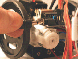
Figure Y: Plugging in the serial jack so the fun can truly begin
Note: Remember, we are only working with one power supply here. You will need to use the same ground (there always must be a common ground), but you’ll use both V1 and V2 power pins. That way, your logic chips will get one source, and your motors another (higher) voltage source.
Install the PICAXE Program Editor on a PC (follow the manual for proper installation and to get your USB, serial, whatever, connection set up). Insert the batteries into your (still “headless”) robot, insert the computer programming cable into your robot. Enter the Program Editor on your PC and write:
servo 0, 150
Press F5
Wait for the program to transfer to the bot, and your servo to give a little twitch.
If something goes wrong here, check troubleshooting in your manuals, check comm ports, etc., until no errors are reported, and all seems to be working. If need be, contact me via this project’s Instructable page.
To test the bot further, write:
servo 0, 200
Press F5
The servo’s servo horn disk should spin a little and stop. To turn the servo back, write:
servo 0, 150
Press F5
Now your robot’s “neck” is facing forward, and you can stick on the Sharp IR sensor (or SRF05 if you went for that).
17. Heads up and go!
You’re done with the basics. You’ve just built yourself a programmable robot. Now the fun starts. You can program your bot to do almost anything, and attach anything to it, expand it in all sorts of creative ways. I’m sure you’re already full of ideas.
A basic control program, code for making your robot sound off, and cool ideas for other ways your robot can be programmed can be found at this project’s Instructables page and at letsmakerobots.com/node/254.
Frits Lyneborg (aka “fritsl”) was born in Denmark in 1970. He is a freelance inventor and developer of toys and robots and is world-famous for projects like “Robot Wall Racers” and the “Yellow Drum Machine” series. Visit fritsl online at letsmakerobots.com/user/4 or via email at [email protected].