
How to Make an OAWR (Obstacle Avoiding Walking Robot)
Build a no-solder robot that can navigate a space without the need of a computer brain By Clement Fletcher

Figure A: The finished OAWR about to explore its environs
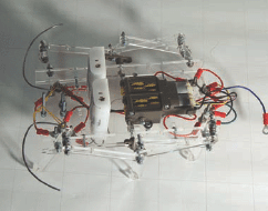
Figure B: A top view with a good look at the Tamiya Twin Motor Gearbox Kit
This Instructable shows you how to make a little walking robot that avoids obstacles (much like many commercially available bots). But what’s the fun in buying a pre-made toy, when you can start with a motor, a sheet of plastic, and a pile of bolts and wires and proceed to make your own!
Features:
![]() Not difficult to source parts (no switches, relays, or computer chips, everything but the motor is available at Home Depot)
Not difficult to source parts (no switches, relays, or computer chips, everything but the motor is available at Home Depot)
![]() No soldering
No soldering
![]() Has a Mechano for grown-ups feel
Has a Mechano for grown-ups feel
![]() Choice of options for cutting out the pieces (scroll saw and drill, access to a laser cutter, purchasing parts online from Ponoko—http://tinyurl.com/6ehwsg)
Choice of options for cutting out the pieces (scroll saw and drill, access to a laser cutter, purchasing parts online from Ponoko—http://tinyurl.com/6ehwsg)
Note: The project page for this Instructable is required to complete this project. It includes videos of the assembly and the finished robot in action. There are also numerous, very high-quality downloadable documents (PDFs) of the parts list, wiring diagrams, cutting patterns, and a detailed assembly guide. It is highly recommended that you download and study these before you start the project.
1. Parts and tools
All parts, with the exception of the motor, can be found at Home Depot. The motor can be ordered from a number of online stores for about $10.
Parts list
Nuts and bolts:
![]() 3mm x 15mm bolts (20)
3mm x 15mm bolts (20)
![]() 3mm x 20mm bolts (2)
3mm x 20mm bolts (2)
![]() 3mm x 30mm bolts (9)
3mm x 30mm bolts (9)
![]() 3mm washer (48)
3mm washer (48)
![]() 3mm nuts (45)
3mm nuts (45)
![]() 4mm nuts (26)
4mm nuts (26)
![]() 5mm washers (2) (12mm OD)
5mm washers (2) (12mm OD)
Electrical:
![]() Crimp wire terminals (18) (red 5mm ring)
Crimp wire terminals (18) (red 5mm ring)
![]() 2-battery AA box (2)
2-battery AA box (2)
![]() A motor (Tamiya Twin Motor Gearbox #70097, available from many online sources)
A motor (Tamiya Twin Motor Gearbox #70097, available from many online sources)
![]() Various colors of electrical wire
Various colors of electrical wire
Miscellaneous:
![]() Acrylic (150mm x 300mm x 3mm thick)
Acrylic (150mm x 300mm x 3mm thick)
![]() Whisker Wire (260mm x 1.6mm) or two large paper clips
Whisker Wire (260mm x 1.6mm) or two large paper clips
![]() Elastic band
Elastic band
Tool list
Required:
![]() Printer
Printer
![]() 5.5mm wrench (2)
5.5mm wrench (2)
![]() Screwdriver
Screwdriver
![]() Pliers
Pliers
![]() Crimp terminal crimpers
Crimp terminal crimpers
![]() Hot glue gun
Hot glue gun
Additional Tools Depending on Choice of Sourcing Acrylic Parts
Option 1: Scroll saw and drill
![]() Glue stick
Glue stick
![]() Scroll saw
Scroll saw
![]() Drill
Drill
![]() Drill bits (3.2mm, 12.5mm, 16mm)
Drill bits (3.2mm, 12.5mm, 16mm)
(I was going to use this option, however, I snagged a free shipping coupon from Ponoko so I had my pieces laser cut instead.)
Option 2: Ponoko.com
A Ponoko account (this is the option I used)
Option 3: Access to a laser cutter
Access to a laser cutter
2. Cutting pieces
Please choose which steps to follow based on the cutting option you have selected.
Option 1: Scroll saw and drill
Download and print the PDF pattern included with the Instructable page for this project (please choose the file corresponding to your paper size).
![]() A4 size paper (‘31A-(OAWR)-Scrollsaw Pattern(A4).pdf’)
A4 size paper (‘31A-(OAWR)-Scrollsaw Pattern(A4).pdf’)
![]() Letter-size paper (‘31B-(OAWR)-Scrollsaw Pattern(Letter).pdf’) (It is important to not scale the drawing while printing.)
Letter-size paper (‘31B-(OAWR)-Scrollsaw Pattern(Letter).pdf’) (It is important to not scale the drawing while printing.)

Figure C: The parts—1. 4mm nut (26) 2. 3mm nut (45) 3. Elastic band 4. 2 x AA battery holder (2) 5. 3mm x 20mm bolt (2) 6. 3mm x 30mm bolt (9) 7. 3mm x 15mm bolt (20) 8. 3mm washer (48) 9. 5mm washer (2) 10. Motor (Tamiya Twin Motor Gearbox Kit (#70097) 11. Crank (2) (included with motor) 12. Multicolored wire 13. 150mm x 300m x 3mm acrylic sheet. Not pictured: 260mm x 1.6mm solid wire, crimp wire terminal (red 4mm ring) (18)
Measure the ruler on the printout against a ruler you trust. If they do not match, the pattern has been scaled and you need to look at your printer settings before reprinting. If they do match up, onwards!
![]() Glue the pattern to the acrylic sheet
Glue the pattern to the acrylic sheet
![]() Drill holes
Drill holes
![]() Cut out pieces using a scroll saw
Cut out pieces using a scroll saw
Option 2: Online digital manufacturing through a service like Ponoko.com
![]() Get a Ponoko account (www.ponoko.com)
Get a Ponoko account (www.ponoko.com)
![]() Order the pieces I’ve created here (http://tinyurl.com/6ehwsg). They are priced at cost.
Order the pieces I’ve created here (http://tinyurl.com/6ehwsg). They are priced at cost.
Option 3: Access to a Laser Cutter
![]() Download the laser cutter optimized pattern found on this project’s Instructable page. The pieces are placed side-by-side and duplicate lines are removed. The file is called 32-(OAWR)-Laser Cutter Outline.eps, in encapsulated postscript (.eps) format.
Download the laser cutter optimized pattern found on this project’s Instructable page. The pieces are placed side-by-side and duplicate lines are removed. The file is called 32-(OAWR)-Laser Cutter Outline.eps, in encapsulated postscript (.eps) format.
![]() Cut the file on your laser cutter.
Cut the file on your laser cutter.
3. Whiskers
The last step before we start putting it all together is to add the whiskers. Bending the whiskers is quite straightforward. Use pliers and a 130mm length of 1.6mm wire (a large paper clip will also work), using the pattern on the PDF found on the project page (41-(OAWR)-Whisker Bending Guide.pdf).
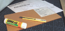
Figure D: Getting ready to glue the patterns onto an acrylic sheet
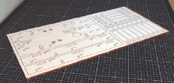
Figure E: The acrylic sheet with pattern glued and ready to cut/drill

Figure F: The pieces as they arrived from Ponoko. Burn marks are on protective sheet, not parts themselves
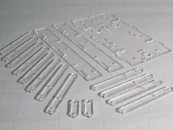
Figure G: The laser cut pieces once the protective film has been removed
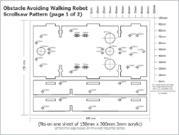
Figure H: Scroll saw pattern (and laser cutting pattern) available for download on project’s Instructable page
Note: While initially designing this robot, I experimented with different shapes of whiskers. The pattern I created is the one I found to work best, however it is quite interesting to experiment with different shapes. I was surprised how even small changes can drastically alter the navigational behavior of the robot.
4. Assembling
I tried to make assembling all the pieces together as straight-forward as possible. To this end, I’ve included a Lego-style assembly guide (51-(OAWR)-Assembly Guide.pdf).
A step before you begin:
Assemble the Tamiya twin motor gearbox (I used the 58:1 ratio with the output shaft exiting at hole “A,” however battery life on this setting is not great. Mounting holes have been included to allow for using the 203:1 ratio with the output shaft exiting at hole “C”. If you prefer a slower, longer battery life version.)
A step after you finish:
Add shoes to the feet of your robot (the rounded acrylic feet don’t grip surfaces very well). I applied a bead of hot glue to the bottom edge of each leg and performance was greatly enhanced. (But if you have access to six miniature-sized running shoes, by all means, use them.)
5. Wiring
With the big pieces all fit together and our bot starting to look pretty nice, it’s time to add the copper veins that will give it life. A first look at the wiring diagram (61-(OAWR)-Wiring Diagram.pdf) can be intimidating, but if you tackle each wire individually, it’s really quite straight forward.

Figure I: Bending the whisker. Whisker Bending Guide available on website.
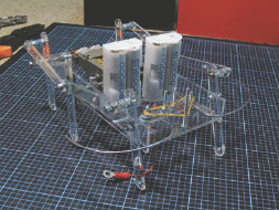
Figure J: All the parts assembled and ready for wiring.
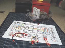
Figure K: Using the printable Wiring Diagram to easily wire up the walker

Figure L: Head-on shot of the finished walker
Four tips to (hopefully) help you out:
![]() Each wire-end that connects to a connection point should have a crimp wire terminal (red 4mm ring) affixed to it (there are 18 of these points).
Each wire-end that connects to a connection point should have a crimp wire terminal (red 4mm ring) affixed to it (there are 18 of these points).
![]() The exploded view linked to each connection point illustrates whether the wire is meant to attach above or below the acrylic sheet.
The exploded view linked to each connection point illustrates whether the wire is meant to attach above or below the acrylic sheet.
![]() Any connection point that does not already have a bolt in it uses a 3mm x 15mm bolt and a matching 3mm nut.
Any connection point that does not already have a bolt in it uses a 3mm x 15mm bolt and a matching 3mm nut.
![]() Most of all, don’t worry. The next step is fully devoted to troubleshooting so have a go and if it’s not working properly chances are you’ll find your answer there.
Most of all, don’t worry. The next step is fully devoted to troubleshooting so have a go and if it’s not working properly chances are you’ll find your answer there.
6. Troubleshooting
If you’ve made it this far and your robot is walking and avoiding obstacles, then you may skip right over this step. However, if it isn’t quite working, or is not working at all, check out the Troubleshooting section on this Instructable’s webpage and also check the Comments section where other builders share their questions and show off their successful builds.
7. Finished
Congrats! I hope you’ve reached this point without too much frustration and that you are happy with the results. If you have any tips or suggestions on how the design or Instructable could be improved, I’d love to hear them. Also, if you have finished, it would be lovely if you could post a photo to the Comments section or perhaps send me one so it can be added to this stage.
Clement Fletcher says he’s “having a lovely time being the best Clement he can be.”