
If your business card is looking too 20th century, how about one with a graphical display on it? By Tom Ward
If my flashlight business card wasn’t advanced enough for you (see “Flashlight Business Card,” page 290), how about one with a full graphical display that can be customized with any number of scrolling messages? This card could be made in quantity for about a $5 parts cost, and is only a little bit more expensive if you’re only making a few. I won’t kid you, this is not an easy design to make—don’t try it unless you have good soldering skills and some experience in electronics. Some of the components are smaller than grains of rice, so it would be useful to have good eyesight as well! Like the flashlight card, it is more of a proof of concept than something you can churn out in quantity, but it might at least give you an idea of what can be achieved, and where business cards might be in just a few years time.
1. About the design
This is the sort of card that would suit any high-tech business, or those involved in high-value contracts, where an innovative image is all-important. I would never suggest that it replace a conventional business card, but to impress that all-important prospective client, there would be more than a few companies who’d be happy to spend just a few extra dollars. Like the flashlight card, the aim here is to design a card that people just can’t throw away!
The design is really quite simple for what it does. It uses a matrix of 5 x 15 LEDs, connected to a single-chip PIC microcontroller. A handful of resistors and switches complete the design (a PDF schematic is available on the project page found via the web address at the bottom of this article). By keeping the microcontroller in sleep mode unless the buttons are pressed, the battery can last several years, and still have enough juice for a couple of thousand displays of your messages.

Figure A: The dot matrix display business card in operation
2. Materials
You will need:
![]() A CR2032 battery (I got them for about 16 cents on eBay when I bought 100)
A CR2032 battery (I got them for about 16 cents on eBay when I bought 100)
![]() A CR2032 battery holder (I used part 18-3780 from www.rapidonline.com. This costs around 14 cents in quantities of 100—these are a common type of holder that you should be able to find at places like www.mouser.com if you are on the other side of the Atlantic than I!)
A CR2032 battery holder (I used part 18-3780 from www.rapidonline.com. This costs around 14 cents in quantities of 100—these are a common type of holder that you should be able to find at places like www.mouser.com if you are on the other side of the Atlantic than I!)
![]() A PIC16F57 (Order code 1556188 from www.farnell.com—these cost 66 cents each in 100+quantities. Again, you can find them at www.mouser.com).
A PIC16F57 (Order code 1556188 from www.farnell.com—these cost 66 cents each in 100+quantities. Again, you can find them at www.mouser.com).
![]() Surface mount switches (4) (Part 78-1130 from www.rapidonline.com at 20 cents each)
Surface mount switches (4) (Part 78-1130 from www.rapidonline.com at 20 cents each)
![]() Some miscellaneous resistors and capacitors in “0805” surface-mount packages—you will need 5x100Ω resistors, 2 x 10kΩ resistors, 1 x 47kΩ resistor, 1 x 47pF capacitor, and 1 x 100nF capacitor. Any of the suppliers mentioned above do these, and they cost almost nothing!
Some miscellaneous resistors and capacitors in “0805” surface-mount packages—you will need 5x100Ω resistors, 2 x 10kΩ resistors, 1 x 47kΩ resistor, 1 x 47pF capacitor, and 1 x 100nF capacitor. Any of the suppliers mentioned above do these, and they cost almost nothing!
![]() “0603” LEDs (75)—as bright as possible, and as cheap as possible! I used item 72-8742 at 6 cents each from Rapid, but again, you should be able to get them at other suppliers. In quantity, you can get these down to about 3 cents each.
“0603” LEDs (75)—as bright as possible, and as cheap as possible! I used item 72-8742 at 6 cents each from Rapid, but again, you should be able to get them at other suppliers. In quantity, you can get these down to about 3 cents each.
![]() Some double-sided foam adhesive tape that is slightly thicker than the battery you are using—mine was 4.5mm thick
Some double-sided foam adhesive tape that is slightly thicker than the battery you are using—mine was 4.5mm thick
![]() A printed circuit board (PCB) for the project—instructions for producing your own are beyond the scope of this article, but you may have some success with the iron-on or photographic technique (my preferred technique). You can find instructions for making your own printed circuit boards elsewhere on Instructables and other sites. The PCB layout for the card can be found in a PDF file on this project’s Instructable page.
A printed circuit board (PCB) for the project—instructions for producing your own are beyond the scope of this article, but you may have some success with the iron-on or photographic technique (my preferred technique). You can find instructions for making your own printed circuit boards elsewhere on Instructables and other sites. The PCB layout for the card can be found in a PDF file on this project’s Instructable page.
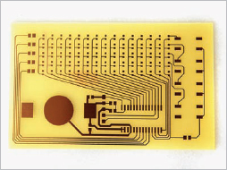
Figure B: The printed circuit before components are added

Figure C: First round of soldering complete. Whew.
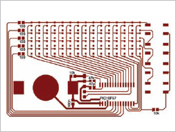
Figure D: The layout with component labels

Figure E: Our LEDs connected to the 100Ω surfacemount resistors with fine copper wire
Tools: You will also need a soldering iron (plus solder), a cutting knife, some spray adhesive, and a way of printing the front of your card—you can use a color laser or inkjet printer. I printed on OHP transparency film. You will also need a way of programming the PIC microcontroller. I use the PICKit2 which is part number 579-PG164120 from www.mouser.com, and available at around $35. A strip of 5 x 0.1" PCB pins (such as 22-0510 from Rapid) can be pushed into the programmer to act as an interface with the board.
3. Soldering starts!
Solder the components onto the board, starting with the smallest first (see Figure C). A pair of tweezers is useful here. By putting a blob of solder on a pad, and then re-melting it while positioning the resistors or capacitors with the tweezers, you can neatly add these smaller components. It doesn’t matter which way around these components go, but it does for the PIC (which should read with the writing the correct way up as shown in these photos), and also the LEDs must be put in the correct way. It is harder to tell with the LEDs which way around they should go—the top connection should be the positive (or “anode”). You can tell by consulting the datasheet for the LED—one of the two leads will usually be marked in some way. An easier way is sometimes to test one of them by attaching a couple of wires to a 1.5V battery, and then touching the leads on the ends of the LEDs. If it is the right way around, you should see a glow. If you’re using a single 1.5V battery, it will be extremely faint, so you’ll have to observe carefully. Again, a tutorial on soldering is not within the scope of this article. Note that the LEDs are only initially soldered on their bottom lead (see Figure C). We will use some wires later to connect their top leads.
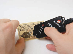
Figure F: Programming the card with the PICkit 2 programmer

Figure G: Applying double-sided foam tape
4. An ad-hoc double-sided board
Lay some fine strips of “invisible tape” down along the vertical PCB traces next to each column of LEDs. This will stop the wires we are about to solder from touching them. Next, solder some fine tinned copper wire along the top of each row of LEDs, to reach all the way to the resistor as in Figure E. Note that you will need only four wires. The top one will not be needed if you use the PCB layout found on the project page, as it uses a PCB trace to connect the components.
5. Programming
The next step is to put the display program into the chip. If you have bought the PICkit 2 programmer, it has everything you need. Download the Matrix-Code.zip file from this article’s Instructables page, unzip it, and put it in a directory somewhere on your computer. Then from within the MPLAB IDE, go to the Project menu, select Open, and navigate to the “main.asm” file. Change the stored messages (around line 115 in the code) to your contact details rather than mine(!). The messages are spelled out with a series of “1”s and “0”s—a “1” means the LED is on. If you look closely, you will see my name spelled out with “1”s. (You might need to turn your head 90 degrees to see this!) You have complete freedom to make your own characters or symbols, so you could have, for example, a simple animation of a car moving to the left if you wanted. Note that there are four messages—one for each button—you will need to specify the length of each message by stating the number of columns it takes up in the “MSG1LEN, MSG2LEN…” definitions.
Go to the Project menu again, and select Quickbuild—check that there are no errors, and you are now ready to program. I use a simple technique of inserting a broken-off strip of five pins from a strip of 0.1" header pins into the programmer, and then just touching the five pins while programming. This is a little fiddly, but as the erase or program cycle only takes a second or so, it is quite manageable. The arrow on the end pin of the programmer should align with the top pin of the PCB (NOT as shown in Figure F—Whoops!) If you are experimenting, it is well worth soldering the strip of five pins onto the board until you have finished your changes. When you are ready to program, you will have to use the separate PICkit 2 utility supplied with the programmer, as for some reason, the MPLAB IDE doesn’t support programming of the PIC16F57 directly. To do this, you need to specify the family of PICs (“baseline”), and the particular part (16F57), before loading the Hex file created in the previous step, and then finally, programming the chip. If all is successful, you should be able to insert the battery (positive side down), and press one of the buttons to see your message scroll along!
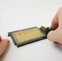
Figure H: Cutting the excess from the tape
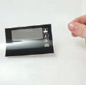
Figure I: The transparency sheet (with white icons)
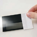
Figure J: White icons created by using a printing label on the back of the transparency
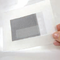
Figure K: Attaching a sheet of polypropylene to the overlay
6. Finishing off
To encapsulate the prototype card, I applied some double-sided foam tape to the board, turned it upside down, and then cut the excess off. I then reverse-printed the graphic overlay on an OHP transparency sheet. By turning the sheet over, and attaching a white printer label, you can get the clear icons on the transparency to show up white. I also attached a sheet of thick polypropylene (made as a cover for binding documents) to the overlay using some adhesive spray before attaching it to the front of the card and trimming off the excess. If you wanted to use the same graphic as mine, it is also available on this article’s page as a PDF.

Figure L: The finished design
7. The finished product
You can now relax, content that you have the world’s most advanced business card (at least until I make my next one which will have a color OLED screen!).
8. The future
If I produced these commercially, I would probably change a couple of things. First, I would change the CR2032 cell to a CR2016 as it’s thinner, and then embed it within a space cut in the PCB. By using lower-profile components, the thickness of the card could probably be reduced to about 1/8th of an inch (rather than the current 1/4"). By using some of the new thin-film batteries, it might even be possible to make a flexible card, albeit at a higher price. A professionally printed overlay and a custom die-cut replacement for the foam tape would see the cards assembled much more quickly, and look slicker too. Of course, the PCBs would be manufactured professionally as well, and populated by a “pick and place” robot to allow assembly to be sped up even further.
Next, I would like to work on a high-resolution version using a color OLED display—I’m thinking photographs and animations. The sky is the limit. Almost any electronics could be put into business cards: wireless links, audio soundtracks—if anyone is interested in using these ideas or other related ones commercially, then let me know!
Tom Ward ([email protected]) is an electrical engineer who has a short attention span and has never really grown up. He spends some of his time designing weird and wonderful gadgets, and the rest teaching science and running technology camps for children.