
Turn an ordinary umbrella into something whimsical and magical By John Kowalski

Figure A: The Electric Umbrella
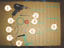
Figure B: 1. Soldering gun 2. X-Acto knife 3. Masking tape 4. Solder 5. SMD LEDs (still in their packing material) 6. Solder wick to remove excess solder 7. Mini flashlight (it’s hard to see those tiny LEDs when it’s dark!) 8. The ends of the wire—you’ll apply power here to see all the LEDs light up! 9. Solder LEDs here!
The Electric Umbrella will glow with many pinpoints of light. Carry the sun and the stars with you at night! Perfect for nighttime strolls through the countryside or just being silly. And it’s dimmeradjustable so you can set how bright you want to be—anywhere from dim ambient light for strolling in the dark to carrying your own portable supernova beacon of light!
1. What you need
The things that you need may be found through some combination of local stores, electronics parts shops, online, and scrounging parts from old electronic junk you may have lying around.
Parts and equipment:
![]() One umbrella, preferably light colored (I picked yellow), with a straight handle and a hollow shaft so that you may pass wires through it. It is very important that the umbrella be simple—none of that spring-loaded automatic stuff! You want the shaft to be hollow.
One umbrella, preferably light colored (I picked yellow), with a straight handle and a hollow shaft so that you may pass wires through it. It is very important that the umbrella be simple—none of that spring-loaded automatic stuff! You want the shaft to be hollow.
![]() 64 SMD (surface mount) LEDs in your color of choice. The actual size does not matter except that smaller will look more invisible (preferable) but will be more difficult to work with. I used size 805 (2mm wide) 3.5V white LEDs. White, blue, UV, and some greens require 3.5V and won’t require additional resistors on each LED, but 1.8V LEDs (red, yellow, green) do (more trouble!).
64 SMD (surface mount) LEDs in your color of choice. The actual size does not matter except that smaller will look more invisible (preferable) but will be more difficult to work with. I used size 805 (2mm wide) 3.5V white LEDs. White, blue, UV, and some greens require 3.5V and won’t require additional resistors on each LED, but 1.8V LEDs (red, yellow, green) do (more trouble!).
![]() A spool of thin single strand, lacquered copper wire. Thin enough to be almost invisible against the umbrella, but thick enough to withstand the occasional stresses/snags. This is what the SMD LEDs will be soldered onto.
A spool of thin single strand, lacquered copper wire. Thin enough to be almost invisible against the umbrella, but thick enough to withstand the occasional stresses/snags. This is what the SMD LEDs will be soldered onto.
![]() One 3-AA battery holder, preferably compact and arranged in an L shape, as the batteries will have to lie over the umbrella’s shaft. 3 AAA batteries would work well too, and are more compact, but won’t last as long.
One 3-AA battery holder, preferably compact and arranged in an L shape, as the batteries will have to lie over the umbrella’s shaft. 3 AAA batteries would work well too, and are more compact, but won’t last as long.
![]() Normal plastic-coated multistrand copper wire, preferably the kind that will not break easily after repeated flexing.
Normal plastic-coated multistrand copper wire, preferably the kind that will not break easily after repeated flexing.
![]() One 750Ω variable resistor with built-in on/off switch for dimming and turning the umbrella on and off.
One 750Ω variable resistor with built-in on/off switch for dimming and turning the umbrella on and off.
![]() Needle and thread (of the same color as the umbrella)
Needle and thread (of the same color as the umbrella)
![]() Solder and soldering iron/gun
Solder and soldering iron/gun
![]() Wire cutters, wire strippers, scissors, X-Acto knife
Wire cutters, wire strippers, scissors, X-Acto knife

Figure C: Each blue dot represents the placement of an LED within the umbrella
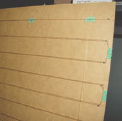
Figure D: Two fine strands of wire running back and forth across the board

Figure E: 1. This tape keeps the wires pressing against the LED 2. Surface mount LED being soldered onto the wires

Figure F: 1. LEDs before being placed onto the wire 2. Soldered LED 3. The location of an LED from the first wire/LED set
![]() Drill and drill bits
Drill and drill bits
![]() Large board and small nails, to be used for laying out the wires and soldering the SMD LEDs onto the wires.
Large board and small nails, to be used for laying out the wires and soldering the SMD LEDs onto the wires.
![]() Masking tape and double sided tape/carpet tape
Masking tape and double sided tape/carpet tape
![]() Clear epoxy or glue, Super Glue
Clear epoxy or glue, Super Glue
Figure B shows many of the parts and equipment.
2. Solder the LEDs onto the wires
Be prepared for some long and tedious steps. Carefully soldering 64 individual LEDs, each not much larger than a grain of rice, onto thin and uncooperative wires takes patience.
Before starting, measure out your umbrella and plan where each of the LEDs will go. This umbrella will have 16 spokes radiating out from the center, each spoke having 4 LEDs. I chose to have 4 different sets of LED spacing (8 of each set) to make a pseudo random looking pattern. I set the LED spacing so they’re generally closer together towards the outside of the umbrella in an effort to make the LED distribution reasonably even throughout the surface of the umbrella. Figure C shows the distribution.
Get a large board (wider than the radius of your umbrella) and hammer a bunch of nails along the sides so that you can string up/stretch out your single-strand copper wires (two wires to each nail as shown in Figure D). Place masking tape and/or mark off the points at which you will be soldering the LEDs. Leave some extra lengths of wire at each end in case you need some extra length once it comes time to actually install them onto your umbrella.
Place some masking tape under the wires to prevent burning the board (in case you ever want to use it for some other purpose) and more masking tape to hold the wires down in place as you solder. My wire was lacquer coated, so I had to first burn the coating off at the points where I planned to connect the LEDs with my soldering gun and hot solder. (You may try scraping it off instead, or using a wire stripper to strip it off.) Once the wires are tinned with solder, try to wedge an LED between the two. Be careful to place all LEDs in the same polarity!
Time to solder your first LED. I tried to apply some masking tape onto the wires so that they pinch the LED in place—makes it easier to solder the LEDs in if they’re not always moving around. With a very quick, light touch, touch both sides of the LED with the hot soldering tip, and the solder coating the wires and tip will flow into the LED contacts. If you’re not sure you got it, hook up 3V (two AA batteries) to the wires hanging off the board and see if the LED lights up! Once you get the hang of it, move on and do the rest of the LEDs. I soldered mine in two sets—half of the wire/LEDs on the board at one time (16 ‘spokes’) and the other half after finishing the first.
Check out Figures E and F for a detailed look at this.
After all the LEDs were soldered (Figure G), I applied power to the board/wires to see all the LEDs light up in their glory, as shown in Figure H. This is also a good time to determine how many volts you want your umbrella to run on, and what value variable resistor you want to use for dimming. I decided on 3 AA batteries (4.5V—3.6V if using rechargeable batteries) and a 750Ω variable resistor.
3. Assemble the central hub for the wires
All the LED spokes connect to a center hub near the tip/center of the umbrella. The tricky part is assembling this outside of the umbrella first and then carefully fitting it into the umbrella between the spokes and the cloth. I assembled it separately because it’s hard to reach the inside of an open umbrella. I also didn’t want to risk burning holes into the cloth when soldering.
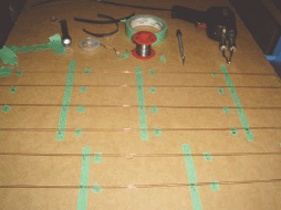
Figure G: Hard to see, but all the LEDs are soldered in place

Figure H: All 64 LEDs placed onto the board. I attached 32 at a time. The second set of 32 is placed loosely over the others.

Figure I: 1. The loops of wire are only taped together at this point; I’ve left some excess wire for later 2. The ends, cut to line up with the two wires in the hub (the tape identifies which of the four different LED sets/spacings this is and also marks the start of the length of wire) 3. First LED string attached and soldered to the hub 4. Testing the LEDs on the hub as I go along
Make two rings of wire. I used masking tape to hold its shape while putting it together. The masking tape also served to mark the spacing where each LED string was to be attached. The exact size of the rings doesn’t matter except that you want it to be fairly close to the center of the umbrella. Do not actually solder the wires into a full circle just yet as you will need these to be detached when you fit it into the umbrella later on—just hold the circle together with more masking tape for now and leave lengths of wire long enough at one end to reach the batteries once it’s inside the umbrella. Figure I shows the process.
Warning: I used the same single strand copper wire as I used for the LED strings/spokes. This was a mistake! Every time you open and close the umbrella, the wires in this hub will flex and this kind of wire will eventually break from the stresses… bad bad bad. Later on I soldered additional loops of stranded wire onto the hub. These wires are much better at holding up to stresses of repeated flexing (Figure J).
Note: The next umbrella I made used only loops of wire for the hub—see Figures K and L.
Cut the lengths of wire off the big board (4 LEDs per length). Measure the ends/length/LED placement and start soldering the strings of wire onto the hub. Make sure you get the wire/power polarity right! You can add power to the wires to see if you’re getting it right. After all 16 strings are attached, you will have an interesting glowy mess… might be used to make an interesting headpiece or hat, but we’re trying to stay focused on making an electric umbrella. :-)
4. Get the wires and hub into the umbrella
Loosely place the hub and the mess of wires near the center of the umbrella (Figure M), then carefully start sliding the hub under the umbrella’s spines so it runs around the center shaft and rests between the cloth and the spines. Carefully slide the strings of LEDs under the spines until you have two strings in each 1/8th section of the umbrella.

Figure J: 1. The dimmer is here for now—it hasn’t been added to the handle yet 2. Loops of flexible wire added to fix breakage problem in the hub 3. Loops of wire added here, too
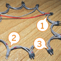
Figure K: 1. These wires go to the power source 2. Leave one connection unsoldered until the assembly is placed in the umbrella. 3. Two sets of wires all the way around, held together with heat-shrink then soldered. Red dots are positive.
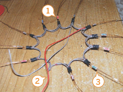
Figure L: 1. I labeled the different strings of LEDs with little bits of colored tape to make sure I didn’t mix them up 2. Do not connect a string of LEDs or solder this part together until after the assembly is placed into the umbrella 3. A string of LEDs is soldered to the hub. Little bits of heatshrink tubing cover the solder points to ensure they won’t short out.

Figure M: The battery clip is only loosely in place at this point, and the LEDs are a glowy mess before they’re carefully fitted into the umbrella

Figure N: Things are roughly in place
Once everything is roughly in place (Figure N), it’s time to attach the open ends of the hub together. Cut, strip, and twist the wire ends together. Once tied together, place some newspaper between the hub wires and the umbrella’s cloth so that you won’t burn the cloth. Solder the wires together. Once that is done, add tape to that new section on the hub so its shape and spacing matches the rest of the hub. Now you should have two wires coming off the hub. These wires will go to the battery clip/power switch/dimmer assembly.
Cut little bits of double-sided carpet tape and start placing them under the hub to keep it in place. Set it down, centered around the spokes with two strings of LEDs between each spine. Once in place, sew the hub to the spokes and cloth of the umbrella. Figure O shows the steps. Figure P shows the approach I used for another Electric Umbrella.
5. Attach the LED strings to the cloth
Things are finally starting to take shape. Now attach the LED strings to the cloth. Carefully stretch out the wires outwards towards the edges of the umbrella. I used masking tape to lie them flat on the cloth (Figure Q).
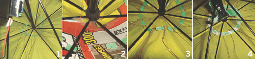
Figure O: 1. Two LED strings per section 2. Two wires going to the batteries/switch/dimmer, and the ends of the hub twisted together 3. The ends of the hub soldered and taped over 4. Sewn in place (the white stuff is doublesided tape)
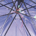
Figure P: I used a. simplified—and more durable—hub on the 2nd umbrella I put together

Figure Q: Strings of LEDs are held down with masking tape for now
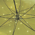
Figure R: The LEDs in place

Figure S: Hard to see, but the LEDs are being sewed on here
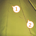
Figure T: 1. Needle and thread 2. Wires being sewn to the clo
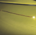
Figure U: A wire and an LED, both sewn down
Once the strings of wire are positioned, you may use a bit of Super Glue under each LED to set them on the cloth, as shown in Figure R. Make sure the wires are not twisted and that all the LEDs are facing up—or rather, facing the person holding the umbrella.
Once they’re all set in place, remove the masking tape and cut off the excess wire at the ends/edges. Try adding power to see what the umbrella will look like. It’s not finished yet, but this is the point where it finally looks like it is and you can see the lighting effect for the first time.
The Super Glue is not good enough to hold the LEDs in place forever. It’s just temporary to keep everything in place while you sew all the wires and LEDs into place. I used small stitches—one on each LED and one on the wire halfway between each LED, as shown in Figures S, T, and U.
6. Add the on/off/dimmer control
In order to add the on/off/dimmer control in the umbrella’s handle, you need to drill some holes and run wires down the umbrella’s shaft.
Drill one small hole in the shaft at the top of the umbrella—just large enough to let the fine copper wires through, but don’t insert wires yet. Next, drill out the umbrella’s handle—carefully drill a hole all the way through the handle and into the metal shaft of the umbrella. Be careful to use a drill bit just slightly smaller than the diameter inside the shaft and drill carefully right down the center of the handle until the bit pushes through. You want the hole to be large enough to let the drill shavings that went up the shaft to fall back out again. Try to get them all out.
Next you need to drill a larger hole in the handle, just deep enough for the dimmer switch to rest inside. I used a 3/4 inch bit for this, and then drilled out one side some more for the irregular shape of the dimmer switch. Again, try to get all the shavings out of the umbrella itself.
Now, it’s time to run two single strand copper wires down from the top of the umbrella and out the bottom of the handle. This part is really tricky as the wires could get bunched up inside. Pull them out again if they get stuck and try again. If the wires get too bent up, throw them away and try again with new wires.
Once you get them through the bottom of the handle successfully, solder one of the wires at the top to your battery clip, and the other to one of the wires leading to the hub/LEDs. The other wire from the hub goes directly to the second wire on the battery clip. At the bottom (the handle end), solder the wires to the switch and dimmer such that you can disconnect power altogether by turning/clicking the variable resistor all the way counterclockwise, and so that the LEDs grow brighter the more you turn it clockwise.
Once you’ve tested that it all works, glue the variable resistor in place with epoxy or other glue. If possible, find a nice decorative knob to put onto the variable resistor. Figure V shows the procedure for adding the dimmer control.
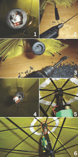
Figure V: 1. 750Ω variable resistor with on/off switch 2. Small hole going all the way through the handle The hole where the dimmer will go 4. The dimmer being fitted into the hole 5. Note the small hole for wires to go in at the top 6. Finished assembly. The batteries slide down a bit as the umbrella is folded closed.
7. Finishing up
Finally, attach the battery clip to the shaft. I left mine tied, but free to move up and down a bit—this way it can move down when you close the umbrella (further from the tip is better as it closes up pretty tight and you don’t want to add extra stresses onto the delicate wires on the LEDs), and moves up when you open it (the folding mechanism pushes the battery clip closer to the hub). And now you can take it out for a spin!
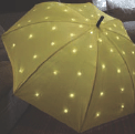
Figure W: The finished Electric Umbrella from the top

Figure X: The view from inside
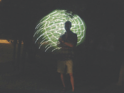
Figure Y: The Electric Umbrella in motion
It looks amazing (Figures W, X, and Y), but is a bit delicate. Don’t take it out in the wind—I don’t know if it would survive the umbrella reversing itself in the wind! Also be careful opening, closing, and transporting the umbrella so as not to put too much mechanical stress on the fine wires.
John Kowalski is a software engineer who has a passion for electronics, art, photography, and anything retro. Oh, and MacGyver is his hero.