
A crazed light-seeking robot you can make from an old computer mouse By Jacob McKenzie
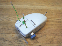
Figure A: Mousey the Junkbot, ready to terrify the cat!

Figure B: The materials list—1. Old computer mouse (for case, switch, and infrared emitters) 2. 9v battery 3. Battery snap 4. 5V relay 5. Toggle switch 6. LM386 chip 7. LED 8. 100uF capacitor 9. 2N3904/PN2222 NPN transistor 10. 1KΩ resistor 11. 10Ω resistor 12. Two small DC motors 13. Bumper plastic material 14. Cassette tape wheels 15. Rubber band for tires
Gareth Branwyn’s “Mousey the Junkbot,” from MAKE Volume 02, is a fun introduction to robotics. So fun, that I’ve created this expanded documentation of a Mousey build from start to finish, with a few extra tips and tricks you won’t find in the magazine project. This how-to is best understood after reading the original article, found on page 100 of Volume 02 (or in The Best of MAKE collection), however it is probably not required.
Mousey is a simple bot that uses two “eyes” to sense light and then turns towards the light it detects. A single large “whisker” is mounted on the front to detect collisions. A collision with a wall will cause the bot to reverse and turn, then take off in another direction. This project is pretty cheap if you have a mouse to use, the other parts can be obtained for less than ten dollars.
1. Gather the materials and tools you’ll need
Materials:
![]() An analog mouse
An analog mouse
![]() Small DC motors (2)
Small DC motors (2)
![]() A toggle switch
A toggle switch
![]() A DPDT 5v relay (Aromat DS2YE-S-DC5V works)
A DPDT 5v relay (Aromat DS2YE-S-DC5V works)
![]() An LM386 op-amp
An LM386 op-amp
![]() A 2N3904 or PN2222 NPN transistor
A 2N3904 or PN2222 NPN transistor
![]() An LED (any color)
An LED (any color)
![]() A 1KΩ resistor
A 1KΩ resistor
![]() A 10KΩ resistor
A 10KΩ resistor
![]() A 100uF Electrolytic capacitor
A 100uF Electrolytic capacitor
![]() An audio cassette tape (you know, from the ’80s)
An audio cassette tape (you know, from the ’80s)
![]() A CD-ROM or floppy disk (for the bumper)
A CD-ROM or floppy disk (for the bumper)
![]() A 9V battery snap
A 9V battery snap
![]() A 9V battery
A 9V battery
![]() Wide rubber bands (2 or 3)
Wide rubber bands (2 or 3)
![]() 22 or 24 gauge wire (some stranded, some solid core)
22 or 24 gauge wire (some stranded, some solid core)
Tools:
![]() Multimeter
Multimeter
![]() Phillips screwdriver
Phillips screwdriver
![]() Dremel
Dremel
![]() Small pliers
Small pliers
![]() Wire cutter/stripper
Wire cutter/stripper
![]() Razor knife
Razor knife
![]() Soldering iron
Soldering iron
![]() Desoldering tool of choice
Desoldering tool of choice
![]() Superglue or epoxy
Superglue or epoxy
![]() Hot glue gun and glue
Hot glue gun and glue
![]() Hacksaw
Hacksaw
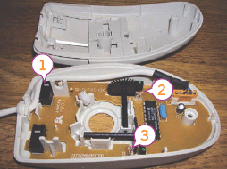
Figure C: The components scavenged from a mouse: 1. Momentary switch 2. & 3. Infrared emitters
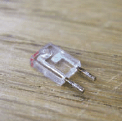
Figure D: An infrared emitter close-up

Figure E: The mouse case before the carnage begins
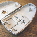
Figure F: The bottom case with everything removed except the screw post

Figure G: The notch cut for the bumper switch

Figure H: The bumper switch installed
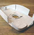
Figure I: The side notches for the motors cut
2. Scavenge some parts
Mousey requires several parts that we can conveniently borrow from a donor mouse, its eyes and its whisker.
Open up the mouse and locate the components that we’ll be harvesting, the momentary switch and the infrared emitters. The emitters are the components in the clear package (Figure C).
Remove the PCB and desolder the push switch and both infrared emitters.
3. Prepare the case
Next we need to give Mousey’s insides a cozy place to live, so break out your Dremel and remove all of the internal plastic structure from the top and bottom of the mouse. If your mouse is small, you may have to remove the screw posts that hold the mouse together. Now use the Dremel to cut openings for the bump switch in the front of the mouse and motors on the sides.
The best Dremel bit to use for this is the short cylindrical one, it will cut a good right angle if the Dremel is held vertically.
4. Make the wheels
The axles on these motors are pretty small and if we want Mousey to be stable at the blazing mouse speeds he travels, we need to make some rims. Cassette tapes have a rim that’s the perfect size in the bottom right and left corners (if the open side is down). It might take a couple tries opening different brands of tapes before you get ones that fit your axles perfectly (Figure J). Once you find some rims you're happy with, super glue them to the axles (Figure K).
Cut the rubber band and super glue it to the rim then wrap it around three times, adding super glue every half-turn or so to keep it together (Figure L). Cut off the leftover rubber.
Next, glue another rubber band back to the rubber band that you just wrapped. Complete one revolution and cut off the extra (Figure M). Don't forget to add enough glue to keep the outside rubber band on. Repeat the same process for the other wheel.

Figure J: The transport wheels from a cassette tape

Figure K: Our tape wheel hub fitted to a motor
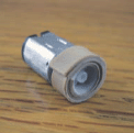
Figure L: The “inner tube” of our wheel
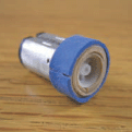
Figure M: The outer tire finishes it off. Traction, baby!
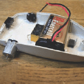
Figure N: The component layout on this mouse. Mice are different, so you’ll have to carefully think out where everything goes.
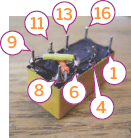
Figure O: The relay upside down with pins 8 to 11 and 6 to 9 soldered
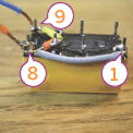
Figure P: Pins 1 and 8 connected and stranded wire soldered to pins 8 and 9
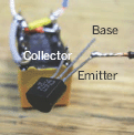
Figure Q: The transistor soldered to the relay. Note location of collector, base, and emitter pins in relation to flat side of the transistor.
5. Layout the design and install the relay
There are quite a few good component layouts for Mousey. The best layout is probably the one pictured on the top of page 100 of MAKE Volume 02. However, this alternate setup pictured in Figure N works better on certain mice. I chose to use the standard layout. The circuitry of the mouse will be free-formed since there is not much extra room for a PCB.
Note: Max Headroom! Even with the tightest wire management, this little bot has a lot of wires inside. Be mindful while you’re building it that you have to be able to fit the top onto it when you’re done. Keep your wire runs as short as humanly possible.
Once we know where everything will go, it’s time to get to the real work. Set down the relay and solder wires in an “X” connecting pins 8 to 11 and 6 to 9 (see the pin labels in Figure O).
Connect pins 1 and 8 with a wire along the side and add stranded wire to leads 8 and 9 (Figure P).
Solder the collector of the transistor (right pin looking at the flat side) to pin 16 and clip the lead short. Then connect the wire we soldered to pin 9 to the emitter (left pin looking at the flat side) leaving a little bit of slack (Figure Q).
Now glue the relay into the mouse case. I have added two clipped leads to act as positive and negative voltage rails that will get rid of some clutter in the motor area. Use your razor knife to strip the shielding from the wire connecting pin 9 and the emitter and solder it to the negative (-) voltage rail. Then connect pin 8 to the positive (+) voltage rail.
Note: In Figure R (and Figure T), ignore the blue wire. It was going to be the one connected to the transistor, but I replaced it with the black wire you see in the photo. Also note the power rails marked (+) and (-).
6. Install the bump switch
Now let’s give the Mousebot his whisker. Make it by soldering the positive lead of the capacitor and the 10kΩ resistor to the end pin on the switch that is Normally Open (NO). You can check which side is the open side of the push switch by using the Continuity Check feature of your multimeter. There should be no connection between the middle and Normally Open pin until the switch is pressed. Once this is done, add stranded wire to the ground lead (-) of the capacitor and the middle pin of the switch.

Figure R: The relay and transistor glued in place and our “power rails” installed
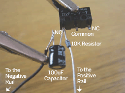
Figure S: Resistor/capacitor circuit attached to bump switch

Figure T: This mouse does not have enough room in the back so the chip should go in the front where there is more free real estate.

Figure U: The LM386 with pins 1 and 8 connected
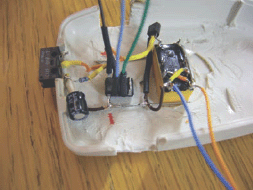
Figure V: Pin 4 of the 386 connected to the (-) rail, pin 6 to (+) and stranded wire added to pins 2, 3, 5
Connect the resistor on the switch to the base (middle pin) of the transistor and the wire from the ground side (-) of the capacitor to the (-) voltage rail. Then connect the middle pin to the (+) voltage rail. To make your joints a bit more secure, you can use heat-shrink tubing to insulate the connections and bend the capacitor to the side to free up a little more space (Figure T).
7. Build Mousey’s brain
Mousey’s brain is the LM386 op-amp chip, flip it onto its back (pins up) and bend pins 1 and 8 so that they are touching and add some solder to connect them (Figure U).
Note: There are much larger versions of all these images on the Instructables page for this project. On the webpage, just click on the [i] symbol in the upper left corner of each image to view an enlargement.
Now place the LM386 into position and connect pin 4 to the (-) rail, pin 6 to the (+) rail, and add stranded wire to pins 2, 3, and 5 (Figure V).
We are almost ready to connect the motors, so solder some stranded wire to pins 4 and 13 of the relay. At this point your mousebot should look something like the one in Figure W.
8. Construct Mousey’s top half
First drill three small holes at the front of the mouse for the two eyestalks and sensitivity-boosting LED (Figure X). Then drill a larger hole for your toggle switch at the back of the mouse and install the switch to form the bot’s on/off tail switch (Figure Y).
To create Mousey’s eyestalks, twist two pieces of solid-core wire together and solder the infrared emitter to the leads on one end (Figure Z). Place the LED in the middle hole and connect the (+) lead to the 1kΩ resistor (Figure ZA).
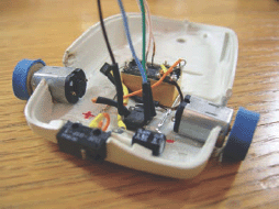
Figure W: Most of the bottom half of the bot is in place and wired up
Next use the Diode Check feature of your multimeter to find the (-) leads of the infrared emitters and connect them to the (-) lead of the LED.
9. Glue down the components
Use hot glue or epoxy to secure the bump switch and the motors to the mouse chassis. I used a combination of Super Glue and hot glue to hold in the bump switch and hot glue on the motors. Make sure the angle of the motors are roughly equal and extend down far enough to raise the front of the mouse slightly off of the ground.
10. Finish up the connections
Connect pin 13 of the relay to the left motor and pin 4 of the relay to the right motor. Now connect pin 5 of the IC (brown wire in Figure ZF) to the ground node of both motors. If you aren’t sure which side is (+) and which is (-) on your motor, connect it to a battery and observe the direction of the spin. The right motor should spin clockwise if you are looking at the wheel and the left should spin counter-clockwise.
Locate the wire coming from IC pin 2 (green) to the (+) lead of the left eyestalk and IC pin 3 (blue) to the (+) lead of the right eyestalk. Then wire the 1kΩ resistor to the (+) voltage rail.
Hook up the battery by soldering the black wire (-) on the battery cap to the negative voltage rail. Connect the red wire (+) on the battery cap to the switch and then connect the switch back to the (+) voltage rail.
Replace the cover of the mouse and cut a thin strip of your bumper material with a saw or knife. Attach the strip with epoxy or hot glue on one side so that wherever you apply pressure the button clicks. Once you have the strip attached, give yourself a pat on the back, you’re done!

Figure X: The holes drilled for the eyestalks and the LED lamp
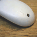
Figure Y: The hole drilled for the tail toggle switch
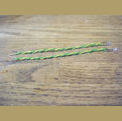
Figure Z: The two infrared eyestalks

Figure ZA: Installation of the LED sensitivity circuit
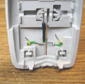
Figure ZB: The eyestalks installed and connected to the LED

Figure ZC: The top half of Mousey completed
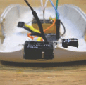
Figure ZD: The bump/whisker switch glued in place

Figure ZE: The DC motors glued in place
Flip the switch and enjoy your crazy mousebot!
Jacob McKenzie is a mechanical engineering student at UC Berkeley and former MAKE magazine intern. He thinks bicycles and Lagrangian mechanics are both awesome.
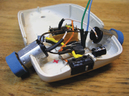
Figure ZF: Making the final wire connections—connecting the motors

Figure ZG: Connecting the eyestalks to the LM386
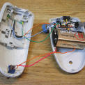
Figure ZH: Connecting the power switch to the circuit

Figure ZI: Attach the bumper and you’re ready for your mouse to roar
User Notes
Gareth Branwyn says: Builders of this project should be aware of the fact that the wiring for the LED light sensor sensitivity subcircuit, as detailed in the MAKE article, in my book Absolute Beginner’s Guide to Building Robots, AND in Dave Hrynkiw’s Junkbots book, is incorrect. You can find the corrected circuit diagram at streettech.com/robotbook/circuitMousey.html. It’s only a minor change in how the circuit is wired. The bot works fine as seen here, but the eyes will be a bit more sensitive with the corrected wiring.
There are many resources related to Mousey the Junkbot that can be found, starting with the Mousey the Junkbot FAQ (http://tinyurl.com/5pv6uw).
A complete, free PDF of the original project in MAKE Volume 02 can be downloaded here: http://cdn.makezine.com/make/mousey.pdf.
Solarbotics.com, purveyors of fine robots and robot accessories, sells a Mousey the Junkbot parts bundle. It comes with everything you need to build this project. It even includes a pair of infrared optical eyes and a SPDT switch with a lever on it (for easily attaching the bumper), parts you’d normally have to get from inside the mouse. With this bundle, all you need to provide is the mouse case itself (or anything else you’d care to house your bot in).
Mousey funfact: Mousey the Junkbot was a guest, along with MAKE Editor in Chief Mark Frauenfelder, on the Colbert Report. In the midst of the segment, Stephen Colbert turned Mousey on, it tore off of the table, onto the floor, and smashed to pieces. Colbert seemed genuinely embarrassed. You can see the segment here: http://tinyurl.com/585u2f. Mark also shows off the Marshmallow Shooter also featured in this book.