
10
Voltage Control
OBJECTIVES
After reading this chapter, you should be able to:
obtain an overview of voltage control
discuss the parameters or equipments causing reactive power
understand the methods of voltage control and
calculate the rating of synchronous phase modifier
10.1 INTRODUCTION
A power system must be designed in such a way so as to maintain the voltage variations at the consumer terminals within specified limits. In practice, all the equipments on the power system are designed to operate satisfactorily at the rated voltages or within specified limits, at most ± 6% at the consumer terminals. The main reason for the variation in voltage at the consumer terminals is the variation in load on the supply power system. In case load on the supply system increases, the voltage at the consumer terminals decreases due to an increase in voltage drop in power system components and vice versa when load is decreased. Most of the electronic equipments are sensitive to voltage variations; hence, the voltage must be maintained constant. It can be maintained within the limits by providing voltage-control equipment.
10.2 NECESSITY OF VOLTAGE CONTROL
The voltage at the consumer terminals changes with the variation in load on the supply system, which is undesirable due to the following reasons:
- In case of lighting load, for example, incandescent lamp is acutely sensitive to voltage changes. Fluctuations in voltage beyond a certain level may even decrease the life of the lamp.
- In case of power load consisting of induction motors, the voltage variations may cause a variation in the torque of an induction motor, as the torque is proportional to the square of the terminal voltage. If the supply voltage is low, then the starting torque of the motor will be too low.
- If the voltage variation is more than a specified value, then the performance of the equipments suffers and the life of the equipment is reduced.
- The picture on a television set starts rolling if the voltage is below a certain level because the fluorescent tube refuses to glow at low voltages. Hence, voltage variations must be regulated and kept to a minimum level.
Before discussing the various methods of voltage control, it is very important to know about the various sources and sinks of reactive power in a power system.
Test Yourself
Why is voltage tolerance more than frequency tolerance?
10.3 GENERATION AND ABSORPTION OF REACTIVE POWER
- Synchronous machine: These can be used either to generate or absorb reactive power. The ability to supply reactive power is determined by the short-circuit ratio
 An overexcited synchronous machine generates kVAr and acts as a shunt capacitor, while a underexcited synchronous machine absorbs it and acts as a shunt reactor. The machine is the main source of supply to the system of both positive and negative VArs.
 - Overhead lines: When fully loaded, lines absorb reactive power with a current I amperes for a line of reactance per phase X ohms, the VArs absorbed are I 2X per phase. On light loads, the shunt capacitances of longer lines may become predominant and the lines then become VAr generators.
- Transformers: Transformers absorb reactive power. The mathematical expression for the reactive power absorbed by a transformer is QT = 3 ∣I ∣2 XT VAr. where XT is the transformer reactance per phase in ohms and ∣I ∣ is the current flowing through in amperes.
- Cables: Cables act as VAr generators because they have a very small inductance and relatively very large capacitance due to the nearness of the conductors.
- Loads: A load at 0.8 p.f. implies a reactive power demand of 0.75 kVAr per kW of power, which is more significant than the simple quoting of the p.f. In planning power systems, it is required to consider reactive power requirements to ascertain whether the generator is able to operate any range of p.f.
10.4 LOCATION OF VOLTAGE-CONTROL EQUIPMENT
The consumer apparatus should operate satisfactorily. This is achieved by installing voltage-control equipment at suitable places.
The voltage-control equipment is placed in two or more than two places in a power system because of the following reasons:
- The power system is a combination of wide-ranging networks and there is a voltage drop in different sections of the distribution and transmission systems.
- The various circuits of a power system have different load characteristics.
The voltage-control equipment is placed at:
- Generating stations.
- Transformer stations.
- The feeders.
When power is supplied to a load through a transmission line keeping the sending-end voltage constant, the receiving-end voltage varies with magnitude of load and p.f. of the load. The higher the load with smaller p.f., the greater is the voltage variation.
10.5 METHODS OF VOLTAGE CONTROL
The different voltage-control methods are:
- Excitation control.
- Shunt capacitors.
- Series capacitors.
- Tap-changing transformers.
- Boosters.
- Synchronous condensers.
10.5.1 Excitation control
This method is used only at the generating station. Due to the voltage drop in the synchronous reactance of armature, the alternator terminal voltage changes and hence the load on the supply system also undergoes a change. This can be maintained constant by changing the field current of the alternator. This process is called excitation control. By using an automatic or a hand-operated regulator, the excitation of the alternator can be controlled.
In modern systems, automatic regulator is preferred. The two main types of automatic voltage regulators are:
- Tirril regulator.
- Brown-Boveri regulator
(a) Tirril automatic regulator: Tirril regulator is a fast-acting electromagnetical regulator and it gives ± 0.5% regulating deviation between no-load and full load of an alternator.
Construction: Tirril voltage regulator is a vibrating-type voltage regulator in which a resistance R is connected in the exciter circuit to get the required value of voltage by adjusting the proper value of resistance. Figure 10.1 shows the main parts of the Tirril voltage regulator.
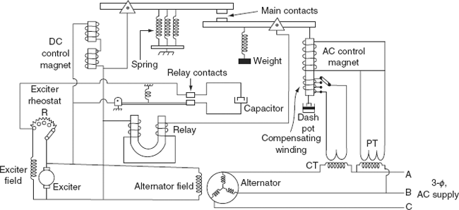
FIG. 10.1 Tirril automatic voltage regulator
Differential relay: It is a ‘U’-shaped (horseshoe) relay magnet. It has two identical windings on both limbs as shown in Fig. 10.1, which are connected across the armature of the exciter only when the main contacts are closed. A capacitor is connected in parallel to the relay for reducing the spark when the relay contacts are opened.
Excitation system: It consists of a solenoid energized by the voltage equal to the exciter terminal voltage. The counter-balance force of an excitation solenoid is provided by three springs, which are acting in sequence and are shown in Fig. 10.1.
Main control unit: It is a solenoid excited from an AC supply. The lower part of this solenoid is connected with a dashpot, which provides damping to the measuring unit.
Main contacts: These are attached to the levers that are operated by measuring and excitation solenoids as shown in Fig. 10.1. The lever on the left side is controlled by the exciter control magnet and the lever on the right side is controlled by the main control magnet.
Principle of operation: Under normal operating conditions, i.e., the system is operating at pre-set load and voltage conditions, the main contacts are open. The field rheostat is in the circuit. If the load on the alternator increases, the terminal voltage decreases. When the pre-set excitation settings of the device is low, the m.m.f developed by the measuring system or the solenoid is low, causing a disturbance in the equilibrium and, therefore, main contacts are closed. These results in de-energization of differential relay and relay contacts are closed. So, the resistance ‘R’ in the field is short-circuited. When this is out of circuit, total field current flows through the exciter, and the exciter terminal voltage increases. Thus, the voltage across the alternator terminals increases due to the increase in alternator field current.
Due to this increased voltage, the pull of the solenoid exceeds the spring force and so the main contacts are opened again and the resistance is inserted in the exciter field. A similar process is repeated if the terminal voltage is reduced.
(b) Brown-Boveri regulator: This differs from the Tirril regulator. In this, the resistance of regulator is either gradually varied or varied in small steps.
Construction: Brown-Boveri regulator is not a vibrating type; hence, wear and tear is less when compared to that of a tirril regulator. It consists of four main parts and its schematic diagram is shown in Fig. 10.2(a).
Control system: It contains two windings ‘P’ and ‘Q’ wound on an annular core of laminated steel sheet as shown in Fig. 10.2(a). The windings are excited from the three-phase alternator supply through the resistances Rc and Rf and resistance Rse is inserted in winding ‘P’. The ratio of resistance to reactance is adjusted in such a way so as to get a phase angle difference between the currents in two windings. This results in the formation of a rotating magnetic field and hence develops an electromagnetic torque on the aluminium drum D. This torque depends on the terminal voltage of the alternator and on the resistances Rc and Rf. The torque decreases with increased values of Rf.
Operating system: It consists of two resistance sectors made up of contact blocks on the inner surface of roll-contact segments as shown in Fig. 10.2(b). Contact segments and resistance sectors are made to contact by using springs. The two resistance sectors R and R are connected in series, and this combination is connected in series with exciter field circuits. If the alternator voltage changes from its pre-determined value, the contact segments roll on the inside of resistance sectors, rotates clock-wise or anti-clock-wise under the action of the two windings P and Q.

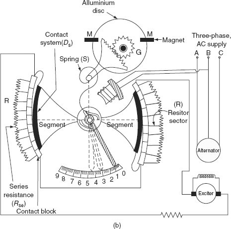
FIG. 10.2 (a) Schematic diagram of Brown-Boveri regulator; (b) detailed diagram of Brown-Boveri regulator
Mechanical control torque: Mechanical torque is produced by springs (main and auxiliary) and is independent of the position of the control system. In a steady deflection state, the mechanical torque is equal to the electrical torque, which is produced by the current in the split-phase winding.
Damping torque: It consists of an aluminium disc, which is rotated in between two magnets M and M, and a spring S is attached to it. When there is a change in the alternator voltage, eddy currents are produced in the disc and torque is developed; thereby controlling the response of the moving system.
Principle of operation: Suppose the voltage of the alternator terminals is set to the normal value by adjusting Rc and Rf and is in Position-3 on the scale. In this position, the mechanical torque is equal to the electromagnetic torque and the moving system is under equilibrium.
Let us assume that the terminal voltage of the alternator is reduced due to the rise in load, and then the electromagnetic torque is reduced. At this instant, the mechanical torque is greater than the electromagnetic torque and the disc starts to rotate (assume in anti-clock-wise direction). Due to this, the pointer moves to Position-1. The resistance in the exciter field will be reduced, which causes an increase in the exciter field current. So, the terminal voltage of an alternator increases.
10.5.2 Shunt capacitors and reactors
Shunt capacitors are used for lagging p.f. circuits; whereas reactors are used for leading p.f. circuits such as those created by lightly loaded cables. In both cases, the effect is to supply the required reactive power to maintain the values of the voltage. Apart from synchronous machines, static shunt capacitors offer the cheapest means of reactive power supply but these are not as flexible as synchronous condensers.
Capacitors are connected to a bus bar or to the tertiary winding of a main transformer. In this method, as the voltage falls, the VArs produced by a shunt capacitor or reactor also falls. Thus, their effectiveness falls when needed. Also for light loads, when the voltage is high, the capacitor output is large and the voltage tends to become excessive. the view of a three-phase capacitor bank on a 11-kV distribution line is shown in Fig. 10.3.
11.5.3 Series capacitors
Capacitors are installed in series with transmission lines (shown in Fig. 10.4) in order to reduce voltage drop. The series capacitors compensate the reactance voltage drop in the line by reducing net reactance. A capacitor in series with a transmission line serving a lagging p.f. load will cause a rise in voltage as the load increases. The p.f. of the load through the series capacitor and line must be lagging if the voltage drop is to decrease appreciably. The voltage on the load side of the series capacitor is raised above the source side, acting to improve the voltage regulation of the feeder. Since the voltage rise or drop occurs instantaneously with variations in the load, the series capacitor response as a voltage regulator is faster and smoother than the regulators.
The main drawback of this capacitor is the high voltage produced across the capacitor terminals under short-circuit conditions. The drop across the capacitor is If Xc, where If is the fault current which is many times the full-load current under certain circuit conditions. It is essential, therefore, that the capacitor is taken out of service as quickly as possible. A spark gap with a high-speed contactor can be used to protect the capacitor under these conditions.
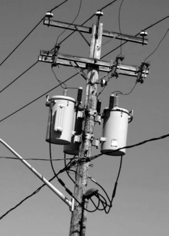
FIG. 10.3 View of a three-phase capacitor bank on a 11-kV distribution line
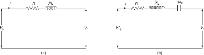
FIG. 10.4 Circuit diagram without and with series compensation
Figures 10.4 and 10.5 show the line and its voltage phasor diagrams without and with series compensation. The voltage drop of the line without a series capacitor is approximately given by
Vd = Ir R cos ϕ + Ir XL sin ϕ
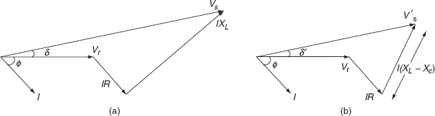
FIG. 10.5 Phasor diagrams of Fig. 10.4
and the voltage drop with a series capacitor,
Vd = Ir R cos ϕ + Ir (XL − XC) sin ϕ
where Xc is the capacitive reactance of the series capacitor. A comparison between shunt and series capacitors is tabulated below (Table 10.1).
10.5.4 Tap-changing transformers
A tap-changing transformer is a static device having a number of tap settings on its secondary side for obtaining different secondary voltages. The basic function of this device is to change the transformation ratio, whereby the voltage in the secondary circuit is varied making possible voltage control at all voltage levels at any load. The supply may not be interrupted when tap changing is done with and without load.
Types of tap-changing transformers are:
- Off-load tap-changing transformer.
- On-load tap-changing transformer.
TABLE 10.1 Comparison of shunt and series capacitors
| Shunt capacitor | Series capacitor |
|---|---|
1. Supplies fixed amount of reactive power to the system at the point where they are installed. Its effect is felt in the circuit from the location towards supply source only |
1. Quantum of compensation is independent of load current and instantaneous changes occur. Its effect is from its location towards the load end |
2. It reduces the reactive power fl owing in the line and causes:
|
2. It is effective:
|
3. The location has to be as near to the load point as possible. In practice, due to the high compensation required, it is found to be economical to provide group compensation on lines and sub-stations |
3. As a thumb rule, the best location is 1/3rd of electrical impedance from the source bus |
4. As fixed kVAr is supplied, this may sometimes result in overcompensation in the light-load period. Switched kVAr banks are comparatively costlier than fixed kVAr and become necessary |
4. As full-load current is to pass through, the capacity (current rating) should be more than the load current |
5. As the p.f. approaches unity, larger compensation is required for the improvement of p.f. |
5. As series capacitors carry fault current, special protection is required to protect from fault current |
6. Where lines are heavily loaded, compensation required will be more |
6. Causes sudden rises in voltage at the location |
7. Cost of compensation is lower than that of the cost required for series capacitor |
7. Cost of a series capacitor is higher than that of a shunt capacitor |
10.5.4.1 Off-load tap-changing transformers
The simple tap-changing arrangement of a transformer is shown in Fig. 10.6. The voltage can be varied by varying a number of tappings on the secondary side of the transformer as shown in Fig. 10.6.
Figure 10.6 refers to the off-load tap-changing transformer, which requires the disconnection of the transformer from the load when the tap setting is to be changed.
The output of the secondary side of the transformer changes with the change in the tap position of the secondary winding. The secondary voltage is minimum when the movable arm makes contact with stud 1, whereas it is maximum when it is in position N. When the load on the transformer increases, the voltage across secondary terminals decreases. This can be increased to the desired value by adding the number of turns on the secondary of the transformer by changing taps.

FIG. 10.6 Off-load tap-changing transformer arrangement
Thus, in the case of tap-changing transformers, the main drawback is that the taps are changed only after the removal of the load. This can be overcome by using an on-load tap-changing transformer with reactors.
10.5.4.2 On-load tap-changing transformer
To supply uninterrupted power to the load (consumer), tap changing has to be performed when the system is on load. The secondary winding in a tap-changing transformer consists of two identical parallel windings with similar tappings. For example, 1, 2, …, N and 1′, 2′, …, N′ are the tappings on both the parallel windings of such a transformer. These two parallel windings are controlled by switches Sa and Sb as shown in Fig. 10.7(a). In the normal operating conditions, switches Sa, Sb, and tappings 1 and 1′ are closed, i.e., both the secondary windings of the transformer are connected in parallel, and each winding carries half of the total load current by an equal sharing. The secondary side of the transformer is at a rated voltage under no load, when the switches Sa and Sb are closed and movable arms make contact with stud 1 and 1′, whereas it is maximum (above the rated value) under no load, when the movable arms are in position N and N′. The voltage at the secondary terminal decreases with an increase in the load. To compensate for the decreased voltages, it is required to change switches from positions 1 and 1′ to positions 2 and 2′ (number of turns on the secondary is increased). For this, open any one of the switches Sa and Sb, assuming that Sa is opened. At this instant, the secondary winding controlled by switch Sb carries full-load current through one winding. Then, the tapping is changed to position 2 on the winding of the disconnected transformer and close the switch Sa. After this, switch Sb is opened for disconnecting its winding, and change the tapping position from 1′ to 2′ and then switch Sb is closed. Similarly, tapping positions can be changed without interrupting the power supply to the consumers. The online tap-changing transformer is shown in Fig. 10.7(b).
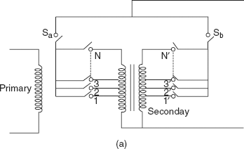
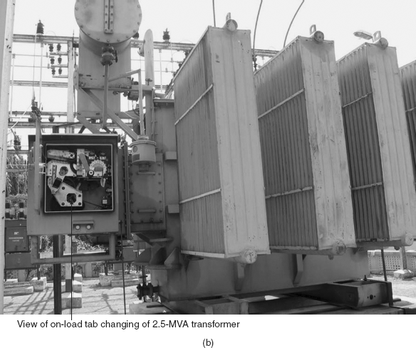
FIG. 10.7 (a) On-load tap-changing transformer arrangement; (b) on-line tap-changing transfomer
This method has the following disadvantages:
- It requires two windings with rated current-carrying capacity instead of one winding.
- It requires two operations for the change of a single step.
- Complications are introduced in the design in order to obtain a high reactance between the parallel windings.
10.5.5 Booster transformers
The booster transformer performs the function of boosting the voltage. It can be installed at a sub-station or at any intermediate point of line.
In the circuit shown in Fig. 10.8(a), P and Q are the two relays. The secondary of the booster transformer is connected in series with the line whose voltage is to be controlled, and the primary of the booster transformer is supplied from a regulating transformer with on-load tap-changing gear. The booster can be brought into the circuit by the closure of relay Q and the opening of relay P, and vice versa as shown in Fig. 10.8(a). The secondary of the booster transformer injects a voltage in phase with the line voltages. By changing the tapping on the regulating transformer, the magnitude of VQ can be changed and thus the feeder voltage VF can be regulated. The view of booster and distribution transformer connection (left to right) is shown in Fig. 10.8(b).
Advantages
- It can be installed at any intermediate point in the system.
- The rating of the booster transformer is about 10% that of the main transformer (product of current and injected voltage).
Disadvantages
When used in conjunction with main transformer:
- More expensive than a transformer with on-load tap changes.
- Less efficient due to losses in booster.
- Requires more space.
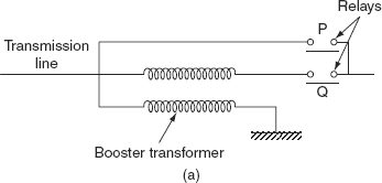

FIG. 10.8 (a) Booster transformer; (b) view of booster and distribution transfomer connection (left to right)
10.5.6 Synchronous condensers
A synchronous condenser (synchronous phase modifier) is a synchronous motor running without mechanical load. It is connected in parallel with the load at the receiving end of the line. Depending upon its excitation, it either generates or absorbs the reactive power. It takes leading current when its field is overexcited, i.e., above normal speed and takes lagging current when it is underexcited. Thus, the current drawn by a synchronous phase modifier can be varied from lagging to leading by varying its excitation. It is a very convenient device to keep the receiving-end voltage constant under any condition of load. It also improves the p.f. and the output can vary smoothly.
TABLE 10.2 Comparison of synchronous condenser and static capacitors
| Synchronous condenser | Static capacitors |
|---|---|
1. Harmonics in the voltage does not exist |
1. Large harmonics are produced in the system |
2. Power factor variation is stepless (uniform) |
2. Power factor varies in steps |
3. It allows overloading for a short period |
3. It does not allow any overloading |
4. Power loss is more |
4. Power loss is less |
5. It is more economical in the case of large kVAr |
5. It is more economical for small kVAr requirement |
6. Failure rate is less and, therefore, this is more reliable |
6. Failure rate is more and, therefore, it is less reliable |
A synchronous phase modifier has a smaller shaft and bearing and higher speed as compared to a synchronous motor used for mechanical loads. A synchronous phase modifier has higher overall efficiency as compared with a synchronous motor.
Advantages
- Flexibility for use in all load conditions because when the machine is under excited, it consumes reactive power.
- There is a smooth variation of reactive VArs by synchronous capacitors.
- It can be overloaded for short periods.
Disadvantages
- Possibility of falling out of control in case of sudden changes in voltage.
- These machines add to short-circuit capacity of the system during fault condition.
A comparison between synchronous condenser and static capacitors is presented in Table 10.2.
10.6 RATING OF SYNCHRONOUS PHASE MODIFIER
An expression of sending-end voltage in terms of transmission line constants is
where
|
= |
Vs ∠δ = sending-end voltage |
|
= |
receiving-end voltage (reference phasor) |
Īr |
= |
Ir∠ − φr = receiving-end current |
Ā |
= |
A∠α |
|
= |
B∠β are the line constants |
Equation (10.1) can be written in a phasor form as
Vs ∠δ |
= |
AVr∠α + BIr ∠ (β − φr) |
|
|
= |
AVr cos α + jAVr sin α + BIr cos (β − φr) + jBIr sin(β − φr) |
(10.2) |
The real part of Equation (10.2) is
Vs cos δ = AVr cos α + BIr cos (β − φr) (10.3)
and the imaginary part is
Vs sinδ = AVr sin α + BIr sin (β − φr) (10.4)
Squaring and adding Equations (10.3) and (10.4), we get
V2s |
= |
A2V2r + B2I2r + 2ABrIr cos α cos (β − φr) + 2ABVrIr sin α sin(β − φr) |
|
|
= |
A2V2r + B2I2r + 2ABVrIr cos(α − β + φr) |
|
|
= |
A2V2r + B2I2r + 2ABVrIr [cos(α − β) cos φr − sin(α − β) sin φr] |
(10.5) |
Real power at receiving end, Pr = Vr Ir cosϕr
Reactive power at receiving end, Qr = Vr Ir sinϕr
Receiving-end current can be written as
Ir = Ir cos φr − jIr sin φr (∵ lagging p.f.)
= Ip − jIq
∴ I2r = I2p + I2q
where ![]()
Substituting the above quantities in Equation (10.5), we have
V2s = A2V2r + B2I2r + 2ABPr cos(α − β) − 2AB Qr sin(α − β) (10.6)
In Equation (10.6), Ir2 is replaced by Ip2 and Iq2 expressions,
Equation (10.7) is useful for calculating the sending-end voltage by knowing the values of A, B, α, β, Pr, Qr, and Vr (or) sometimes the sending-end and receiving-end voltages are fixed and A, B, α, β, Pr, and Qr are given. It is required to find out the rating of the phase modifier. In this case, the required quantity is Qr, where Qr is the net reactive power at the receiving end and not the reactive power for the load. So, if the net reactive power required to maintain certain voltages at the two ends is known, the rating of the phase modifier can be found.
Example 10.1: A 3-ϕ overhead line has resistance and reactance per phase of 25 and 90 Ω, respectively. The supply voltage is 145 kV while the load-end voltage is maintained at 132 kV for all loads by an automatically controlled synchronous phase modifier. If the kVAr rating of the modifier has the same value for zero loads as for a load of 50 MW, find the rating of the synchronous phase modifier.
Solution:
We have Vs = AVr + BIr (10.9)
From given data:
Sending-end voltage, ![]()
Receiving-end voltage, ![]()
Line impedance, Z = 25 + j90
Assuming short-line model, Vs = Vr + IrZ

Comparing Equations (10.9) and (10.10), we have
A = 1; α = 0,
B = 93.4 β = 74.47°
Pr = Vr Ir cos ϕr = 50 MW (given)
Substituting these values in Equation (10.8), we get
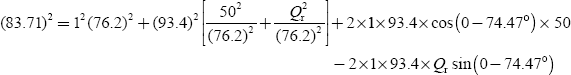
1, 200.92 × 106 = 3,755.98 × 106 + 1.50Q2r × 106 + 2,500.7 × 106 + 179.98Qr
1, 200.92 = 3,755.98 + 1.50Q2r + 2,500.7 + 179.98Qr
1.50Q2r + 179.98Qr + 5,055.76 = 0
Solving the above equation, we get
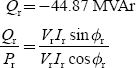
Power factor angle at the receiving-end voltage, ϕr = −41.9°
∴ The power factor is cosϕr = 0.7442 leading
∴ The rating of the synchronous modifier = 44.87 MVArs
Example 10.2: A 3-ϕ feeder having a resistance of 3 Ω and a reactance of 10 Ω supplies a load of 2 MW at 0.85 p.f. lag. The receiving-end voltage is maintained at 11 kV by means of a static condenser drawing 2.1 MVAr from the line (Fig. 10.9). Calculate the sending-end voltage and p.f. What is the regulation and efficiency of the feeder?
Solution:
Load current,

Shunt branch current,

Receiving-end current, |
Ir |
= |
IL + IC |
|
|
= |
123.5∠ − 31.79° + 110.22∠90° |
|
|
= |
105 − j65 + j110.22 |
|
|
= |
105 + j45.22 |
|
|
= |
114.3∠23.3° A |
The vector diagram is shown in Fig. 10.10. Here, the current is a leading current.
From the circuit diagram shown in Fig. 10.9,
The sending-end voltage, Vs = Vr + IrZ

FIG. 10.9 Circuit diagram
FIG. 10.10 Phasor diagram
= 6,350.85∠0 + 1,193.33∠96.6
= 6,350.85 + j0 − 137.16 + j1,185.42
= 6,213.69 + j1,185.42
= 6,325.74∠10.8 V
∴ The sending-end voltage,
From the phasor diagram shown in Fig. 10.10,
sending-end p.f. = cos (23.3 — 10.8) = cos 12.5 = 0.976
Example 10.3: A single-circuit 3-ϕ 220-kV line runs at no-load. Voltage at the receiving end of the line is 205 kV. Find the sending-end voltage if the line has a resistance of 21.7 Ω, a reactance of 85.2 Ω, and the total susceptance of 5.32 × 10⁻⁴℧ (Fig. 10.11). The transmission line is to be represented by ∏-model.
Solution:
The sending-end voltage V1 differs from the receiving-end voltage V2 by the value of voltage drop due to charging current in the line impedance, as shown in Fig. 10.11. With the quadrate-axis component of the voltage drop being neglected as shown in Fig. 10.12, we find ∣V1∣

FIG. 10.11 Circuit diagram
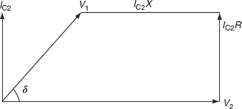
FIG. 10.12 Phasor diagram
We can also find ∣V1∣ from expression ![]() , where Q2 = −Qc because the current is leading and P2 = 0.
, where Q2 = −Qc because the current is leading and P2 = 0.
We are given line voltage at the receiving end, therefore, on per phase, we have

Hence,

Sending-end voltage, line to line
KEY NOTES
- Sources and sinks of a reactive power are synchronous machine, overhead lines, transformers, cables, and loads.
- The voltage-control equipment is located at generating stations, transformer stations, and feeders.
- The various methods for voltage control are: excitation control, shunt capacitors, series capacitors by using tap-changing transformers, boosters, and synchronous condensers.
- Excitation control: This method is used only at the generating station. Due to the voltage drop in the synchronous reactance of armature, whenever the load on the supply system changes, the terminal voltage of the alternator also changes. This can be kept constant by changing the field current of the alternator according to the changes in load. This is known as excitation control.
- Shunt capacitors and reactors: Shunt capacitors are used for lagging p.f. circuits; whereas reactors are used for leading p.f. circuits such as created by lightly loaded cables.
- Series capacitor: It is installed in series with transmission lines to reduce the frequency of voltage drops.
- Tap-changing transformers: The basic operation of a tap-changing transformer is by changing the transformation ratio, the voltage in the secondary circuit is varied.
- Booster transformers: The booster transformer performs the function of boosting the voltage. It can be installed at a sub-station or any intermediate point of line.
- Synchronous condensers: It is connected in parallel with the load at the receiving end of the line. It can either generate or absorb reactive power by varying the excitation of its field winding.
SHORT QUESTIONS AND ANSWERS
- What are the different methods of voltage control?
The following methods are generally employed for controlling the receiving-end voltage.
- By excitation control.
- By using tap-changing transformer.
- Auto-transformer tap changing.
- Booster transformer.
- Induction regulators.
- By synchronous condensers.
- What is meant by excitation voltage control?
Due to the voltage drops in the synchronous reactance of the armature, whenever the load on the supply system changes, the terminal voltage of the alternator changes correspondingly. This can be kept constant by changing the field current of the alternator according to the changes in load.
- What are the disadvantages of tap-changing transformers?
- During switching, the impedance of transformer is increased and there will be a voltage surge.
- There are twice as many tappings as the voltage steps.
- What is the synchronous condenser?
A synchronous motor takes a leading current when overexcited and therefore behaves as a capacitor. An overexcited synchronous motor running on no-load is known as a synchronous condenser.
- What is a booster transformer?
The transformer, which is used to control the voltage of the transmission line at a point far away from the main transformer, is known as booster transformer.
- How does a shunt-capacitor bank control the system voltage under light loads and heavy loads?
The shunt-capacitor bank provided with fixed and variable elements may be either removed from or added to the bank to decrease or increase the capacitance under no-load and heavy-load conditions, respectively.
- Under what condition does a synchronous motor take a leading current?
The synchronous motor takes leading current when its field is overexcited under high-load conditions.
- When is the shunt-inductor compensation required?
The shunt-inductor compensation is required whenever the loading is less than the surge impedance loading.
MULTIPLE-CHOICE QUESTIONS
- The voltage of the power supply at the consumer’s service must be held substantially _____
- Constant.
- Smooth variation.
- Random variation.
- None of these.
- Low voltage reduces the _____ from incandescent lamps.
- Power output.
- Power input.
- Light output.
- Current.
- Motors operated at below normal voltage draw abnormally _____ currents.
- Low.
- High.
- Medium.
- None of these.
- Permissible voltage variation is _____.
- ± 10%.
- ± 20%.
- ±50%.
- ± 5%.
- By drawing high currents at low voltages, the motors get _____.
- Overheated.
- Cool.
- Constant heat.
- None of these.
- Domestic circuits’ supply voltage is _____.
- 230 V.
- 110 V.
- 240 V.
- 220 V.
- The voltage may normally vary between the limits of _____.
- 210 and 230 V.
- 230 and 240 V.
- 230 and 520 V.
- 210 and 235 V.
- Above normal voltages reduces the _____ of the lamps.
- Life.
- Strength.
- Lighting.
- Color.
- The voltage at the bus can be controlled by the injection of _____ power of the correct sign.
- Real.
- Reactive.
- Complex.
- Both real and reactive.
- General methods of voltage control are _____.
- Use of tap-changing transformer.
- Synchronous condensers.
- Static capacitors.
- All of these.
- Use of thyristor-controlled static compensators is _____.
- Voltage control.
- Power control.
- Current control.
- None of these.
- An overexcited synchronous machine operated as generator or motor generates _____
- kVA.
- kVAr.
- kW.
- kI.
- Synchronous motor running at no-load and overexcited load is known as _____
- Synchronous condenser.
- Shunt capacitor.
- Series capacitor.
- None of these.
- The excitation-control method is only suitable for _____ lines.
- Short.
- Medium.
- Long.
- All of these.
- It is _____ to maintain the same voltage at both ends of transmission lines by the synchronous-condenser method.
- Economical.
- Not economical.
- Difficult.
- Easy.
- Shunt capacitors and reactors are used across lightly loaded lines to absorb some of the leading _____ again to control the voltage.
- VArs.
- VA.
- VBRS.
- None of these.
- Disadvantages of shunt capacitors are _____.
- Fall of voltage.
- Reduction in VArs.
- Reduction in effectiveness.
- All of these.
- _____ reduces the inductive reactance between the load and the supply point.
- Shunt capacitor.
- Shunt reactor.
- Series capacitor.
- Transformer.
- The disadvantage of a series capacitor is that it produces _____ voltage across the capacitor under short-circuit condition.
- Low.
- High.
- Very low.
- Either (a) or (b).
- A spark gap with a high-speed contactor is the _____ used for shunt capacitor.
- Protective device.
- Control.
- Fuse.
- Circuit breaker.
- The different types of tap-changing transformers are _____.
- Off-load.
- On-load.
- Both (a) and (b).
- Either (a) or (b).
- The purpose of using booster transformers is _____ the voltage.
- Transforming.
- Bucking.
- Boosting.
- Bucking and boosting.
- More expensive, less efficient, and take more floor area are the disadvantages of the _____ transformer.
- If a synchronous machine gets overexcited, takes lagging VArs from the system when it is operated as a _____.
- Synchronous motor.
- Synchronous generator.
- Either (a) or (b).
- Synchronous phase modifier.
- For a synchronous phase modifier, the load angle is _____.
- 0°.
- 25°.
- 30°.
- 50°.
REVIEW QUESTIONS
- Why is voltage control required in power systems? Mention the different methods of voltage control employed in power system. Explain one method of voltage control in detail giving a neat connection diagram.
- Why is excitation control necessary in an alternator?
- Describe ‘off-load’ and ‘on-load’ tap-changing transformers.
- Explain the function of a synchronous phase modifier placed at the receiving end of the transmission line.
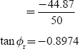
- Show with the aid of a vector diagram, how the voltage at the receiving end of a transmission line can be maintained constant by the use of a synchronous phase modifier.
PROBLEMS
- A 3-ϕ 33-kV overhead transmission line has a resistance of 5 Ω/phase and a reactance of 18 Ω/phase with the help of a synchronous modifier, the receiving-end voltage is kept constant at 33 kV. Calculate the kVA of the phase modifier if the load at the receiving end is 60 MW at 0.85 p.f. lagging. What will be the maximum load that can be transmitted?
- If the voltage at the sending end is to be maintained at 66 kV, determine the MVAr of the phase modifier to be installed for a 3-ϕ overhead transmission line having an impedance of (7 + j 19) Ω/phase, delivering a load of 80 MW at 0.85 p.f. lagging and with voltage 66 kV.
- A 3-ϕ induction motor delivers 450 HP at an efficiency of 95% when the operating p.f. is 0.85 lag. A loaded synchronous motor with a power consumption of 110 kW is connected in parallel with the induction motor. Calculate the necessary kVA and the operating p.f. of the synchronous motor if the overall p.f. is to be unity.