Hydrates are classified by the crystal structure they form. There are three common structures: type I, type II, and type H. The size of the hydrate former molecule dictates which type of hydrate will form. The smallest guest molecules form type II, the intermediate ones for type I, and the largest form Type II. Type H hydrates are only possible with a large former and a smaller molecule. This chapter discusses the common hydrate formers (also known as guest molecules) and gives the range of temperatures and pressure at which the hydrate will form for the pure components that form hydrates. The common hydrate formers include methane, ethane, propane, carbon dioxide, hydrogen sulfide, and nitrogen. Other hydrate formers are simply listed, particularly those of less interest to the natural gas industry.
Keywords
Crystal structure; Formers; Hydrate types; Type H; Type I; Type II
Hydrates of natural gas components and other similar compounds are classified by the arrangement of the water molecules in the crystal, and hence the crystal structure. The water molecules align, because of the hydrogen bonding, into three-dimensional sphere-like structures often referred to as a cage. A second molecule resides inside the cage and stabilizes the entire structure.
There are two types of hydrates commonly encountered in the petroleum business. These are called type I and type II, sometimes referred to as structures I and II. A third type of hydrate that also may be encountered is type H (also known as structure H), but it is less commonly encountered.
Table 2.1 provides a quick comparison among type I, type II, and type H hydrates. These hydrates will be reviewed in more detail throughout this chapter.
Figure 2.1 shows the types of polyhedral cages involved in type I and II hydrates. In these diagrams, the water molecule is on the corner of the polyhedral, and the edge of the polyhedral represents the hydrogen bond. The structures for the type H hydrate, being significantly more complex, are not described in such detail, except to note that the small cages are the regular dodecahedron. The information in Table 2.1 and Fig. 2.1 will become clearer as the reader covers the entire chapter.
2.1. Type I Hydrates
The simplest of the hydrate structures is the type I. It is made from two types of cages: (1) dodecahedron, a 12-sided polyhedron where each face is a regular pentagon and (2) tetrakaidecahedron, a 14-sided polyhedron with 12 pentagonal faces and 2 hexagonal faces. The dodecahedral cages are smaller than the tetrakaidecahedral cages; thus, the dodecahedra are often referred to as small cages whereas the tetrakaidecahedral cages are referred to as large cages.
Type I hydrates consist of 46 water molecules. If a guest molecule occupies each of the cages then the theoretical formula for the hydrate is X⋅534H2O, where X is the hydrate former.
Table 2.1
Comparisons among Type I, Type II, and Type H Hydrates
1X is the hydrate former and Y is a type H former.
Figure 2.1The Polyhedral Cages of Type I and Type II Hydrates.
Often, in the literature, you will find oversimplifications for the hydrate crystal structure. For example, it is common that only the dodecahedron is given as the unit crystal structure. This is incorrect. The correct structures are given here.
One of the reasons why it took a long time to establish the crystal structure of hydrates is because hydrates are nonstoichiometric. That is, a stable hydrate can form without a guest molecule occupying all of the cages. The degree of saturation is a function of the temperature and the pressure. Therefore, the actual composition of the hydrate is not the theoretical composition given in the previous paragraph.
2.1.1. Type I Formers
Some of the common type I hydrate formers include methane, ethane, carbon dioxide, and hydrogen sulfide. In the hydrates of CH4, CO2, and H2S, the guest molecules can occupy both the small and the large cages. On the other hand, the ethane molecule occupies only the large cages.
2.2. Type II Hydrates
The structure of the type II hydrates is significantly more complicated than that of type I. The type II hydrates are also constructed from two types of cages. The unit structures of a type II hydrate are: (1) dodecahedron, a 12-sided polyhedron where each face is a regular pentagon, (2) hexakaidecahedron, a 16-sided polyhedron with 12 pentagonal faces and 4 hexagonal faces. The dodecahedral cages are smaller than the hexakaidecahedron cages.
The type II hydrate consists of 136 molecules of water. If a guest molecule occupies all of the cages, then the theoretical composition is X⋅523H2O, where X is the hydrate former. Alternatively, as is more commonly the case, if the guest occupies only the large cages, then the theoretical composition is X·17H2O.
As with type I hydrates, the type II hydrates are not stoichiometric, so the compositions of the actual hydrates differ from the theoretical values.
2.2.1. Type II Formers
Among the common type II formers in natural gas are nitrogen, propane, and isobutane. It is interesting that nitrogen occupies both the large and small cages of the type II hydrate. On the other hand, propane and isobutane only occupy the large cages.
2.3. Type H Hydrates
Type H hydrates are much less common than either type I or II. In order to form this type of hydrate, it requires a small molecule, such as methane, and a type H former. As such, type H hydrates are always double hydrates.
The type H hydrates are constructed from three types of cages: (1) dodecahedron, a 12-sided polyhedron where each face is a regular pentagon, (2) an irregular dodecahedron with 3 square faces, 6 pentagonal faces, and 3 hexagonal faces, and (3) an irregular icosahedron, a 20-sided polyhedron, with 12 pentagonal faces and 8 hexagonal faces.
The unit crystal is made up of three dodecahedral cages (small), two irregular dodecahedral cages (medium), and one icosahedral cage (large). It is composed of 34 water molecules.
Type H hydrates are always double hydrates. Small guest molecules, such as methane, occupy the small, medium, and some of the large cages of the structure whereas a larger molecule, such as those given below, occupies the large cage. The larger molecule, the so-called type H former, is of such a size that it only fits in the large cage of this structure.
Because two formers are required to form a type H hydrate, it is a little difficult to give the theoretical formula. However, if we assume that the small molecule, X, only enters the two smaller cages and we know that the large molecule, Y, only enters the large cages, then the theoretical formula is Y·5X·34H2O.
2.3.1. Type H Formers
Type I and II hydrates can form in the presence of a single hydrate former, but type H requires two formers to be present, a small molecule, such as methane, and a larger type H forming molecule.
Type H formers include the following hydrocarbon species: 2-methylbutane, 2,2-dimethylbutane, 2,3-dimethylbutane, 2,2,3-trimethylbutane, 2,2-dimethylpentane, 3,3-dimethylpentane, methylcyclopentane, ethylcyclopentane, methylcyclohexane, cycloheptane, and cyclooctane. Most of these components are not commonly found in natural gas; or perhaps it is better to state that most analyses do not test for these components.
2.4. The Size of the Guest Molecule
Von Stackelberg (1949) discovered the relationship between the size of a molecule and the type of hydrate formed. He plotted a chart, reproduced here, after some modifications, as Fig. 2.2, showing the nature of the hydrate based on the size of the guest molecule.
At the top of the diagram are the small molecules and the size increases as one goes downward on the chart. Hydrogen and helium are the smallest molecules with diameters of only 2.7 and 2.3Å, respectively (note 1Å=1×10⁻¹⁰m). From the chart it can be seen that molecules with diameters less than about 3.8Å do not form hydrates.
As molecules increase in size, that is as we move down the chart, we come upon the first hydrate formers, which include krypton and nitrogen. There is a region bounded by two rather broad hash marks and molecules with sizes in this range (from about 3.8 to 4.2Å) that form type II hydrates. These substances are sufficiently small such that they can occupy both the small and the large cages of this hydrate structure.
Figure 2.2Comparison of Guest Size, Hydrate Type, and Cavities Occupied for Various Hydrate Formers.Modified from original by von Stackelberg (1949).
Even further down the chart is the next region (ranging from approximately 4.4–5.4Å), which includes methane, hydrogen sulfide, and carbon dioxide. Molecules with sizes in this range are type I formers and the molecules are small enough to occupy both the small and the large cages.
Molecules that are larger still occupy the next region on the chart (from about 5.6 to 2.8Å). The region is quite narrow and the only important substance in it is ethane. Compounds with sizes in this range form type I hydrates, but they only occupy the large cages. These molecules are too large to enter the small cages of a type I hydrate.
The next region, which represents even larger molecules (ranging from about 6.0 to 6.9Å), contains propane and isobutane. These molecules are type II formers but only occupy the large cages of the type II structure. Molecules with sizes in this range are too large to enter the small cages of a type II hydrate.
Eventually, a limited is reached. Molecules larger than about 7Å do not form either a type I or type II hydrate. Therefore, molecules such as pentane, hexane, and larger paraffin hydrocarbons are non-formers.
From the chart, we can see that cyclopropane (c-C3H8) and n-butane are in the hatched regions. These special components will be discussed in more detail later in this chapter.
Slightly larger molecules can form type H hydrates, but the maximum size for these compounds to form a hydrate is about 9Å.
2.5. n-Butane
In the study of hydrates, n-butane is an interesting anomaly (Ng and Robinson, 1976). By itself, n-butane does not form a hydrate. However, its size is such that it can fit into the large cages of the type II hydrate lattice. Thus, in the presence of another hydrate former, n-butane can enter the cages.
It is based on the observed behavior of n-butane that the location of the last hatched section is established. n-Butane is a transition component. Molecules smaller than n-butane are hydrate formers, whereas molecules larger than n-butane do not form type I or type II hydrates.
2.6. Other Hydrocarbons
Other types of hydrocarbons (alkenes and alkynes, for example) also form hydrates, provided they are not too large. Compounds such as ethylene, acetylene, propylene, and propyne are hydrate formers.
Other hydrocarbons are special cases and they will be discussed in subsequent sections of this chapter.
2.7. Cyclopropane
Cyclopropane is another interesting case. It can form either a type I or II hydrate. The type of hydrate formed depends on the temperature and the pressure (Hafemann and Miller, 1969; Majid et al., 1969).
Regardless of the type of hydrate formed, cyclopropane is of such a size that it only enters the large cages.
This unusual behavior makes cyclopropane a transition component. Cyclopropane is the boundary between type I (large cage only) and type II (large cages only) formers.
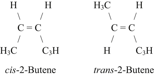
2.8. 2-Butene
The geometric isomers of 2-butene are also an interesting case. The two isomers of 2-butene are:
Like n-butane, they are too large to form hydrates on their own; however, in a mixture with methane, hydrates do form. However, the trans isomer behaves like n-butane, inasmuch as it will enter the hydrate lattice in the presence of hydrate formers. On the other hand, the cis isomer is too large to enter the hydrate lattice. Mixtures of methane+trans-2-butene form a type II hydrate with the trans-2-butene entering the large cages of the type II lattice. Mixtures of methane+cis-2-butene form a type I hydrate because this isomer is not capable of entering the lattice. For evidence of this behavior, see Holder and Kamath (1984).
2.9. Hydrogen and Helium
As was mentioned earlier, hydrogen and helium are small gases that are known to be non-formers of hydrates. Even when they are in a mixture with hydrate formers present, they do not enter the hydrate lattice in spite of their small size.
It is believed that van der Waals forces between the guest and the host molecules are the reason for the stabilization of the hydrate crystal. Furthermore, the van der Waals forces are believed to be a result of the electrons in a compound. Hydrogen (H2) and helium have only two electrons per molecule and, thus, the van der Waals forces are weak. This is one explanation why these small molecules do not form hydrates.
2.9.1. Update
New evidence shows that under extreme pressure hydrogen does indeed form a hydrate (Mao and Mao, 2004). The pressures required are 200–300MPa (29,000–43,500psia) for temperatures in the range from 240 to 249K (−33 to −24°C, –28° to −11°F). Such a hydrate was found to be type II, which is as expected based on the chart of von Stackelberg discussed earlier. However, an unusual feature is that two hydrogen atoms enter the individual hydrate cages.
Notwithstanding those observations, for almost all engineering applications hydrogen can be considered a non-former, which does not enter the hydrate cages.
2.10. Chemical Properties of Potential Guests
Another limiting factor is the chemical properties of the potential hydrate former. A molecule may be sufficiently small but it may not form a hydrate. Typically, if a gas is highly soluble in water, it will not form a hydrate.
It has been shown that CO2 and H2S, which have significant solubility in water, form hydrates. In addition, SO2, which is quite soluble in water, is also a hydrate former. As a rule of thumb, these represent the upper limit in terms of solubility. Gases that are highly soluble in water, such as ammonia and hydrogen chloride, do not form hydrates even though their size might lead one to believe that they should.
Alternatively, if the molecule interferes with the hydrogen bonding, a hydrate will not form. Methanol, which is a small molecule, does not form a hydrate because it is hydrogen bonded and, hence, interferes with the hydrogen bonding among the water molecules. In addition, methanol is highly soluble in water. We will return to the subject of methanol and its importance in the formation of hydrates later on in this chapter.
2.11. Liquid Hydrate Formers
It is a commonly held belief that hydrates do not form in the presence of a nonaqueous liquid phase. That is, that hydrates will not form in the presence of condensate or oil. This is not true. Many experimental investigations demonstrate that liquid hydrocarbons can indeed form hydrates. As discussed briefly in Chapter 1, all that is required is the presence of a hydrate former, enough water present to form a hydrate, and the right combination of pressure and temperature. No mention was made of the phase of the former.
There is an unfortunate habit of referring to these compounds as “gas hydrates.” This leaves the impression that they form only with gases.
2.12. Hydrate Forming Conditions
Experimental investigations have been done for almost all of the common components in natural gas. These results are summarized in the book by Sloan (1998). It would be wise for the reader to search the literature for experimental data when there is any doubt about the hydrate forming conditions for a specific component or mixture. The book by Sloan (1998) is a good place to start.
2.12.1. Pressure–Temperature
The following tables show the pressure and temperature at which a hydrate will form for the common hydrate formers in natural gas. Table 2.2 gives the data for methane, Table 2.3 for ethane, Table 2.4 for propane, Table 2.5 for isobutane, Table 2.6 for hydrogen sulfide, and Table 2.7 for carbon dioxide.
Table 2.2
Hydrate Forming Conditions for Methane
Temperature (°C)
Pressure (MPa)
Phases
Composition (mol%)
Aqueous
Vapor
Hydrate
0.0
2.60
LA–H–V
0.10
0.027
14.1
2.5
3.31
LA–H–V
0.12
0.026
14.2
5.0
4.26
LA–H–V
0.14
0.026
14.3
7.5
5.53
LA–H–V
0.16
0.025
14.4
10.0
7.25
LA–H–V
0.18
0.024
14.4
12.5
9.59
LA–H–V
0.21
0.024
14.5
15.0
12.79
LA–H–V
0.24
0.025
14.5
17.5
17.22
LA–H–V
0.27
0.025
14.5
20.0
23.4
LA–H–V
0.30
0.027
14.6
22.5
32.0
LA–H–V
0.34
0.028
14.6
25.0
44.1
LA–H–V
0.37
0.029
14.7
27.5
61.3
LA–H–V
0.41
0.029
14.7
30.0
85.9
LA–H–V
0.45
0.029
14.7
Composition for aqueous phase and for the hydrate is the mole percent of the hydrate former (CH4). For the vapor, the composition is the mole percent water.
Table 2.3
Hydrate Forming Conditions for Ethane
Temperature (°C)
Pressure (MPa)
Phases
Composition (mol%)
Aqueous
Nonaqueous
Hydrate
0.0
0.53
LA–H–V
0.037
0.126
11.5
2.0
0.61
LA–H–V
0.041
0.117
11.5
4.0
0.77
LA–H–V
0.047
0.107
11.5
6.0
0.99
LA–H–V
0.054
0.096
11.5
8.0
1.28
LA–H–V
0.062
0.086
11.5
10.0
1.68
LA–H–V
0.072
0.075
11.5
12.0
2.23
LA–H–V
0.083
0.065
11.5
14.0
3.10
LA–H–V
0.096
0.052
11.5
14.6
3.39
LA–LH–V–H
0.098
0.049-V 0.025-LH
11.5
15.0
4.35
LA–LH–H
0.098
0.025
11.5
16.0
10.7
LA–LH–H
0.103
0.023
11.5
16.7
15.0
LA–LH–H
0.105
0.022
11.5
17.5
20.0
LA–LH–H
0.106
0.022
11.5
Composition for the aqueous phase and for the hydrate is the mole percent of the hydrate former (C2H6). For the nonaqueous phase (either the vapor or a second liquid), the composition is the mole percent water. The phase designated LH is a C2H6-rich liquid.
Table 2.4
Hydrate Forming Conditions for Propane
Temperature (°C)
Pressure (MPa)
Phases
Composition (mol%)
Aqueous
Nonaqueous
Hydrate
0.0
0.17
LA–H–V
0.012
0.36
5.55
1.0
0.21
LA–H–V
0.014
0.31
5.55
2.0
0.26
LA–H–V
0.017
0.27
5.55
3.0
0.32
LA–H–V
0.019
0.23
5.55
4.0
0.41
LA–H–V
0.023
0.19
5.55
5.0
0.51
LA–H–V
0.027
0.17
5.55
5.6
0.55
LA–LH–V–H
0.028
0.158-V 0.0094-LH
5.55
5.6
1.0
LA–LH–H
0.028
0.0093
5.55
5.6
5.0
LA–LH–H
0.028
0.0088
5.55
5.7
10.0
LA–LH–H
0.028
0.0083
5.55
5.7
15.0
LA–LH–H
0.028
0.0079
5.55
5.7
20.0
LA–LH–H
0.028
0.0074
5.55
Composition for aqueous phase and for the hydrate is the mole percent of the hydrate former (C3H8). For the nonaqueous phase (either the vapor or a second liquid), the composition is the mole percent water. The phase designated LH is a C3H8-rich liquid.
Table 2.5
Hydrate Forming Conditions for Isobutane
Temperature (°C)
Pressure (MPa)
Phases
Composition (mol%)
Aqueous
Nonaqueous
Hydrate
0.0
0.11
LA–H–V
0.0058
0.55
5.55
0.5
0.12
LA–H–V
0.0062
0.52
5.55
1.0
0.14
LA–H–V
0.0070
0.46
5.55
1.5
0.15
LA–H–V
0.0082
0.39
5.55
1.8
0.17
LA–LH–V–H
0.0081
0.40-V 0.0067-LH
5.55
2.0
0.5
LA–LH–H
0.0080
0.0067
5.55
2.3
1.0
LA–LH–H
0.0079
0.0068
5.55
2.3
2.0
LA–LH–H
0.0079
0.0067
5.55
2.4
4.0
LA–LH–H
0.0079
0.0066
5.55
2.4
6.0
LA–LH–H
0.0079
0.0064
5.55
2.5
8.0
LA–LH–H
0.0079
0.0063
5.55
2.5
10.0
LA–LH–H
0.0079
0.0063
5.55
2.7
15.0
LA–LH–H
0.0077
0.0060
5.55
2.8
20.0
LA–LH–H
0.0076
0.0057
5.55
Composition for aqueous phase and for the hydrate is the mole percent of the hydrate former (i-C4H10). For the nonaqueous phase (either the vapor or a second liquid), the composition is the mole percent water. The phase designated LH is an i-C4H10-rich liquid. Values for the compositions of the non-hydrate phases are preliminary.
Table 2.6
Hydrate Forming Conditions for Hydrogen Sulfide
Temperature (°C)
Pressure (MPa)
Phases
Composition (mol%)
Aqueous
Nonaqueous
Hydrate
0.0
0.10
LA–H–V
0.37
0.62
14.2
5.0
0.17
LA–H–V
0.52
0.54
14.3
10.0
0.28
LA–H–V
0.74
0.46
14.4
15.0
0.47
LA–H–V
1.08
0.38
14.5
20.0
0.80
LA–H–V
1.58
0.32
14.6
25.0
1.33
LA–H–V
2.28
0.28
14.6
27.5
1.79
LA–H–V
2.84
0.25
14.7
29.4
2.24
LA–LS–V–H
3.35
0.24-V 1.62-LS
14.7
30.0
8.41
LA–LS–H
3.48
1.69
14.7
31.0
19.49
LA–LS–H
3.46
1.77
14.7
32.0
30.57
LA–LS–H
3.41
1.83
14.7
33.0
41.65
LA–LS–H
3.36
1.88
14.7
Composition for aqueous phase and for the hydrate is the mole percent of the hydrate former (H2S). For the nonaqueous phase (either the vapor or a second liquid), the composition is the mole percent water. The phase designated LS is an H2S-rich liquid.
Table 2.7
Hydrate Forming Conditions for Carbon Dioxide
Temperature (°C)
Pressure (MPa)
Phases
Composition (mol%)
Aqueous
Nonaqueous
Hydrate
0.0
1.27
LA–H–V
1.46
0.058
13.8
2.0
1.52
LA–H–V
1.67
0.056
13.9
4.0
1.94
LA–H–V
1.92
0.053
13.9
6.0
2.51
LA–H–V
2.21
0.051
14.1
8.0
3.30
LA–H–V
2.54
0.049
14.2
9.8
4.50
LA–LC–V–H
2.93
0.051-V 0.21-LC
14.2
10.0
7.5
LA–LC–H
2.97
0.22
14.5
10.3
10.0
LA–LC–H
3.0
0.24
14.7
10.8
15.0
LA–LC–H
3.1
0.25
14.7
11.3
20.0
LA–LC–H
3.1
0.27
14.7
Composition for aqueous phase and for the hydrate is the mole percent of the hydrate former (CO2). For the nonaqueous phase (either the vapor or a second liquid), the composition is the mole percent water. The phase designated LC is a CO2-rich liquid.
The table for methane has been somewhat arbitrarily limited to 30°C (86°F). At this temperature, the hydrate formation pressure is 85.9MPa (12,460psia) and this pressure is probably a limit to that encountered in normal petroleum operations. It is worth noting that experimental data show that the methane hydrate does form at temperatures greater than 30°C. In fact, the hydrate can be observed at the highest pressures measured in the laboratory.
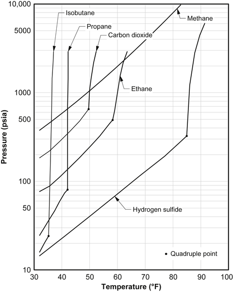
The pressure–temperature loci for these hydrate formers are shown in Fig. 2.3 in SI units and in Fig. 2.4 in American engineering units. These are the same values as those presented in the tables mentioned earlier.
In every case, the three-phase loci involving two liquid phases are very steep. Small changes in the temperature have a dramatic effect on the pressure. This is clearly seen in Fig. 2.3. Methane does not have such a locus.
2.12.2. Composition
The compositions for the various phases: aqueous liquid, hydrate, nonaqueous liquid, and vapor, are also given in these tables.
Note that for ethane, propane, and isobutane, the compositions of the hydrate does not appear to be a function of the temperature or the pressure (i.e., they are constant). The reason for this is that these molecules only enter the large cages of their respective hydrate, and in the large cages there is a high degree of occupancy. The values given in the tables are essentially the 100% saturation values.
Figure 2.3The Hydrate Loci for Several Components Found in Natural Gas.
The compositions for the aqueous phase, the vapor, and, if it exists, the nonaqueous liquid were calculated using AQUAlibrium 2.1 The compositions of the hydrate are estimated from a combination of experimental data, computer software, and the crystal structure of the hydrate.
The water content of the nonaqueous phases is given in different units in Appendix A.
The reader should not read too much into the magnitudes of the compositions of the nonaqueous phases. For example, it appears as though methane is the most soluble of the hydrocarbons listed. The values listed show significantly larger concentrations in the aqueous phase. However, the solubility is a function of the temperature and the pressure and the values for methane are at higher pressures than the other hydrocarbons.
Figure 2.4The Hydrate Loci for Several Components Found in Natural Gas (American Engineering Units).
Details about how the composition affects whether or not a hydrate will form are discussed in Chapter 9, which is on phase diagrams.
2.12.3. Caution
The values in these tables are not experimental data and should not be substituted for experimental data. It is useful to compare these values to experimental values, but it would be unwise to build correlations based upon these values. These tables are for use in engineering calculations.
Figure 2.5Hydrate Loci for Methane and Nitrogen.
2.12.4. Nitrogen
Figure 2.5 shows the hydrate locus for nitrogen. For comparison purposes, the hydrate locus of methane is also plotted. Note that significantly higher pressures are required to form a hydrate with nitrogen than with methane.
2.12.5. Ethylene
The hydrate locus for ethylene has been investigated several times. The hydrate locus for ethylene is plotted on Fig. 2.6. The shape of the hydrate locus is a little unusual, when compared with the hydrate loci of other common hydrate forming gases, such as methane, ethane, propane, carbon dioxide, and hydrogen sulfide. At first, it appears that perhaps there is a liquid-liquid-hydrate-vapor quadruple point at about 18°C (64°F). However, the system ethylene+water does not have such a point. The hydrate locus passes through the pressure-temperature plane beyond the critical point of ethylene (9°C and 5060kPa).
Another possible explanation for the shape of the curve is that possibly the hydrate changes crystal structure at about 18°C. The somewhat unusual shape of the hydrate locus can simply be explained in terms of the fluid properties of ethylene.
Figure 2.6Hydrate Formation Condition for Ethylene.
2.12.6. Propylene
The hydrate locus of propylene is very short, only 1°C (1.8°F), in fact, many researchers had difficulty finding this locus. Accurate data were obtained by Clarke et al. (1964) and they established that the locus extended from −0.16 to +0.96°C. The hydrate locus for propylene is shown in Fig. 2.7.
Above about 1°C, the hydrate is formed with liquid propylene and the LH–LA–H locus is quite steep. There have been no studies of this locus.
2.13. V+LA+H Correlations
The most commonly encountered hydrate forming conditions are those involving a gas, an aqueous liquid, and the hydrate.
Figure 2.7Hydrate Forming Conditions for Propylene.
The experimental vapor-aqueous liquid-hydrate loci were correlated using the following equation:
lnP=A+BT+C/T+DlnT
(2.1)
where T is in Kelvin and P is in MPa. This is a semiempirical equation, which has its basis in the Clausius–Clapeyron equation. The coefficients, A, B, C, and D, for the various gases are summarized in Table 2.8. The correlation for hydrogen sulfide is taken from Carroll and Mather (1991), the correlation for propylene and acetylene are from Carroll (2006), and those for the other gases are from Carroll and Duan (2002).
2.13.1. Ethylene
An attempt was made to correlate the pressure and temperature using the usual approach of correlating the pressure (or the logarithm of the pressure) as a function of the temperature, such as those presented earlier for the components of natural gas. This approach was not very successful. It was found that a better correlation was obtained by correlating the temperature as a function of the pressure. The resulting expression is:
1T=∑4i=0ai(lnP)i
(2.2)
where the temperature is in Kelvin and the pressure is in MPa and the polynomial coefficients are:
a0=+3.585 2538×10−3
a1=−1.241 3537×10−4
a2=+3.090 7775×10−5
a3=−3.416 2547×10−6
a4=−1.121 0772×10−7
This correlation is valid for the temperature range from 0 to 55°C, or for pressures from about 0.5 to 500MPa. This function is the curve plotted in Fig. 2.6.
As was mentioned earlier, the shape of the hydrate locus for ethylene is a little unusual. To demonstrate this further, Fig. 2.8 shows the hydrate loci for methane, ethane, and ethylene. At low temperature, the hydrate loci of ethane and ethylene are quite similar. However, at about 15°C, the ethane locus has a quadruple point. This is approximately the point where the hydrate locus intersects the vapor pressure curve of pure ethane. At temperatures beyond this point, the hydrate locus rises very steeply. Ethylene has no such quadruple point.
At higher temperatures (greater than about 25°C), the hydrate loci of methane and ethylene are similar (at least up to about 100MPa).
Table 2.8
Summary of the Correlation Coefficients for Eqn 2.1
A
B
C
D
Methane
−146.1094
+0.3165
+16,556.78
0
Ethane
−278.8474
+0.5626
+33,996.53
0
Propane
−259.5822
+0.5800
+27,150.70
0
Isobutane
+469.1248
−0.7523
−72,608.26
0
Propylene
+63.2863
0
−17,486.30
0
Acetylene
+34.0727
0
−9428.80
0
CO2
−304.7103
+0.6138
+37,486.96
0
N2
+26.1193
+0.0103
−7141.92
0
H2S
−19.9874
+0.1514
+2788.88
−3.5786
Figure 2.8Hydrate Loci for Methane, Ethane, and Ethylene.
More discussion of the somewhat unusual behavior of the ethylene hydrate locus is given in the study by Carroll (2006).
2.14. LA+LN+H Correlations
It is somewhat unfortunate that it is common to refer to these solids as “gas hydrates” because it is possible for hydrates to form in the presence of liquids. Not only is it possible, it is common. Ethane, propane, and isobutane all form hydrates in the liquid form. Therefore, it is possible for liquefied petroleum gas (LPG) to form hydrates.
The hydrate locus for the liquid-liquid-hydrate region is much more difficult to correlate than the V+LA+H locus. The first problem is that the data are a little less reliable. Second, these loci tend to be very steep (dP/dT is very large). For these reasons, a simpler equation was used for this locus:
P=E+FT
(2.3)
where P is in MPa and T is in Kelvin. For the substances considered here, the coefficients are listed in Table 2.9. The values for hydrogen sulfide are from Carroll and Mather (1991) and the others were determined as a part of this study.
Table 2.9
Summary of the Correlation Coefficients for Eqns (2.2)–(2.3)
E
F
Ethane
−1831.10
6.370
Isobutane
−9218.60
33.478
CO2
−2604.71
9.226
H2S
−3352.515
11.083
Unfortunately, the data for propane are poor and a good correlation was not obtained.
2.15. Quadruple Points
The intersection of four three-phase loci is a quadruple point. Table 2.10 summarizes the quadruple points for hydrate formers commonly encountered in natural gas. Most of these values were taken from Sloan (1998), with the exception of H2S, which was taken from Carroll and Mather (1991), and propylene that is from Clarke et al. (1964).
The quadruple points are noted by the phases that are in equilibrium. The phase designations used are as follows: LA=aqueous liquid, V=vapor, I=ice, H=hydrate, and LH=nonaqueous liquid (this includes the LS and LC used earlier).
Table 2.10
Quadruple Points for Common Components in Natural Gas
Note that neither methane nor nitrogen has the second type of quadruple point (LA–LH–V–H). That is because neither of these gases liquefy at the conditions required to form such a quadruple point.
The compositions of the coexisting phases at the second quadruple point (LA–LH–V–H) are given in the tables presented earlier.
The first of these quadruple points is approximately where the hydrate locus intercepts the melting curve of pure water. Thus, they are all at approximately 0°C. The exception to this is the nitrogen quadruple point, which is at an elevated pressure and a lower temperature.
The second quadruple point is approximately where the hydrate locus intercepts the vapor pressure curve of the pure hydrate former. As mentioned earlier, because the vapor pressure curves of nitrogen and methane do not extend to these temperatures, they do not exhibit the second quadruple point.
2.15.1. Cyclopropane
Because cyclopropane can form both type I and II hydrates, it has several quadruple points. Table 2.11 lists four quadruple points for cyclopropane.
2.16. Other Hydrate Formers
Although the main focus of this work is the hydrates of natural gas, it is worth noting that many other compounds form hydrates.
2.16.1. Freons®
Freons, organic compounds of chlorine and fluorine, were once commonly used as refrigerants. Because of environmental concerns, their use has been curtailed. However, many of the Freons are hydrate formers, especially the smaller ones (Chinworth and Katz, 1947). It is likely that the newer, more environmentally friendly Freons are also hydrate formers. Therefore, hydrate formation may be a problem in a refrigeration loop if it is not dry.
The name Freon is a registered trademark of the E.I. du Pont de Nemours & Company (DuPont) of Wilmington, Delaware.
2.16.2. Halogens
The halogens are the elements in column 7A of the periodic table (see the appendix to Chapter 1). Of these elements, chlorine and bromine are known hydrate formers. It is likely that fluorine also forms a hydrate based on its size and chemical properties. Historically, chlorine was the first component definitely shown to form a hydrate.
Iodine, another halogen, can form a hydrate only in the presence of another hydrate former (similar to n-butane).
2.16.3. Noble Gases
The following noble gases (the rightmost group in the periodic table), also called inert gases, argon, krypton, xenon, and radon, all form hydrates. As was mentioned earlier, helium, another of the noble gases, does not form a hydrate. It is unlikely that neon, also a small gas, forms a hydrate.
This group of gases is remarkable for their chemical stability. Only under extreme conditions can they be made to react to form compounds. The fact that they form hydrates is a good indication that there is no chemical bonding between the host and guest molecules in a hydrate.
2.16.4. Air
Among the other important compounds that form a hydrate is oxygen. Because it is known that nitrogen also forms a hydrate, then air also forms a hydrate. Both oxygen and nitrogen form hydrates at very high pressures and, for this reason, it was once thought that they did not form hydrates.
A question that is frequently asked is that if air can form a hydrate, is any of the “ice” on the surface of the Earth composed of air hydrate? The answer is no. It requires very high pressure for the components of air to form hydrates (see Fig. 2.4 for the conditions required to form a nitrogen hydrate). Such pressures do not exist on the surface of the Earth.
2.16.5. Others
Sulfur dioxide also forms a hydrate. This is somewhat surprising because SO2 is fairly soluble in water. This is probably the most soluble component that still forms a hydrate. As a rule of thumb, gases more soluble than SO2 do not form hydrates.
Small mercaptans, such as methanethiol, ethanethiol, and possibly propanethiol, are also hydrate formers.
Another interesting compound that forms a hydrate is ethylene oxide. Ethylene oxide is an important industrial chemical, usually as a precursor to other chemicals.
Other hydrate formers include N2O, H2Se, SF6, PH3, AsH3, SbH3, and ClO3F. Obviously, this list of compounds is of little interest to the natural gas industry. It is interesting to see the wide spectrum of components that do form hydrates.
2.17. Hydrate Formation at 0°C
In an attempt to make a simple comparison between the various hydrate formers, the components in natural gas and other hydrocarbons, in particular, it was decided to form a common database. The question arose, what would be the best reference point for such a database. The quadruple point initially seems like a good reference, but methane and nitrogen do not have a LA–LH–V–H quadruple point, which immediately eliminates this point. The other quadruple point might be a good reference, but there is a slight variation in the temperature. Although not important by itself, why not eliminate the temperature variation simply by selecting the hydrate pressure at 0°C as the reference.
Thus, a database was established for the hydrate formation at 0°C. The hydrate pressure for several components at this temperature are given in Table 2.12 along with several physical properties of the various hydrate formers. The densities given in Table 2.12 were calculated with the Peng–Robinson equation of state. In addition, carbon dioxide does not have a normal boiling point, at atmospheric pressure it sublimes. The boiling point in Table 2.12 for CO2 was estimated by extrapolating the vapor pressure.
Also given in Table 2.12 is the solubility of the various gases at 0°C and a gas partial pressure of 1atm. The values were taken from the review paper of Wilhelm et al. (1977). From the values given, it can be seen that there is no correlation between the solubility and the hydrate formation temperature.
2.18. Mixtures
Although the behavior of pure formers is interesting, usually, in industrial practice, we must deal with mixtures. What type of hydrate is formed in a mixture? What is the effect when a non-former is in the mixture?
Table 2.12
Physical Properties and Hydrate Formation of Some Common Natural Gas Components
†Carbon dioxide does not have a normal boiling point. This value is estimated from the vapor pressure.
We have already encountered one interesting situation that arises with a mixture and that was the behavior of n-butane.
2.18.1. Mixtures of the Same Type
As a rule of thumb, if the gas mixture contains hydrate formers of only one type, then the hydrate formed will be of that type. Therefore, for example, a mixture of methane, hydrogen sulfide, and carbon dioxide, all type I formers, will form a type I hydrate. However, the behavior of hydrates is both complex and surprising. One day someone will probably discover a pair of type I formers that form a type II mixture.
One of the interesting things about hydrates is their unusual behavior. The behavior of mixtures is another example. Recently, Subramanian et al. (2000) showed that mixtures of methane and ethane, each that form type I as a pure former, forms type II in the range 72–99.3% methane.
2.18.2. Type I Plus Type II
However, if the mixture contains a type I former and a type II former, what is the nature of the hydrate formed? The thermodynamically correct response to this is that the hydrate formed is the one that results in a minimization of the free energy of the system. That is, the type formed by the mixture is the one that is thermodynamically stable. This is useful from a computational point of view, but fairly useless from a practical point of view. However, there are no hard and fast rules; each case must be examined on its own.
Holder and Hand (1982) studied the hydrate formation conditions in mixtures of ethane, a type I former, and propane, a type II former. They developed a map, reproduced here as Fig. 2.9, showing which regions each type of hydrate would form. As an approximation of their results, if the mixture is greater than 80% ethane, then the hydrate is type I, otherwise it is type II. When the hydrate is type I, the propane does not enter the crystal lattice, only the ethane does.
On the other hand, mixtures of methane, a type I former, and propane, a type II former, almost always form a type II. Only mixtures very rich in methane (99+%) will form a type I hydrate. This conclusion is based largely on the advanced hydrate models that will be discussed in Chapter 4.
2.18.3. Azeotropy
Another interesting phenomenon is the possibility of an “azeotropic” hydrate, which is a hydrate that forms at either a pressure greater than the pressures at which the pure components form hydrates or at a lower pressure than for the pure components.
Figure 2.9Hydrate Formation Map for Mixtures of Ethane and Propane.Based on Holder and Hands (1982).
For example, the hydrate in a mixture of hydrogen sulfide+propane forms at lower pressure than in either pure hydrogen sulfide or pure propane (Platteeuw and van der Waals, 1959). Using the computer software CSMHYD,2 the hydrate pressure for pure H2S at 3°C is estimated to be 145kPa and for pure propane it is 318kPa. However, an equimolar mixture of the two is estimated to form a hydrate at only 64kPa, which is significantly lower than those for the pure components.
It is worth noting that the system propane–hydrogen sulfide exhibits azeotropy in the traditional vapor–liquid sense as well (Carroll and Mather, 1992). It is probable that this is the reason that the hydrate also exhibits azeotropy.
2.18.4. Mixtures with Non-formers
Another important type of mixture is created when one of the components is a non-former. This is the more commonly encountered situation in industrial practice. We usually are not considering only mixtures containing hydrate formers.
It is difficult to generalize about the effect of non-formers. One problem with non-formers is that they tend to be heavy hydrocarbons, and thus will tend to liquefy at the conditions where a hydrate might be encountered. The hydrate formation conditions in a mixture of methane and pentane, a non-former, are governed by the potential of the mixture to liquefy as they are by the conditions at which pure methane forms a hydrate. Not that a liquid does not form a hydrate, but it is formed under different conditions than a gas.
Furthermore, there may be an azeotropic effect between the former and the non-former. Therefore, the hydrate formation pressure may not follow any simple rules of thumb.
Examples
Example 2.1
Will a hydrate form for methane at a temperature of 15°C and 30MPa?
Answer: From Table 2.2, we see that a hydrate of methane forms at a pressure of 12.79MPa at 15°C. Because 30MPa is greater than 12.79MPa, then we conclude that a hydrate will form.
Example 2.2
Will a hydrate form for ethane at a temperature of 10°C and 0.5MPa?
Answer: From Table 2.3, we see that a hydrate of ethane forms at a pressure of 1.68MPa at 10°C. Because 0.5MPa is less than 1.68MPa, then we conclude that a hydrate will not form.
Example 2.3
Will a hydrate form for propane at a temperature of 20°C and 10MPa?
Answer: From Table 2.4, we can safely assume that a propane hydrate will not form at 20°C regardless of the pressure (within reason). The temperature is too high for a hydrate to form (also see Fig. 2.3.)
Example 2.4
At what temperature will a hydrate form for pure methane at a pressure of 1000psia? Also, what are the compositions of the coexisting phases at this pressure? Express the water content of the gas in pounds per million standard cubic feet (lb/MMCF).
Answer: Convert 1000psia to MPa:
1000×0.101325/14.696=6.895MPa
From Table 2.2, the hydrate temperature lies between 7.5 and 10.0°C. Linearly interpolating yields a temperature of 9.5°C, which converts to 49°F. Interpolating the compositions gives:
Aqueous
0.18mol% CH4
Vapor
0.025mol% H2O
Hydrate
14.4mol% CH4
Converting the water content of the gas to lb/MMCF, assuming standard conditions are 60°F and 14.696psi, then the volume of 1lbmol of gas is:
V=nRT/P=(1)(10.73)(460+60)/14.696=379.7ft3
Then converting from mole fraction to lb/MMCF gives:
Therefore, the gas in equilibrium with the hydrate contains about 12lb of water per million standard cubic feet of gas.
Example 2.5
Condensate and produced water are to be transported from a well site to a battery in a single pipeline. The design engineer postulates that as long as the condensate remains in the liquid phase, a hydrate will not form. So when they design the pipeline, the pressure is specified to be greater than the bubble point of the condensate (therefore, a gas will not form). Are they correct in believing that a hydrate will not form?
Answer: No! The three criteria for hydrate formation were given in Chapter 1: (1) a hydrate former must be present, (2) the correct combination of temperature and pressure, and (3) a sufficient amount of water.
Because this is a condensate, we can assume that methane, ethane, propane, and isobutane (and n-butane) are in the mixture—all hydrate formers. Because the condensate is being transported with water, it is a safe assumption that there will be sufficient water. Now the design engineer must be concerned with the temperature and pressure in the line. The right combination of temperature and pressure will result in hydrate formation.
Example 2.6
Return to Example 1.1, does this mixture contain any hydrate formers?
Answer: If you check the lists of hydrate formers given in this chapter, you will see that there are several hydrate formers in the mixture:
2. Hydrate formers: as was noted earlier, the gas mixture contains a number of hydrate formers: nitrogen, CO2, H2S, methane, ethane, propane, isobutane, and even n-butane, which is a special case.
Example 2.7
Hydrates of methane have been found on the ocean floor in various locations throughout the world. In this case, the pressure for hydrate formation is due to the hydrostatic head of the water.
Assuming that hydrates form at the same pressure and temperature in seawater as they do in pure water, estimate the depth at which you would have to go before encountering methane hydrates. Assume the seawater is at 2°C (35.6°F) and has a density of 1040kg/m3 (64.9lb/ft3). Also, assume that there is sufficient methane present to form a hydrate.
Answer: Linearly interpolating Table 2.2, we can obtain the hydrate forming pressure for methane at 2°C. This yields 3.17MPa, which the readers should verify for themselves. Atmospheric pressure at sea level is 101.325kPa.
Now we use the hydrostatic equation to estimate the pressure as a function of the depth, as follows:
P−Patm=ρgh
where P is the pressure, Patm is the atmospheric pressure, ρ is the density of the fluid, g is the acceleration because of gravity, and h is the depth of the fluid. Rearranging the above equation yields:
Therefore, at depths below 300m (or about 1000ft), we can expect to find methane hydrates, provided there is sufficient methane present.
Appendix 2A Water Content of the Fluid in Equilibrium with Hydrate for Pure Components
The tables presented in this section are similar to those presented in the main portion of the text. The numbering system for these tables corresponds to the numbers in the main text, which is why they do not begin at one.
In the main text, the water content is presented in mol%. Here, three other units are given: parts per million (ppm), mg of water per standard cubic meter (mg/Sm3), and pounds of water per million standard cubic feet (lb/MMCF). If the hydrate former is in the liquid state, then the volume in Sm3 or MMCF is the gas equivalent.
The following notation is used in these tables to denote the various phases: H=hydrate, V=vapor, LH=hydrocarbon-rich liquid, LS=hydrogen sulfide-rich liquid, LC=carbon dioxide rich liquid, and LA=aqueous liquid. The composition of the hydrates and the aqueous phase are given in the main text.
There is some round-off error and, thus, some of the numbers may not appear to be the proper conversion. The round-off error includes the rounding of the hydrate pressure at a given temperature.
In addition, usually only two significant figures are used, but occasionally three. This also results in the numbers appearing somewhat unusual.
The caution stated in the text of the paper is worth repeating here. The values in these tables are not experimental data and should not be substituted for experimental data. It is useful to compare these values with experimental values, but it would be unwise to build correlations based upon these values. The tables are for use in engineering calculations.
The compositions for the aqueous phase, the vapor, and, if it exists, the nonaqueous liquid were calculated using AQUAlibrium 2 software.
Table 2.13
Hydrate Forming Conditions for Methane
Temperature (°C)
Pressure (MPa)
Phases
Vapor Composition
ppm
mg/Sm3
lb/MMCF
0.0
2.60
LA–H–V
270
20.6
12.6
2.5
3.31
LA–H–V
260
20.0
12.3
5.0
4.26
LA–H–V
260
19.4
12.0
7.5
5.53
LA–H–V
250
18.9
11.6
10.0
7.25
LA–H–V
240
18.6
11.4
12.5
9.59
LA–H–V
240
18.5
11.4
15.0
12.79
LA–H–V
250
18.7
11.5
17.5
17.22
LA–H–V
250
19.4
11.9
20.0
23.4
LA–H–V
270
20.2
12.4
22.5
32.0
LA–H–V
280
21.1
13.0
25.0
44.1
LA–H–V
290
21.7
13.4
27.5
61.3
LA–H–V
290
22.0
13.5
30.0
85.9
LA–H–V
290
21.7
13.3
Table 2.14
Hydrate Forming Conditions for Ethane
Temperature (°C)
Pressure (MPa)
Phases
Nonaqueous Phase Composition
ppm
mg/Sm3
lb/MMCF
0.0
0.53
LA–H–V
1160
881
54
2.0
0.61
LA–H–V
1170
889
55
4.0
0.77
LA–H–V
1070
813
50
6.0
0.99
LA–H–V
960
734
45
8.0
1.28
LA–H–V
860
652
40
10.0
1.68
LA–H–V
750
571
35
12.0
2.23
LA–H–V
650
492
30
14.0
3.10
LA–H–V
520
396
24
14.6
3.39
LA–LH–V–H
490-V 250-LH
369 192
23 12
15.0
4.35
LA–LH–H
250
189
12
16.0
10.7
LA–LH–H
230
173
11
16.7
15.0
LA–LH–H
220
168
10
17.5
20.0
LA–LH–H
220
165
10
Table 2.15
Hydrate Forming Conditions for Propane
Temperature (°C)
Pressure (MPa)
Phases
Nonaqueous Phase Composition
ppm
mg/Sm3
lb/MMCF
0.0
0.17
LA–H–V
3600
274
169
1.0
0.21
LA–H–V
3100
236
145
2.0
0.26
LA–H–V
2700
204
125
3.0
0.32
LA–H–V
2300
174
107
4.0
0.41
LA–H–V
1900
148
91
5.0
0.51
LA–H–V
1700
126
77
5.6
0.55
LA–H–V–LH
1580-V
123
75
94-LH
7.1
4.4
5.6
1.0
LA–LH–H
93
7.1
4.4
5.6
5.0
LA–LH–H
88
6.7
4.1
5.7
10.0
LA–LH–H
83
6.3
3.9
5.7
15.0
LA–LH–H
79
6.0
3.7
5.7
20.0
LA–LH–H
75
5.7
3.5
It is interesting to note that with ethane, propane, and isobutane (and in particular the last two), there is a dramatic change in the water content of the fluid when the nonaqueous phase changes from a gas to a liquid. In the gaseous state, the pressure is quite low and, thus, the fluid can hold significant water. In the liquid state, the water content is very low. This is because the solubility of water in a liquid hydrocarbon is quite small.
1Note the change of units. These are in g/Sm3 not mg/Sm3 as in the other tables.
In practice, this means that it requires significantly less water to form a hydrate in an LPG than it does in a gaseous mixture of hydrocarbons.
On the other hand, the acid gases (hydrogen sulfide and carbon dioxide) behave in an opposite fashion to the hydrocarbons. With acid gases, the water content is larger in the liquid phase than it is in the vapor (Tables 2.13–2.18).


 (2.2)
(2.2)