
Chapter 6
Dehydration of Natural Gas
Abstract
Water is the key to hydrate formation. Quite simply put, if there is no water then there is no hydrate. Reducing the water content of a gas stream greatly reduces the likelihood of a hydrate forming. This chapter covers the three common methods for dehydrating natural gas: absorption by a glycol (typically triethylene glycol), refrigeration, and adsorption by molecular sieves. The processes are described in some detail. Simple methods are presented for designing them. Also included are some capital cost estimations.
Keywords
Dehydration design; Glycol absorption; Molecular sieves; RefrigerationDehydration is the process by which water is removed from natural gas. This is a common method used for preventing hydrate formation. If there is no water present, then it is impossible for a hydrate to form. If there is only a small amount of water present, then the formation of hydrate is less likely.
There are other reasons for dehydrating natural gas. The removal of water vapor reduces the risk of corrosion in transmission lines. Furthermore, dehydration improves the efficiency of pipelines by reducing the amount of liquid accumulating in the lines—or even eliminates it completely.
There are several methods of dehydrating natural gas. The most common of these are: (1) glycol dehydration (liquid desiccant), (2) molecular sieves (solid adsorbent), and (3) refrigeration. Each of these methods will be reviewed in this chapter.
There are several other dehydration methods that are less commonly used and they will not be discussed here.
6.1. Water Content Specification
A typical water specification is 112 mg of water per standard cubic meter of gas (7 lb/MMCF) in many jurisdictions in the United States and 64 mg/Sm3 (4 lb/MMCF) in many jurisdictions in Canada. In other jurisdictions, other specifications are used. Furthermore, the process may dictate that a lower water content is required. For example, cryogenic processes, those operating at very low temperatures, require that the gas be very dry.
It is also common to refer to the water content of a gas in terms of water dew point, with the dew point being the temperature at which the water just begins to condense. Thus another common specification is a −10 °C (14 °F) water dew point. However, this method must be used with some caution because dew points at temperatures below 0 °C (32 °F) represent a metastable condition. At temperatures below 0 °C, a true liquid dew point does not exist because the stable form of water at these temperatures is a solid phase, either ice or hydrate.
6.2. Glycol Dehydration
The most common method for dehydration in the natural gas industry is the use of a liquid desiccant contactor–regeneration process. In this process, the wet gas is contacted with a lean solvent (containing only a small amount of water). The water in the gas is absorbed by the lean solvent, producing a rich solvent stream (one containing more water) and a dry gas.
6.2.1. Liquid Desiccants
Several liquids possess the ability to absorb water from a gas stream. Few liquids, however, meet the criteria for a suitable commercial application. Some of the criteria of commercial suitability are as follows:
1. The absorbing liquid should be highly hygroscopic, that is, it must have a strong affinity for water.
2. The hydrocarbon components of natural gas should have a low solubility in the solvent in order to minimize the loss of desired product and to reduce hydrocarbon emissions.
3. The desiccant should be easily regenerated to higher concentration for reuse, usually by the application of heat, which drives off the absorbed water.
4. The desiccant should have a very low vapor pressure. This will reduce the amount of solvent losses from vaporization.
5. The desiccant should exhibit thermal stability, particularly in the high temperature ranges found in the reboiler.
6. Suitable solutions should not solidify in the temperature ranges expected in the process of dehydration.
7. All liquids must be noncorrosive to the selected metallurgy of all dehydration equipment, especially the reboiler vapor space, the stripping column of the regenerator, and the bottom of the contactor.
8. The liquid desiccants should not chemically react with any of the natural gas constituents, including carbon dioxide and sulfur compounds.
6.2.1.1. Glycols
The organic compounds known as glycols approximate the properties that meet the commercial application criteria. Glycols have a higher boiling point than water and a low vapor pressure. Glycols will, however, decompose at elevated temperatures. The decomposition temperature limits the maximum temperature at which the process operates, particularly in the reboiler.
Several glycols have been found suitable for commercial application. Monoethylene glycol, which is commonly known as simply ethylene glycol (EG), diethylene glycol (DEG), triethylene glycol (TEG), and tetraethylene glycol (TREG) are the most common for dehydration applications. The glycols have the following chemical structures:
EG: HO–CH2–CH2–OH
DEG: HO–CH2–CH2–O–CH2–CH2–OH
TEG: HO–CH2–CH2–O–CH2–CH2–O–CH2–CH2–OH
TREG: HO–CH2–CH2–O–CH2–CH2–O–CH2–CH2–O–CH2–CH2–OH
TEG is by far the most used in natural gas dehydration. It exhibits most of the desirable characteristics listed previously and has other advantages compared with other glycols.
By comparison, DEG is marginally lower in cost than TEG. However, because DEG has a larger vapor pressure, it has larger losses. TEG has less affinity for water and thus has less dew point depression.
TREG is higher in cost and is more viscous than TEG. High viscosity translates into higher pumping costs. On the other hand, TREG has a lower vapor pressure that reduces losses.
6.2.2. Process Description
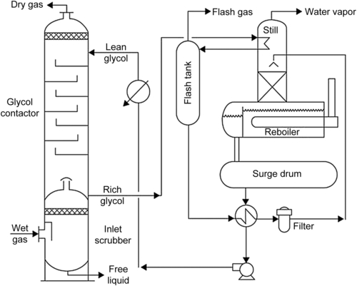
Basically, the liquid desiccant process is a two-step process. In the first step, the water is absorbed from the gas in a staged tower. The solvent is regenerated in a second column. The solvent is then returned to the first column to remove water from more feed gas. A simplified flow sheet for the glycol dehydration process is shown in Fig. 6.1.
The TEG natural gas dehydration unit operates at relatively high pressure on the contactor side and low pressure on the regeneration side. The high-pressure side comprises the glycol contactor and the inlet separator. The low-pressure side is made up of the regenerator and the flash tank and associated equipment.
The rest of this section discusses the individual components of the dehydration process in some detail.
6.2.2.1. Inlet Separator
The first step in the dehydration of natural gas is to remove any free liquids in the stream. A separator should be included upstream of the contactor to separate any hydrocarbon liquids and/or free water.
This separator could be a two- or three-phase separator, depending on the amount of free water expected. The inlet separator can be freestanding with interconnecting piping to the contactor or it can be as an integral part of the contactor, usually at the base of the contactor with a chimney tray between the contactor bottom and the separator vessel.
The separator should be equipped with a high-efficiency wire mesh mist extractor in the top portion to remove any liquid entrainment and particulates from the gas stream before entering the absorber section. Integral separators are usually outfitted with a heating coil to prevent water from freezing. Hot solvent from the accumulator is circulated through this heating coil to provide the required heat.
6.2.2.2. The Contactor
The contactor (also called an absorber) is the workhorse of the dehydration unit. It is in the contactor that the gas and liquid are mixed and the actual water removal takes place.
The contactor is a typical absorber tower properly sized with the process objective in mind. The feed gas flow rate is the most significant factor in determining the diameter of the contactor. The outlet gas water content specification is the key to determine the contactor height, although other factors contribute as well. The contactor is made up of a number of equilibrium stages, enough to ensure mass transfer from the gas phase to the liquid is such that the outlet gas is at the desired water specification. The actual stages could be either (1) trays like bubble caps, valve trays, or sieve trays or (2) a suitable packing material. Structured packing is finding more acceptance in glycol contactors.
The contactor operates by the fundamental principles of an absorber. The flow of streams is countercurrent. Feed gas enters the bottom of the contactor and flows upward. Lean solvent enters the top of the contactor and flows downwards. The solvent absorbs water as it travels downward through the column and the gas transfers the water to the solvent as it travels upward.
The contactor pressure is set by the feed gas pressure, which is normally in the range of 4000–8500 kPa (600–1200 psia). The contactor is essentially isothermal; that is, the temperature profile is essentially uniform throughout the contactor.
6.2.2.3. The Flash Tank
The rich glycol is withdrawn from the bottom of the contactor, usually on level control. Typically the lean glycol is preheated, often by passing it through tubes in the overhead condenser at the top of the still column. Then it is flashed at low pressure in a flash tank where most of the volatile components (entrained and soluble) are vaporized. Flash tank pressures are typically in the range of 300–700 kPa (50–100 psia).
The glycol leaves the flash tank, again usually on level control, and then passes through a filter. Then the rich glycol enters the rich–lean heat exchanger.
6.2.2.4. Lean–Rich Exchanger
The basic purpose of the lean–rich exchanger is to conserve energy. In the lean–rich exchanger, hot, lean glycol from the regeneration is cooled with rich from the contactor. The lean glycol entering the contactor should be cool and the rich glycol to regeneration should be warm.
6.2.2.5. The Regenerator
A basic regeneration unit is made up of a combination of a fired reboiler, located at the lower section of a horizontal vessel with a vapor space above the tube bundle, a distillation column (still column) connected vertically to the vapor space of the reboiler vessel, and a surge tank located below the reboiler. Also included in the regeneration unit is a condensing coil added to the top of the still column to provide reflux to improve solvent/water separation. As was noted previously, often this coil performs the dual purpose of preheating the rich glycol ahead of the flash tank.
The size of the regenerator is determined by a balance between the solvent circulation rate, the amount of water vapor in the gas stream, and the reboiler temperature. The standard TEG dehydration unit operates effectively at a reboiler temperature around 175 °C (350 °F), or about 20 °C (30 °F) below the decomposition temperature of TEG.
In the regenerator, the separation of water from glycol takes place by fractionation. Water and glycol have widely varying boiling points 100 °C (212 °F) for water vs 288 °C (549 °F) for TEG. Furthermore, the two substances can be easily separated by fractional distillation. This is accomplished in the still column mounted directly on top of the reconcentration vessel. Within the column water, rich vapor rises in intimate contact with descending glycol-rich liquid. Between the two phases, there is a continuous exchange of material and heat. The temperature difference causes the glycol vapor (heavy component) to condense and liquid water (light component) to vaporize. At the top of the column, the vapor is virtually pure water, whereas there is very little water in the glycol in the bottom. A small portion of the vapor mixture (mainly water) at the top condenses at the overhead condenser to provide sufficient reflux that will aid in the process of fractionation. The main purpose of the still column is to effect final separation between the absorbed water and the absorbing TEG glycol, to vent the separated water to the atmosphere, and to recover the glycol vaporized by the reboiler.
The glycol-rich liquid, now becoming lean glycol, leaves the bottom of the packed still column and enters the reboiler vessel. Heat is applied in the reboiler, which is usually direct fired, to raise the temperature and cause partial vaporization. In a normal TEG dehydration unit, this temperature level has been found to cause no noticeable thermal decomposition of the TEG. The lean hot glycol leaves the reboiler vessel and overflows by gravity to the surge tank, a vessel normally located below the reboiler vessel.
The hot, lean glycol passes to the lean–rich exchanger where it is cooled. Ultimately it is returned to the contactor and the cycle is complete.
6.2.2.6. Glycol Pump
A circulation pump takes suction from the surge tank and raises the pressure of the concentrated glycol and delivers the glycol to the top tray of the glycol contactor. It is via the pump that the glycol circulation rate is established.
From the pump discharge, the glycol is passed through the lean–rich exchanger to experience some cooling and then through the lean gas exchanger to experience further cooling before entering the contactor.
6.2.3. Short Cut Design Method
The description of the process presented earlier in this chapter gives many of the process parameters. However, several parameters were not discussed and are reviewed in this section.
In this section, some methods are presented for the preliminary sizing of a TEG dehydration unit. Those interested in a more detailed design procedure are referred to the paper by Sivalls (1976).
The most important parameter in the design of a glycol dehydration unit is the glycol circulation rate. In general, the lower the circulation rate the lower the operating cost for the glycol dehydration unit. The circulation rate for the rich glycol is typically between 17 and 33 L of glycol per kilogram of water in the inlet gas (2–4 gal/lb of water). Circulation rates less than 17 L/kg (2 gal/lb) are not recommended.
Given the water content of the inlet gas and the specified circulation rate per mass of water removed allows for the calculation of the actual circulation rate.
![]() (6.1)
(6.1)
A consistent set of units must be applied. For example, the circulation rate, L, will be in L/min if LW is in L/kg, wi is in kg/1000 Sm3 (or g/Sm3), and G is in 103 Sm3/day. Alternatively, using American Engineering units: L will be in gpm if LW is in gal/lb, wi is in lb/MMCF, and G is in MMCFD.
Typically, the gas enters the dehydration unit saturated with water, although this is not always the case. Methods for calculating the water content of gas are presented in Chapter 10. The water content of the outlet gas is the design specification.
The amount of water removed can be calculated using the following expression:
![]() (6.2)
(6.2)
where WR is the amount of water removed, wi is the water content of the inlet gas, wo is the water content of the exit gas, and G is the gas flow rate. As with the previous equation, Eqn (6.2) requires a consistent set of units.
The diameter of the contactor can be approximated using Fig. 6.2. This figure is only presented in American Engineering units. Even in countries where the metric system is commonly used, it is still typical to specify the column diameter in feet. Furthermore, it is common to round the approximate diameter to the nearest half-foot (6 in).
The duty for the regenerator reboiler can be estimated using the following equations:
![]() (6.3a)
(6.3a)
where Q is the duty in kJ/h and L is the circulation rate, in L/min, calculated as specified previously. Or in American Engineering units:
![]() (6.3b)
(6.3b)
where Q is the duty in Btu/h and L is the circulation rate, gpm.
In addition to absorbing water vapor, some hydrocarbons are also absorbed. As an approximate rule of thumb, TEG typically absorbs about 0.007 m3/L (1 SCF of sweet gas per gallon of glycol) at 7 MPa (1000 psia) and 38 °C (100 °F). The solubility will be significantly higher if the gas contains H2S and CO2.

This should give the reader sufficient information to perform preliminary sizing calculations for a TEG dehydration unit.
6.2.3.1. Benzene, Ethylbenzene, Toluene, and Xylenes
The solubility of paraffin hydrocarbons in TEG is very low. On the other hand, aromatic hydrocarbons (benzene, ethylbenzene, toluene, and xylenes, which are also called BTEX) have a significant solubility. About 25% of the aromatics in the gas stream could be absorbed by TEG under typical contactor conditions of temperature, pressure, and circulation rate. Aromatics absorption is higher for xylenes and lower for benzene. Aromatics absorption is a function of concentration in the gas steam, temperature and pressure of the contactor, and TEG circulation rate. The lower the circulation, the less is the absorption.
The absorption of aromatics by the desiccant and the subsequent liberation of these compounds during the regeneration step is a significant problem with the TEG dehydration process. The aromatic compounds are carcinogenic and therefore pose a health risk to those exposed to them.
6.2.3.2. Software
Process simulation has become very popular in the past few years. Powerful process simulation packages are available that easily fit onto the desktop computer of almost all design engineers.
The modern process simulation packages (Hysys, Aspen, SimSci, Prosim, and others) can be used to model glycol dehydration in all of its configurations. They can also be used for dehydration in a refrigeration process.
In addition, the Gas Research Institute sponsored a project to build a simulator specifically for glycol dehydration units. The resulting simulator is GRI Glycalc.
The design engineer should use these models with some caution. It was mentioned previously that hydrocarbon + methanol systems are difficult to model, and the same is true for glycol + hydrocarbon systems. When simulating these processes, the engineer should select a model suitable for these systems.
6.2.4. Approximate Capital Cost
Figure 6.3 is provided to make quick estimates (±30%) for the purchased cost of a glycol dehydration unit. These are based on information from the literature (Tannehill et al., 1994) and from the author's experience.

For both the dehydration units and the line heater, as an order of magnitude estimate, it can be assumed that the installation cost is between 0.8 and 1.2 times the purchased cost. In other words, the installation cost is approximately equal to the purchased cost.
Clearly these costs are approximate at best. Many factors have not been included, such as the operating pressure, TEG circulation rate, stripping gas, or no stripping gas, and so on. They should be used for rapid budget cost estimates only.
6.3. Mole Sieves
Unlike glycol dehydration, which is an absorption process, dehydration with molecular sieves is an adsorption process. Water in the gas adheres to the solid phase, the solid being the mole sieve and thus is removed from the natural gas. Molecular sieves are usually used when very dry gas is required (such as a cryogenic process). The mole sieve process can dry a gas to less than 1 ppm (1 mg/Sm3 or 0.05 lb/MMCF).
In the mole sieve process, the wet gas enters a bed of adsorbent material. The water in the gas adsorbs onto the bed and a dry gas is produced. Once the bed becomes saturated with water, that is, when no more water can be adsorbed, the bed must be regenerated.
Often, to reduce the size of the mole sieve unit, a glycol dehydration unit is used for bulk water removal. This is followed by a mole sieve unit for the final drying.
6.3.1. Process Description
The adsorption of water vapor from a gas stream is a semibatch process; therefore, at least two beds are required. One bed is in the adsorption phase and the other is in the regeneration or cooling phase. As the bed adsorbs water it becomes saturated, and that portion of the bed can no longer adsorb water. Once the entire bed is saturated with water, the bed must be regenerated.
Regeneration is achieved via the application of heat. Thus a hot gas stream is passed through the bed to strip the water and thus regenerate the bed. Following the stripping stage, the bed must be cooled before it can be placed back in service.
A simplified flow sheet for a two-bed adsorption scheme is shown in Fig. 6.4.

6.3.2. Simplified Modeling
Mole sieves are more difficult to model and usually require specialized software. One reason that mole sieves are more difficult to simulate is that they are semibatch operations. Typical process simulators are steady state and cannot properly handle the batch mode.
However, the adsorption takes place in a packed bed and the usual methods for sizing packed beds are applicable. The reader should consult Trent (2001) for guidelines for designing mole sieves.
Presented in this chapter are some rules of thumb for performing preliminary design calculations for molecular sieve dehydration. For dehydration of natural gas, the most commonly used mole sieve is Type 4A, which comes in either granular or spherical pellets. A summary of the properties of Type 4A is listed in Table 6.1.
The first consideration in the design of a mole sieve unit is to determine the amount of water to be adsorbed. This is calculated using Eqn (6.2).
Next the amount of mole sieve required can be estimated. It is typical to use an adsorption cycle of between 8 and 24 h, with 8 being typical. For design purposes with the Type 4A mole sieve, it is common to use an adsorption of 1 kg of water per 10 kg of adsorbent (1 lb water/10 lb mole sieve). This results in the mass of adsorbent required in the bed. The mass of adsorbent can then be converted to a volume with the bulk density of the adsorbent.
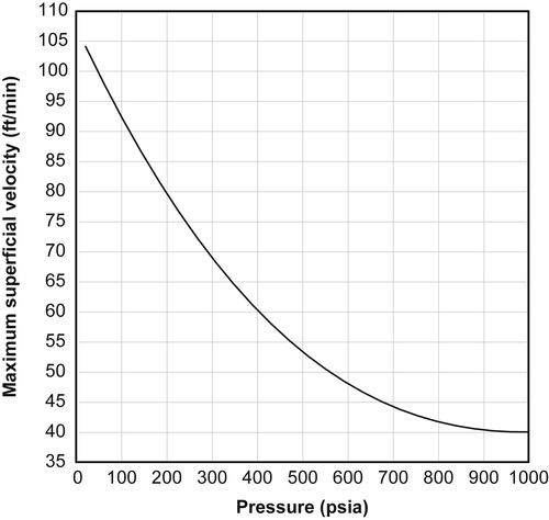
The next consideration is the velocity through the bed. When dealing with packed beds, it is usual to refer to the superficial velocity rather than the actual velocity. The actual velocity through the bed is a complex function of bed geometry and is a very difficult parameter to deal with. On the other hand, the superficial velocity is a synthetic number but it is readily calculated.
The maximum superficial velocity is a function of the total pressure. Figures 6.5 and 6.6 show the relationship between these two parameters, the first in SI units and the second in American Engineering units. If the velocity is greater than this value, the bed will not function properly.

Next, the pressure drop through the bed must be estimated. Because the beds are uniform and usually spherical, the pressure drop per unit length through the bed can be estimated using the Ergun equation:
 (6.4)
(6.4)
where ΔP is the pressure drop across the bed, L is the bed length, ρ is the gas density at process conditions, vs is the superficial velocity, ε is the void fraction of the bed, Dp is the particle diameter, and μ is the gas viscosity at process conditions.
It is typical to simplify this equation to the following relation
![]() (6.5)
(6.5)
where the parameters A and B are given in Table 6.2 for mole sieve materials. The units for the coefficients in Table 6.2 are ΔP/L in psia/ft, μ in centipoise, vs in ft/min, and ρ in lb/ft3. An important observation from this equation is that the higher the superficial velocity, the greater the pressure drop across the bed.
The design velocity is a tradeoff between the maximum velocity and the acceptable pressure drop. Typically, the pressure drop through the bed should be less than 35 kPa (5 psia), although in some cases it may be as high as 55 kPa (8 psia).
After the superficial velocity is determined, then the diameter of the bed, d, can be calculated using the following equation:
 (6.6)
(6.6)
where d is in m, Gact is the actual volumetric flow rate in m3/min, π is 3.14159…, and vs is the superficial velocity through the bed in m/min. This equation can also be used with American Engineering units if appropriate substitutions are made. The flow rate in the gas business is usually given in at standard conditions and these must be converted to the actual flow through the bed using the gas laws.
Table 6.2
Coefficients for Eqn (6.5)
| A | B | |
| 1/8-in beads | 0.0560 | 8.89 × 10⁻⁵ |
| 1/8-in extruded | 0.0722 | 1.24 × 10⁻⁴ |
| 1/16-in beads | 0.152 | 1.36 × 10⁻⁴ |
| 1/16-in extruded | 0.238 | 2.10 × 10⁻⁴ |
From the GPSA Engineering Data Book.
 (6.7)
(6.7)
where z is the compressibility factor of the gas at T and P, T is the process temperature expressed as an absolute temperature, Tstd is the standard temperature, again expressed as absolute temperature (usually 520 R or 288.7 K), Pstd is the standard pressure (usually 14.7 psia, 101.3 kPa or 1 atm), P is the process pressure, and Gstd is the gas volumetric flow rate at standard conditions. The design engineer should be able to calculate the compressibility factor and thus this is not discussed further at this point.
Next, given the diameter of the bed and the volume of material required, the height can be calculated from simple geometry.
6.4. Refrigeration
Another method for dehydrating natural gas is to use refrigeration. That is, to cool the gas. As will be demonstrated in a subsequent chapter, cool gas holds less water than hot gas.
The usual purpose of a refrigeration plant is to remove heavy hydrocarbons from a natural gas stream to make hydrocarbon dew point specification. But this process also removes water. The cold temperatures in a refrigeration process result in water removal because the cold gas can carry less water than warm. To prevent the formation of ice and hydrates, the cold gas is mixed with a polar solvent, usually EG. A typical refrigeration process can easily reduce the water content of a gas stream down to the 1 lb/MMCF level.
6.4.1. Process Description
A simplified flow sheet for the refrigeration process is shown in Fig. 6.7.
Gas enters a gas–gas exchanger, where it is precooled. Further cooling is achieved via refrigeration. The gas enters the reboiler of a refrigeration unit (it is the refrigerant that is boiled and the process steam that is cooled), called a “chiller.”
To prevent freezing (ice and/or hydrates) and to pick up condensing water, a glycol is sprayed into both the gas–gas exchanger and the chiller. The glycol of choice for this application is EG because it has better low temperature properties than other glycols.

The mixture enters a low-temperature separator (LTS) where the gas comes off the top, liquid hydrocarbon comes out the middle, and a mixture of glycol and water come out the bottom (usually a boot). The hydrocarbon liquids are sent for further treating. The glycol–water mixture is sent to a regeneration still where the glycol is regenerated for reuse.
The sales gas, the gas off the top of the LTS, is very cold. Therefore it is sent back through the gas–gas exchanger to precool the feed gas and recover some of its energy.
With propane as the refrigerant, which is typical in the natural gas industry, the chiller temperature is usually in the range −10 to −40 °C (+15 to −40 °F).
One big advantage of this type of process is that it can produce a gas that meets both the hydrocarbon dew point and water content specifications. There is no need for separate a dehydration unit and a hydrocarbon dew-point control.
6.4.2. Glycol Injection
Ironically, the glycol injection rate and the concentration of the glycol are usually not dictated by the hydrate considerations discussed previously. The physical properties of the solution play a more important role in this design.
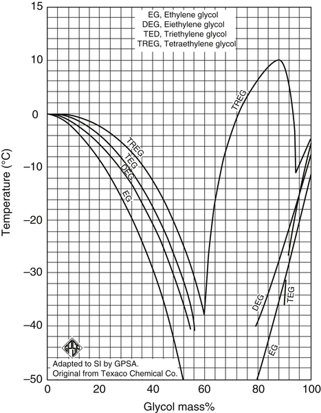
EG and water have a eutectic at approximately 80 wt% EG. A eutectic is approximately equivalent to an azeotrope in the boiling point. Mixtures of EG + water freeze at lower temperatures than the pure components. The freezing points of EG + water mixtures are shown in Figs 6.8 and 6.9. Freezing points of other glycol + water mixtures are also shown on these plots.
The minimum injection rate is about 2 L/min (0.5 gpm) because of mechanical and contact considerations. Injection rates less than this do not achieve the desired distribution in the exchangers.

Beyond the mechanical limits, typically the glycol is injected at 80 wt% and the minimum withdraw concentration is usually about 70 wt%.
Examples
Example 6.1
A wet natural gas stream is to be dehydrated using a TEG dehydration unit. The flow rate of the gas is 10 MMCF (283 × 103 Sm3/day) and it is at 120 °F (48.9 °C) and 600 psia (4137 kPa). At these conditions, the gas is saturated with water, 150 lb/MMCF (2400 mg/Sm3).
The gas is to be dried to 7 lb/MMCF (112 mg/Sm3). Calculate the circulation rate, the diameter of the contactor, and the reboiler duty. Use a glycol rate of 2.5 gal of glycol per lb of water (0.3 kg/L).
Answer: From Eqn (6.1), the circulation rate can be calculated:
![]()
This converts to 590 L/min.
The contactor diameter can be estimated from Fig. 6.2. From that figure, the diameter is slightly more than 24 inches (61 cm).
Finally, the reboiler duty can be estimated from Eqn (6.3a):
![]()
this converts to 329,000 kJ/h.
Example 6.2
Estimate the capital cost for a TEG dehydration unit (sweet service) for a gas flow rate of 10 MMCFD flow.
Answer: From the chart this is slightly less than $100,000 (US). Reading the chart more closely reveals that the value is closer to $125,000 (US).
Example 6.3
Perform the sizing calculation for the mole sieve bed for dehydrating the gas in Example 6.1 to 1 ppm. The properties of the gas at 120 °F and 600 psia are as follows: density: 2.2 lb/ft3, viscosity: 0.01 cp, z-factor: 0.90. This example will be done using only American Engineering units. The reader is invited to repeat the calculation using SI units.
Answer: The total water adsorbed is 150 × 10 = 1500 lb/day. Assuming a 12 h cycle, this means 750 lb of water are adsorbed per cycle. This requires 7500 lb of mole sieve. Given that the bulk density of the mole sieve is 42 lb/ft3 means that 178.6 ft3 of mole sieve in the bed.
Next convert the standard flow rate into an actual flow rate.

From Fig. 6.6, the maximum allowable superficial velocity through the bed is 48 ft/min. Use this value as a starting point. Calculated the pressure drop per unit length:

Next calculate the bed diameter:

Calculate the height of the bed from simple geometry:

And finally the total pressure drop
![]()
This pressure drop is unacceptably large. Reduce the superficial velocity to 40 ft/min and repeat the calculation.


![]()
This pressure drop is still a little large, so further reduce the velocity to 35 ft/min and once again repeat the procedure.


![]()
This value is still marginally too large, but the procedure is well-established.
..................Content has been hidden....................
You can't read the all page of ebook, please click here login for view all page.