
4. A Tour of Some Component-and-Connector Styles

4.1 An Introduction to C&C Styles
A component-and-connector (C&C) style introduces a specific set of component-and-connector types and specifies rules about how elements of those types can be combined. Additionally, given that C&C views capture runtime aspects of a system, a C&C style is typically also associated with a computational model that prescribes how data and control flow through systems designed in that style.
The choice of a C&C style (or styles) will usually depend on the nature of the runtime structures in the system. For example, if the system will need to access a set of legacy databases, the style will likely be based on a shared-data style. Alternatively, if a system is intended to perform data stream transformation, a data flow style will likely be chosen.
![]()
In Section 4.9 we provide references for reading about dozens of C&C styles.
The choice of style will also depend on the intended use of the documentation. For example, if high performance is a critical property, the style will likely be chosen to enable analysis of performance, so that trade-offs affecting that system quality can be assessed.
Many C&C styles exist. To make sense of the space of these styles, we begin by describing some broad categories of commonly used C&C styles, and then we consider in more detail one or more example styles in each category.
The space of C&C styles is quite large. For example, C&C styles can differ dramatically in terms of the types of the connectors that they support. Styles based on asynchronous event broadcast (such as publish-subscribe) are quite different from those based on synchronous service invocation. Similarly, styles may differ in terms of the types of components that they permit or require. For instance, some styles require a database component to be present. Other styles may require a registry component to enable components to find others at runtime. Styles may differ in terms of topological restrictions, such as whether the components are assigned to tiers. They may also differ in terms of their level of domain specificity. For example, a style to support automotive control systems will likely involve connectors that represent specific protocols for real-time coordination. Similarly, there exist dozens of client-server styles that differ in subtle (or not-so-subtle) ways, depending on the nature of the application domain they are addressing. For example, some client-server styles allow late binding of requests for services, where the recipient of a request is determined dynamically; others insist on a static configuration determined when a system is built or deployed.
![]()
Section 6.1.4 discusses how styles can be progressively specialized from generic styles to domain-specific styles and product line.
One way to impose some conceptual order on the space of C&C styles is to consider several broad categories of styles, differentiated primarily by their underlying computational model. In this chapter we consider examples in four such categories.
• Call-return styles. Styles in which components interact through synchronous invocation of capabilities provided by other components.
• Data flow styles. Styles in which computation is driven by the flow of data through the system.
• Event-based styles. Styles in which components interact through asynchronous events or messages.
• Repository styles. Styles in which components interact through large collections of persistent, shared data.
Additionally we consider several crosscutting style issues, such as the imposition of a tiered topology, and augmentations that allow one to reason about concurrency.
![]()
Section 4.6.1 describes communicating processes, which is a way to add concurrency to a C&C style. Section 4.6.2 describes the notion of tiers, which are common in some C&C architectures.
Figure 4.1 provides a birds-eye view of part of the terrain. This figure can be interpreted as a kind of C&C style specialization hierarchy. At the top is the most general and unconstrained form of C&C view: namely, one that uses generic components and connectors, with no particular constraints on topology, behavior, and element properties. Below this are the general categories of C&C styles distinguished largely by their underlying computational model. Below these are specializations of these general styles. Note that a specific style may specialize more than one general category, as is the case of the service-oriented architecture (SOA) style.
Figure 4.1 A partial representation of the space of C&C styles

Naturally this is only a partial representation of the space of C&C styles: there are other general categories, and there are many styles that are specializations of these categories. Additionally, in most real systems several styles may be used together, often from across categories. For example, enterprise IT applications are frequently a combination of client-server and shared-data styles.
![]()
See Section 6.6 for a discussion of documenting a view that combines more than one style.
4.2 Data Flow Styles
Data flow styles embody a computational model in which components act as data transformers and connectors transmit data from the outputs of one component to the inputs of another. Each component type in a data flow style has some number of input ports and output ports. Its job is to consume data on its input ports and write transformed data to its output ports.
A variety of data flow styles appear in practice. In the early days of computing, one common data flow style was “batch sequential,” a style in which each component transforms all of its data before the next component can consume its outputs. Later a form of data flow style was invented in which components run concurrently and data is incrementally processed: the pipe-and-filter style. Today data flow styles are common in domains where stream processing occurs, and where the overall computation can be broken down into a set of transformational steps.
4.2.1 Pipe-and-Filter Style
Overview
The pattern of interaction in the pipe-and-filter style is characterized by successive transformations of streams of data. Data arrives at a filter’s input ports, is transformed, and then is passed via its output ports through a pipe to the next filter. A single filter can consume from, or produce data to, multiple ports. Modern examples of such systems are signal-processing systems, systems built using UNIX pipes, the request-processing architecture of the Apache Web server, the map-reduce paradigm for search engines, Yahoo! Pipes for processing RSS feeds, and many scientific computation systems that have to process and analyze large streams of experimental data.
Elements, Relations, and Properties
The basic form of pipe-and-filter style, summarized in Table 4.1, provides a single type of component—the filter—and a single type of connector—the pipe. A filter transforms data that it receives through one or more pipes and transmits the result through one or more pipes. Filters typically execute concurrently and incrementally. A pipe is a connector that conveys streams of data from the output port of one filter to the input port of another filter. Pipes act as unidirectional conduits, providing an order-preserving, buffered communication channel to transmit data generated by filters. In the pure pipe-and-filter style, filters interact only through pipes.
Table 4.1 Summary of the pipe-and-filter style

Because pipes buffer data during communication, filters can act asynchronously and concurrently. Moreover, a filter need not know the identity of its upstream or downstream filters. For this reason, pipe-and-filter systems have the nice formal property that the overall computation can be treated as the functional composition of the computations of the filters, allowing the architect to reason about the end-to-end behavior as a simple composition of the behaviors of the parts.
What the Pipe-and-Filter Style Is For
Systems conforming to a pipe-and-filter style are typically used in data transformation systems, where the overall processing can be broken down into a set of independent steps, each responsible for an incremental transformation of its input data. The independence of the processing done by each step supports reuse, parallelization, and simplified reasoning about overall behavior.
Often such systems constitute the front end of signal-processing applications. These systems typically receive sensor data at a set of initial filters; each of these filters compresses the data and performs initial filtering. “Downstream” filters reduce the data further and do synthesis across data derived from different sensors. The final filter typically passes its data to an application, for example, providing input to modeling or visualization tools.
Analyses associated with pipe-and-filter systems include deriving the aggregate transformation provided by a graph of filters and reasoning about system performance: input/output stream latency, pipe buffer requirements, and throughput.
Relation to Other Styles and Models
A pipe-and-filter view of a system is not the same as a data flow model. In the pipe-and-filter style, lines between components represent connectors, which have a specific computational meaning: They transmit streams of data from one filter to another. In data flow models, the lines represent relations, indicating the communication of data between components. Flows in a data flow model have little computational meaning: They simply indicate that data flows from one element to the next. This flow might be realized by a connector, such as a procedure call, the routing of an event between a publisher and a subscriber, or data transmitted via a pipe. The reason that these views might be confused is that the data flow model of a pipe-and-filter style looks almost identical to the original pipe-and-filter view.
![]()
Data flow models are discussed in “Perspectives: Data Flow and Control Flow Models,” on page 146, in Chapter 3.
Data flow styles are often combined with other styles by using them to characterize a particular subsystem. A good example of this is the filter processing chains of the Apache Web server.
Example of the Pipe-and-Filter Style: Yahoo! Pipes
“Rewire the Web” is the motto of Yahoo! Pipes, a composition tool that lets Web users combine simple functions quickly and easily into pipe-and-filter applications that aggregate and manipulate content from around the Web.
The basis of Yahoo! Pipes is the many RSS feeds available from sites on the Internet. These data streams form the input to the applications that users build, applications that combine and manipulate the data in the streams to form useful results. Many of the building blocks to perform general-purpose filtering and manipulation of the data streams are made available in the composition environment itself, rather like library functions.
For example, you can take an RSS stream from a financial news site and filter it so that only news items related to stocks that you own are shown. Or you can take an RSS stream from a sports site and filter it so that you see news about your favorite teams or athletes.
Yahoo! Pipes uses terminology not quite the same as that in this book. It calls a complete application a pipe; the building blocks are called modules. A filter is a special kind of module that removes values from a stream based on given comparison criteria.
Figure 4.2 shows an application that finds an apartment for rent that is near a given type of business, such as a movie theater. This is based on one of the teaching examples on the Yahoo! Pipes Web site.
Figure 4.2 A Yahoo! Pipes application for finding apartments for rent near a given location (shown using the notation of the Yahoo! Pipes editor). The pipe-and-filter flow runs from top to bottom through the seven “modules” down the left-hand side (each representing what our pipe-and-filter style calls a filter); this is indicated by the thick solid lines (the pipes) connecting the output port of one to the input port of the next. The other “modules” supply inputs to the mainline components; this is indicated by the thinner, hollow lines. The Fetch Feed component uses the RSS output from an apartment-finder search; it is fed the search site URL and the search parameters by the helper modules to its right. The Location Extractor and the Filter component extract high-quality (well-formed) addresses from the apartment-finder search. That stream feeds Yahoo! Local, which finds businesses of a given type (supplied by its helper module) near a given location. (The For Each component applies the function shown in its interior to every item in the input stream.) The second Filter removes listings that aren’t a minimum distance from our search term. The Sort component orders the stream in ascending order of distance for viewing via the Pipe Output component.

4.3 Call-Return Styles
Call-return styles embody a computational model in which components provide a set of services that may be invoked by other components.1 A component invoking a service pauses (or is blocked) until that service has completed. Hence, call-return is the architectural analog of a procedure call in programming languages. The connectors are responsible for conveying the service request from the requester to the provider and for returning any results.
Call-return styles differ among each other in a variety of ways. Some variants differ in terms of the behavior of their connectors. For example, connectors in some call-return styles may support error handling (such as when the service provider is not available). Other differences relate to constraints on topology. Some call-return architectures are organized in tiers. Others partition the set of components into disjoint sets of components that can make requests and those that can service them.
![]()
The organization of components in tiers and multi-tier architectures are discussed in Section 4.6.2.
Examples of call-return styles include client-server, peer-to-peer, and representational state transfer (REST) styles.
![]()
Wikipedia provides a nice description of the REST architecture style, at en.wikipedia.org/wiki/REST (Wikipedia 2010b).
4.3.1 Client-Server Style
Overview
As with all call-return styles, client-server style components interact by requesting services of other components. Requesters are termed clients, and service providers are termed servers, which provide a set of services through one or more of their ports. Some components may act as both clients and servers. There may be one central server or multiple distributed ones.
Typical examples of systems in the client-server style include the following:
• Information systems running on local networks, where the clients are GUI applications (such as Visual Basic) and the server is a database management system (such as Oracle)
• Web-based applications where the clients run on Web browsers and the servers are components running on a Web server (such as Tomcat)
Elements, Relations, and Properties
In the client-server style, summarized in Table 4.2, component types are clients and servers. The principal connector type for the client-server style is the request/reply connector used for invoking services. When more than one service can be requested on the same connector, a protocol specification is often used to document ordering relations among the invocable services over that connector. Servers have ports that describe the services they provide. Clients have ports that describe the services they require. Servers may in turn act as clients by requesting services from other servers. A component that has both service-request and service-reply ports can function as both a client and a server simultaneously.
Table 4.2 Summary of the client-server style

![]()
A protocol of interactions can be described using notations such as sequence diagrams and state diagrams, which are covered in Chapter 8.
The computational flow of pure client-server systems is asymmetric: clients initiate interactions by invoking services of servers. Thus, the client must know the identity of a service to invoke it, and clients initiate all interaction. In contrast, servers do not know the identity of clients in advance of a service request and must respond to the initiated client requests.
Service invocation is synchronous: the requester of a service waits, or is blocked, until a requested service completes its actions, possibly providing a return result. Variants of the client-server style may introduce other connector types. For example, in some client-server styles, servers are permitted to initiate certain actions on their clients. This might be done by allowing a client to register notification procedures, or callbacks, that the server calls at specific times. In other systems service calls over a request/reply connector are bracketed by a “session” that delineates the start and end of a set of client-server interactions.
What the Client-Server Style Is For
The client-server style presents a system view that separates client applications from the services they use. This style supports system understanding and reuse by factoring out common services. Because servers can be accessed by any number of clients, it is relatively easy to add new clients to a system. Similarly, servers may be replicated to support scalability or availability.
Relation to Other Styles
Like many C&C styles, the client-server style decouples producers of services and data from consumers of those services and data. Other styles, such as peer-to-peer, involve a round-trip form of communication. However, these styles do not have the asymmetric relationship between clients and servers found in the client-server style.
Clients and servers are often grouped and deployed on different machines in a distributed environment to form a multitier hierarchy.
Examples of the Client-Server Style
The World Wide Web may be the best known example of a system that is, at its heart, a client-server system. It is a hypertext-based system that allows clients (Web browsers) to access information from servers distributed across the Internet. Clients access the information, written in Hypertext Markup Language (HTML), provided by a Web server using Hypertext Transfer Protocol (HTTP). HTTP is a form of request/reply invocation. HTTP is a stateless protocol; the connection between the client and the server is terminated after each response from the server.
For another example, Figure 4.3 uses informal notation to describe the client-server view of an ATM banking system developed in the early 1990s. At that time, client-server architectures were the modern alternative to mainframe-based systems. (J2EE and .NET application servers didn’t exist and multi-tier was not yet described as a style.)
Figure 4.3 Client-server architecture of an ATM banking system. The ATM main process sends requests to Bank transaction authorizer corresponding to user operations (such as deposit, withdrawal). It also sends messages to ATM monitoring server informing the overall status of the ATM (devices, sensors, and supplies). The Reconfigure and update process component sends requests to ATM reconfiguration server to find out if a reconfiguration command was issued for that particular ATM. Reconfiguration of an ATM (for example, enabling or disabling a menu option) and data updates are issued by bank personnel using the Monitoring station program. Monitoring station program also sends periodic requests to ATM monitoring server to retrieve the status of the range of ATMs monitored by that station.

In this architecture, there are three types of components:
• The FTX server daemons are processes running in the background on the fault-tolerant UNIX (FTX) server. Each daemon creates one or more socket ports using predefined TCP ports, through which calls from client components arrive.
• ATM OS/2 client processes are concurrent processes that run on the ATMs, which were powered with the IBM OS/2 operating system. Although it can’t be inferred from the diagram, each ATM runs one instance of the ATM main process and one instance of the Reconfigure and update process.
• The Windows application component was also a client component. It was a Windows 3.x GUI program developed using the Borland OWL API. Each instance was used by an operator to monitor a group of ATMs from his or her workstation.
When this system was developed, the TCP socket connector was very often used for communication in client-server and distributed applications. Today HTTP is far more common. In the protocol used in this TCP socket connector, the client opens a connection to a server identified by an IP address and port number. The client then sends a nonblocking request, after which it may display in the UI a “Please wait...” message to the user. Then the client calls an operation to receive the response from the server. For both client and server, sending and receiving messages are separate steps. Therefore, the connector implementation has to handle the correlation of request and response messages, as well as time-outs and communication errors.
4.3.2 Peer-to-Peer Style
Overview
In the peer-to-peer style, components directly interact as peers by exchanging services. Peer-to-peer communication is a kind of request/reply interaction without the asymmetry found in the client-server style. That is, any component can, in principle, interact with any other component by requesting its services. Each peer component provides and consumes similar services, and sometimes all peers are instances of the same component type. Connectors in peer-to-peer systems may involve complex bidirectional protocols of interaction, reflecting the two-way communication that may exist between two or more peer-to-peer components.
![]()
The peer-to-peer architecture style has inspired new models for industrial production, community knowledge, political movement, property ownership, and an economic alternative to capitalism. See en.wikipedia.org/wiki/Peer-to-peer_(meme).
Examples of peer-to-peer systems include file-sharing networks, such as BitTorrent and eDonkey; instant messaging and VoIP applications, such as Skype; and desktop grid computing systems.
Elements, Relations, and Properties
Table 4.3 summarizes the peer-to-peer style. The component types in this style are peers, which are typically independent programs running on network nodes. The principal connector type is the call-return connector. Unlike in the client-server style, the interaction may be initiated by either party: each peer component acts as both client and server. Peers have interfaces that describe the services they request from other peers and the services they provide. The computational flow of peer-to-peer systems is symmetric: Peers first connect to the peer-to-peer network and then initiate actions to achieve their computation by cooperating with their peers by requesting services from one another.
Table 4.3 Summary of the peer-to-peer style

Often a peer’s search for another peer is propagated from one peer to its connected peers for a limited number of hops. A peer-to-peer architecture may have special peer nodes (called ultrapeers, ultranodes, or supernodes) that have indexing or routing capability and allow a regular peer’s search to reach a larger number of peers.
Constraints on the use of the peer-to-peer style might limit the number of peers that can be connected to a given peer or impose a restriction about which peers know about which other peers.
What the Peer-to-Peer Style Is For
Peers interact directly among themselves and can play the role of both service caller and service provider, assuming whatever role is needed for the task at hand. This partitioning provides flexibility for deploying the system across a highly distributed platform. Peers can be added and removed from the peer-to-peer network with no significant impact, resulting in great scalability for the whole system.
Typically multiple peers have overlapping capabilities, such as providing access to the same data. Thus, a peer acting as client can collaborate with multiple peers acting as servers to complete a certain task. If one of these multiple peers becomes unavailable, the others can still provide the services to complete the task. The result is improved overall availability. The load on any given peer component acting as a server is reduced, and the responsibilities that might have required more server capacity and infrastructure to support it are distributed. This can decrease the need for other communication for updating data and for central server storage, but at the expense of storing the data locally.
Peer-to-peer computing is often used in distributed computing applications, such as file sharing, instant messaging, and desktop grid computing. Using a suitable deployment, the application can make efficient use of CPU and disk resources by distributing computationally intensive work across a network of computers and by taking advantage of the local resources available to the clients. The results can be shared directly among participating peers.
Relation to Other Styles
The absence of hierarchy means that peer-to-peer systems have a more general topology than client-server systems.
Examples of the Peer-to-Peer Style
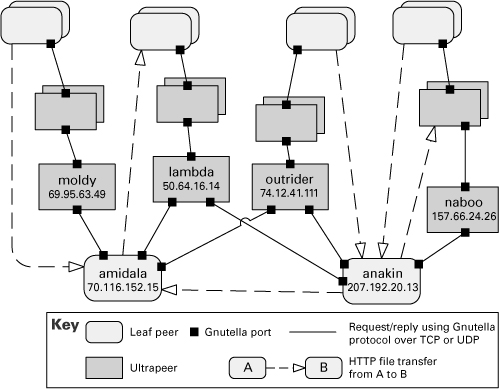
Gnutella is a peer-to-peer network that supports bidirectional file transfers. The topology of the system changes at runtime as peer components connect and disconnect to the network. A peer component is a running copy of a Gnutella client program connected to the Internet. Upon startup, this program establishes a connection with a few other peers. The Web addresses of these peers are kept in a local cache.
![]()
In late 2007, [Gnutella] was the most popular file sharing network on the Internet with an estimated market share of more than 40%.
—Wikipedia
(en.wikipedia.org/wiki/Gnutella)
The Gnutella protocol supports request/reply messages for peers to connect to other peers and search for files. Peers are identified by their IP address, and the Gnutella protocol messages are carried over dedicated UDP and TCP ports. To perform a search, a Gnutella peer requests information from all of its connected peers, which respond with any information of interest. The connected peers also pass the request to their peers successively, up to a predefined number of “hops.” All the peers that have positive results for the search request reply directly to the requester, whose IP address and port number go along with the request. The requester then establishes a connection directly with the peers that have the desired file and initiates the data transfer using HTTP (outside the Gnutella network).
Later versions of Gnutella differentiate between leaf peers and ultrapeers. An ultrapeer runs on a computer with a fast Internet connection. A leaf peer is usually connected to a small number (say, three) of ultrapeers, and an ultrapeer is connected to a large number of other ultrapeers and leaf peers. The ultrapeers are responsible for routing search requests and responses for all leaf peers connected to them.
Figure 4.4 shows part of a peer-to-peer view of a Gnutella network using an informal C&C notation. For brevity, only two leaf peers and four ultrapeers are identified. Each of the identified leaf peers uploads and downloads files directly from other peers.
Figure 4.4 A C&C diagram of a Gnutella network, using informal notation
![]()
Documentation of behavior is discussed in Chapter 8.
4.3.3 Service-Oriented Architecture Style
Overview
Service-oriented architectures consist of a collection of distributed components that provide and/or consume services. In SOA, service provider components and service consumer components can use different implementation languages and platforms. Services are largely standalone: service providers and service consumers are usually deployed independently, and often belong to different systems or even different organizations.
Elements, Relations, and Properties
Table 4.4 summarizes the SOA style. The basic component types in this style are service providers and service consumers, which in practice can take different forms, from JavaScript running on a Web browser to CICS transactions running on a mainframe.
Table 4.4 Summary of the service-oriented architecture style

In addition to the service provider and consumer components that you develop, your SOA application may use specialized components that act as intermediaries and provide infrastructure services:
• Service invocation can be mediated by an enterprise service bus (ESB). An ESB routes messages between service consumers and service providers. In addition, an ESB can convert messages from one protocol or technology to another, perform various data transformations (for example, format, content, splitting, merging), perform security checks, and manage transactions. When an ESB is in place, the architecture follows a hub-and-spoke design, and interoperability, security, and modifiability are improved. When an ESB is not in place, service providers and consumers communicate to each other in a direct point-to-point fashion.
![]()
Including an ESB in your architecture of a service-oriented system improves interoperability, security, and modifiability.
• To improve the transparency of location of service providers, a service registry can be used in SOA architectures. The registry is a component that allows services to be registered and then queried at runtime. It increases modifiability by making the location of the service provider transparent to consumers and permitting multiple live versions of the same service.
• An orchestration server (or orchestration engine) is a special component that executes scripts upon the occurrence of a specific event (for example, a purchase order request arrived). It orchestrates the interaction among various service consumers and providers in an SOA system. Applications with well-defined business workflows that involve interactions with distributed components or systems gain in modifiability, interoperability, and reliability by using an orchestration server. Many orchestration servers support the Business Process Execution Language (BPEL) standard.
![]()
There are many possibilities for communication between components in an SOA architecture, such as SOAP, REST, JMS, MSMQ, and SMTP. Try to indicate in your C&C diagram what protocol or technology is used for each component interaction by using labels or different arrow types.
The basic types of connectors used in SOA are these:
• Call-return connectors. Two of the most common such connectors are SOAP and REST:
– SOAP is the standard protocol for communication in Web services technology. Service consumers and providers interact by exchanging request/reply XML messages, typically on top of HTTP.
– With the REST connector, a service consumer sends synchronous HTTP requests. These requests rely on the four basic HTTP commands (post, get, put, and delete) to tell the service provider to create, retrieve, update, or delete a resource (a piece of data). Resources have a well-defined representation in XML, JSON, or a similar language/notation.
• Asynchronous messaging. Components exchange asynchronous messages, usually through a messaging system such as IBM WebSphere MQ, Microsoft MSMQ, or Apache ActiveMQ. The messaging connector can be point-to-point or publish-subscribe. Messaging communication typically offers great reliability and scalability.
Components have interfaces that describe the services they request from other components and the services they provide. Components initiate actions to achieve their computation by cooperating with their peers by requesting services from one another.
In practice, SOA environments may involve a mix of the three connectors listed above, along with legacy protocols and other communication alternatives (such as SMTP).
What Service-Oriented Architectures Are Good For
The main benefit and the major driver of SOA is interoperability. Because service providers and service consumers may run on different platforms, service-oriented architectures often integrate different systems and legacy systems. Service-oriented architecture also offers the necessary elements to interact with external services available over the Internet. Special SOA components such as the registry or the ESB also allow dynamic reconfiguration, which is useful when there’s a need to replace or add versions of components with no system interruption.
Example of a Service-Oriented Architecture
Figure 4.5 was taken from the example software architecture document accompanying this book online, at wiki.sei.cmu.edu/sad. It shows the SOA view of the Adventure Builder system (Adventure Builder 2010). This system interacts via SOAP Web services with several other external service providers. Note that the external providers can be mainframe systems, Java systems, or .NET systems—the nature of these external components is transparent because the SOAP connector provides the necessary interoperability.
Figure 4.5 Diagram of the SOA view for the Adventure Builder system. The OPC (Order Processing Center) component coordinates the interaction with internal and external service consumers and providers

4.4 Event-Based Styles
Event-based styles allow components to communicate through asynchronous messages. Such systems are often organized as a loosely coupled federation of components that trigger behavior in other components through events.
A variety of event styles exist. In some event styles, connectors are point-to-point, conveying messages in a way similar to call-return, but allowing more concurrency, because the event sender need not block while the event is processed by the receiver. In other event styles, connectors are multi-party, allowing an event to be sent to multiple components. Such systems are often called publish-subscribe systems, where the event announcer is viewed as publishing the event that is subscribed to by its receivers.
4.4.1 Publish-Subscribe Style
Overview
In the publish-subscribe style, summarized in Table 4.5, components interact via announced events. Components may subscribe to a set of events. It is the job of the publish-subscribe runtime infrastructure to make sure that each published event is delivered to all subscribers of that event. Thus the main form of connector in this style is a kind of event bus. Components place events on the bus by announcing them; the connector then delivers those events to the components that have registered an interest in those events.
Table 4.5 Summary of the publish-subscribe style

The computational model for the publish-subscribe style is best thought of as a system of independent processes or objects, which react to events generated by their environment, and which in turn cause reactions in other components as a side effect of their event announcements.
Examples of systems that employ the publish-subscribe style are the following:
• Graphical user interfaces, where a user’s low-level input actions are treated as events that are routed to appropriate input handlers
• Applications based on the model-view-controller (MVC) pattern, where view components are notified when the state of a model object changes
• Extensible programming environments, in which tools are coordinated through events
• Mailing lists, where a set of subscribers can register interest in specific topics
• Social networks, where “friends” are notified when changes occur to a person’s Web site
Elements, Relations, and Properties
The publish-subscribe style can take several forms. In one common form, called implicit invocation, the components have procedural interfaces, and a component registers for an event by associating one of its procedures with each subscribed type of event. When an event is announced, the associated procedures of the subscribed components are invoked in an order usually determined by the runtime infrastructure. Graphical user-interface frameworks, such as Visual Basic, are often driven by implicit invocation: User code fragments are associated with predefined events, such as mouse clicks.
In another publish-subscribe form, events are simply routed to the appropriate components. It is the component’s job to figure out how to handle the event. Such systems put more of a burden on individual components to manage event streams, but also permit a more heterogeneous mix of components than implicit invocation systems do.
In some publish-subscribe systems, an event announcer may block until an event has been fully processed by the system. For example, some user-interface frameworks require that all views be updated when the data they depict has been changed. This is accomplished by forcing the component that announces a “changed-data” event to block until all subscribing views have been notified.
What the Publish-Subscribe Style Is For
The publish-subscribe style is used to send events and messages to an unknown set of recipients. Because the set of event recipients is unknown to the event producer, the correctness of the producer cannot depend on those recipients. Thus new recipients can be added without modification to the producers.
Publish-subscribe styles are often used to decouple user interfaces from applications. They may also be used to integrate tools in a software development environment: tools interact by announcing events that trigger invocation of other tools. Other applications include systems such as bulletin boards, social networks, and message lists, where some dynamically changing set of users are notified when the content that they care about is modified.
Relation to Other Styles
The publish-subscribe style is similar to a blackboard repository style, because in both styles components are automatically triggered by changes to some component. However, in a blackboard system, the database is the only component that generates such events; in a publish-subscribe system, any component may generate events.
Implicit invocation is often combined with call-return in systems in which components may interact either synchronously by service invocation or asynchronously by announcing events. For example, many service-oriented architectures and distributed object systems (such as CORBA and Java EE) support both synchronous and asynchronous communication. In other object-based systems, synchronous procedure calls are used to achieve asynchronous interaction using the MVC pattern or the observer pattern.
Example of the Publish-Subscribe Style
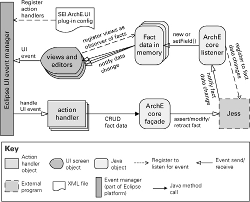
Figure 4.6 is a publish-subscribe view of the SEI ArchE tool. There are three different publish-subscribe interactions in this architecture:
1. Eclipse UI event manager acts as an event bus for user-interface events (such as button clicks). Subscription information—that is, what UI events are relevant to the system and what components handle them—is defined at load time when the event manager reads the SEI.ArchE.UI plug-in config XML file. From then on a UI event generated by the user working on a view or editor is dispatched via implicit invocation to the action handler objects that subscribe to that event.
![]()
Sections 2.3.6 and 6.6.4 have more information about the ArchE tool.
2. The data manipulated in ArchE is stored using a rule engine called Jess. Data elements are called facts. When a user action creates, updates, or deletes a fact, that action generates respectively an assert, modify, or retract fact event that is sent to Jess. When Jess processes that event, changes to many other facts may be triggered. Jess also acts as an event bus that announces changes to facts. In the ArchE architecture, there is one component that subscribes to all data changes: ArchE core listener.
3. ArchE keeps in memory copies of the fact data elements persisted in the rule engine. These copies are observable Java objects. User-interface screens (that is, views) that display those elements are observers of the fact data objects. When facts in memory are created or updated, the views are notified.
Figure 4.6 Diagram for a publish-subscribe view of the SEI ArchE tool
![]()
The observer design pattern is described in the book by Gamma et al. (1995).
4.5 Repository Styles
Repository views contain one or more components, called repositories, which typically retain large collections of persistent data. Other components read and write data to the repositories. In many cases access to a repository is mediated by software called a database management system (DBMS) that provides a call-return interface for data retrieval and manipulation. MySQL is an example of a DBMS. Typically a DBMS also provides numerous data management services, such as support for atomic transactions, security, concurrency control, and data integrity. In C&C architectures where a DBMS is used, a repository component often represents the combination of the DBMS program and the data repository.
Repository systems where the data accessors are responsible for initiating the interaction with the repository are said to follow the shared-data style. In other repository systems, the repository may take responsibility for notifying other components when data has changed in certain prescribed ways. These systems follow the blackboard style. Many database management systems support a triggering mechanism activated when data is added, removed, or changed. You can employ this feature to create an application following the blackboard style. But if your application uses the DBMS for retrieving and changing data in the repository but doesn’t employ triggers, you’re following the pure shared-data style.
4.5.1 Shared-Data Style
Overview
In the shared-data style, the pattern of interaction is dominated by the exchange of persistent data. The data has multiple accessors and at least one shared-data store for retaining persistent data.
Database management systems and knowledge-based systems are examples of this style.
Elements, Relations, and Properties
The shared-data style, summarized in Table 4.6, is organized around one or more shared-data stores, which store data that other components may read and write. Component types include shared-data stores and data accessors. The connector type is data reading and writing. The general computational model associated with shared-data systems is that data accessors perform operations that require data from the data store and write results to one or more data stores. That data can be viewed and acted on by other data accessors. In a pure shared-data system, data accessors interact only through one or more shared-data stores. However, in practice shared-data systems also allow direct interactions between data accessors. The data-store components of a shared-data system provide shared access to data, support data persistence, manage concurrent access to data through transaction management, provide fault tolerance, support access control, and handle the distribution and caching of data values.
Table 4.6 Summary of the shared-data style

Specializations of the shared-data style differ with respect to the nature of stored data: existing approaches include relational, object structures, layered, and hierarchical structures.
What the Shared-Data Style Is For
The shared-data style is useful whenever various data items have multiple accessors and persistence. Use of this style decouples the producer of the data from the consumers of the data; hence this style supports modifiability, as the producers do not have direct knowledge of the consumers.
Analyses associated with this style usually center on qualities such as performance, security, privacy, availability, scalability, and compatibility with, for example, existing repositories and their data. In particular, when a system has more than one data store, a key architecture concern is the mapping of data and computation to the data. Use of multiple stores may occur because the data is naturally, or historically, partitioned into separable stores. In other cases data may be replicated over several stores to improve performance and/or availability through redundancy. Such choices can strongly affect the qualities noted above.
Relation to Other Styles
This style has aspects in common with the client-server style, especially the multi-tiered client-server. In information management applications that use this style, the repository is often a relational database, providing relational queries and updates using client-server interactions. The clients of the relational database (that is, the accessors) connect to the DBMS using a network port and protocol specified by the DBMS. A bridge module or DBMS driver, built into the client components, provides database operations.
The shared-data style is closely related to the data model style. While a shared-data view of the system depicts the data repositories and their accessors, the data model shows how data is structured inside the repositories, in terms of data entities and their relations.
![]()
The data model style is described in Section 2.6.
Akin to other C&C styles, the shared-data style is also related to the deployment style. Very often systems that have a shared repository are distributed applications where one or more dedicated server machines host the repositories. A deployment view of the system shows the allocation of the repositories and other components to the hardware nodes.
Example of the Shared-Data Style
Figure 4.7 shows the diagram of a shared-data view of a corporate access-management system. There are three types of accessor components: Windows applications, Web applications, and “headless” programs (that is, programs or scripts that run in the background and don’t provide any user interface).
Figure 4.7 The shared-data diagram of an enterprise access-management system. The centralized security realm is a repository for user accounts, passwords, groups of users, roles, permissions, and related information. User IDs and passwords are synchronized with external repositories shown on the top left. The accounts of the enterprise employees are created/deactivated and permissions are granted/revoked based on status changes in HR database.

4.6 Crosscutting Issues for C&C Styles
There are a number of concerns that relate to many C&C styles in a similar way. It is helpful to treat these as crosscutting issues, since the requirements for documenting them are similar for all styles. One such issue is concurrency: indicating which components in the system execute as concurrent threads or processes. Another crosscutting issue is the use of tiers: aggregating components into hierarchical groupings and restricting communication paths between components in noncontiguous groups. Another issue is dynamic reconfiguration: indicating which components may be created or destroyed at runtime.
In these and other cases, the crosscutting issues can be documented by augmenting the element types of a style with additional semantic detail to clarify how instances of those types address the crosscutting issues. By adding this additional detail, we effectively create a specialized variant of the original style, because the augmentation will typically introduce new constraints on the components and connectors, their properties, and system topologies.
4.6.1 Communicating Processes
Communicating processes are common in most large systems and necessary in all distributed systems. A communicating-processes variant of any C&C style can be obtained by stipulating that each component can execute as an independent process. For instance, clients and servers in a client-server style are usually independent processes. Similarly, a communicating-processes variant of the pipe-and-filter system would require that each filter run as a separate process. The connectors of a communicating-processes style need not change, although their implementation will need to support interprocess communication.
![]()
A communicating-processes style is any C&C style whose components can execute as independent processes.
A common variant on this scheme (for components with substructure) is to require that top-level components run as separate processes but allow their internal components to run in their parent’s process. Another variant is to use threads, instead of processes, as the concurrency unit. Still other variants mix threads and processes.
For communicating-processes styles, there are additional things that often must be documented, including the following:
• Mechanisms for starting, stopping, and synchronizing a set of processes or threads
• Preemptability of concurrent units, indicating whether the execution of a concurrent unit may be preempted by another concurrent unit
• Priority of the processes, which influences scheduling
• Timing parameters, such as period and deadline
• Additional components, such as watchdog timers and schedulers, for monitoring and controlling concurrency
• Use of shared resources, lock mechanism, and deadlock prevention or detection techniques
Communicating processes are used to understand (1) which portions of the system could operate in parallel, (2) the bundling of components into processes, and (3) the threads of control within the system. Therefore this style variant can be used for analyzing performance and reliability, and for influencing how to deploy the software onto separate processors. Behavioral notations such as activity diagrams and sequence diagrams are particularly useful to understand interactions among elements running concurrently.
4.6.2 Tiers
The execution structures of many systems are organized as a set of logical groupings of components. Each grouping is termed a tier. The grouping of components into tiers may be based on a variety of criteria, such as the type of component, sharing the same execution environment, or having the same runtime purpose.
![]()
A tier is a mechanism for system partitioning. Usually applied to client-server-based systems, where the various parts (tiers) of the system (user interface, database, business application logic, and so forth) execute on different platforms.
The use of tiers may be applied to any C&C style, although in practice it is most often used in the context of client-server styles. Tiers induce topological constraints that restrict which components may communicate with other components. Specifically, connectors may exist only between components in the same tier or residing in adjacent tiers. The multi-tier style found in many Java EE and Microsoft .NET applications is an example of organization in tiers derived from the client-server style.
Additionally, tiers may constrain the kinds of communication that can take place across adjacent tiers. For example, some tiered styles require call-return communication in one direction but event-based notification in the other.
![]()
You can depict tiers graphically by overlaying tier boundaries on top of an existing C&C diagram. Alternatively, or in addition, you can document tiers by associating a property with each component to indicate the tier to which it belongs.
Tiers are not components; they are logical groupings of components.
Example of a Multi-tiered System
Figure 4.8 uses informal notation to describe the multi-tier architecture of the Consumer Website Java EE application. This application is part of the Adventure Builder system (Adventure Builder 2010). Many component-and-connector types are specific to the supporting platform, which is Java EE in this case.
Figure 4.8 Diagram of the multi-tier view describing the Consumer Website Java EE application, which is part of the Adventure Builder system

![]()
Don’t confuse tiers with layers! Layering is a module style, while tiers apply to C&C styles. In other words, a layer is a grouping of implementation units while a tier is a grouping of runtime elements.
4.6.3 Dynamic Creation and Destruction
Many C&C styles allow components and connectors to be created or destroyed as the system is running. For example, new server instances might be created as the number of client requests increases in a client-server system. In a peer-to-peer system, new components may dynamically join the system by connecting to a peer in the peer-to-peer network. Because any style can in principle support the dynamic creation and destruction of elements, this is another crosscutting issue.
To document the dynamic aspects of an architecture, you should add several pieces of information, including the following:
• What types of components or connectors within a style may be created or destroyed.
• The mechanisms that are used to create, manage, or destroy elements. For example, component “factories” are a common mechanism for creating new components at runtime.
• How many instances of a given component may exist at the same time. For example, some Web applications use a pool of instances of Web server components, and the number of instances in a pool is parameterized by a minimum and a maximum value.
• What is the life cycle for different component types. Under what conditions new instances are created, activated, deactivated, and removed. For example, some styles require that all or part of a system be brought to a stable, “quiescent” state before new components can be added.
![]()
Section 6.4.3 discusses documentation of dynamic systems.
4.7 Summary Checklist
• Component-and-connector styles specialize C&C views by introducing a specific set of component-and-connector types and by specifying rules about how elements of those types can be combined. A C&C style is typically associated with a computational model that prescribes how execution, data, and control flow through systems in this style.
• Component-and-connector styles can be grouped into a number of general categories on the basis of their underlying computational model. Each of these categories contains a variety of specific C&C styles, a number of which were illustrated in this chapter.
• In a pipe-and-filter system, filters process the data input serially and send the output to the next filter through a pipe.
• In client-server systems, client components make synchronous requests to services from server components.
• In peer-to-peer solutions, many instances of the same component cooperate to achieve the desired goal by exchanging synchronous request/reply messages.
• Service-oriented architecture involves distributed components that act as service providers and/or service consumers and are highly interoperable. Intermediaries such as ESB, service registry, and BPEL server may be used.
• In publish-subscribe systems, publishers send events to a pub-sub connector that dispatches the event to all subscribers that have registered to receive that event.
• The shared-data style shows how a shared data repository is accessed for reading and/or writing by independent components called accessors.
• Many C&C views involve communicating components that run as concurrent processes or threads. In these cases, it’s important to document how these processes or threads are scheduled or preempted, and how access to shared resources is synchronized.
• Component-and-connector architectures can be structured in tiers, which are logical groupings of components. The multi-tier style found in Java EE and Microsoft .NET applications is a specialization of the client-server style
4.8 Discussion Questions
1. Peer-to-peer, client-server, and other call-and-return styles all involve interactions between producers and consumers of data or services. If an architect is not careful when using one of these styles, he or she will produce a C&C view that simply shows a request flowing in one direction and a response flowing in the other. What means are at the architect’s disposal to distinguish among these styles?
2. Some forms of publish-subscribe involve runtime registration; others allow only pre-runtime registration. How would you represent each of these cases?
3. A user invokes a Web browser to download a file. Before doing so, the browser retrieves a plug-in to handle that type of file. How would you model this scenario in a C&C view?
4. If you wanted to show a C&C view that emphasizes the system’s security aspects, what kinds of properties might you associate with the components? With the connectors?
5. Suppose that the middle tier of a three-tier system is a data repository. Is this system a shared-data system, a three-tier system, a client-server system, all of them, or none? Justify your answer.
6. To help you see why layers and tiers are different, sketch a layered view for a system you’re familiar with, and then sketch a multi-tier client-server view for the same system.
4.9 For Further Reading
There is not widespread agreement about what to call C&C styles or how to group them. While this might seem like an issue of importance only to the catalog purveyors, it has documentation ramifications as well. For instance, suppose you choose a peer-to-peer style for your system. In theory, that should free you of some documentation obligations, because you should be able to appeal to a style catalog for details. However, it is difficult to find an authoritative source for the style definition; different authors describe the same style with slightly different component-and-connector types and properties. But many good style catalogs are available. The reader interested in finding out more about a particular style can look at the book by Shaw and Garlan (1996) and any of the five volumes of the Pattern-Oriented Software Architecture books (Buschmann et al. 1996; Schmidt et al. 2000; Kircher and Jain 2004; and Buschmann, Henney, and Schmidt 2007a and 2007b). Wikipedia is also a good source of information about styles.
The SEI report titled Evaluating a Service-Oriented Architecture (Bianco, Kotermanski, and Merson 2007) describes many different component and connector types available in SOA, and it discusses how the different design alternatives affect the quality attribute properties of the solution. A comprehensive description of various event-based styles is found in the Enterprise Integration Patterns book (Hohpe and Wolff 2003). An excellent description of blackboards and their history in system design can be found in the article by Nii (1986). One of the first systems to employ the blackboard style was a speech-understanding system called Hearsay II. A more modern variation is provided by “tuple spaces,” as exemplified by the Linda programming language (Gelernter 1985) and JavaSpaces technology (Freeman, Hupfer, and Arnold 1999). High Level Architecture (HLA) uses a publish-subscribe mechanism as an integration framework for distributed simulations (IEEE 1516.1 2000).
To learn more about Yahoo! Pipes, visit pipes.yahoo.com/pipes.