C. AADL—The SAE Architecture Analysis and Design Language
With Peter Feiler
C.1 Introduction
The Architecture Analysis and Design Language (AADL) (SAE AADL 2010) was developed as an SAE International industry standard with participation from European and U.S. avionics, aerospace, automotive, and medical device industry. SAE International is the largest standards provider for the avionics and automotive industry. AADL was first approved by more than 20 member organizations and published in November 2004 (SAE 2004/2009). In January 2009 a revision was published as SAE document AS5506A, based on feedback from industrial experience with AADL.
The AADL standard defines a textual and graphical language to represent the runtime architecture of software systems as a component-based model in terms of tasks and their interactions, the hardware platform the system executes on, possibly in a distributed fashion, and the physical environment it interfaces with, such as a plane, car, medical device, robot, satellite, or collections of such systems. This core language includes properties concerning timing, resource consumption in terms of processors, memory, network, deployment alternatives of software on different hardware platforms, and traceability to the application source code. AADL is extensible through user-defined properties and sublanguage annexes. The standard includes a set of annex documents published as SAE AS5506/1 (SAE 2006) that defines the AADL Meta-Model and XMI model interchange format for AADL, as well as the Error Modeling Annex as a standardized extension to support fault modeling and reliability and dependability analysis. Other extensions, such as for security, behavior, and architectures such as ARINC653 exist as draft standards and working documents.
A UML profile of AADL is being standardized jointly with an Object Management Group (OMG) initiative (OMG 2009).
AADL provides several categories of components:
• A generic abstract component used for conceptual modeling and for specifying architecture templates or patterns
• Software components such as the following:
– Thread to represent schedulable concurrent tasks
– Thread group to support grouping of threads into groups with a common interface
– Process to represent protected address spaces
– Data to model application data types and static data components
– Subprogram and subprogram groups to represent application functions and libraries of functions
• Hardware components such as the following:
– Processor to execute threads
– Virtual processor to represent virtual machines and hierarchical schedulers
– Memory to represent storage hardware
– Bus to represent buses and networks used to support communication between hardware components
– Virtual bus to represent protocols and virtual channels
– Device to represent components of the physical system such as an engine or a camera
• System to support hierarchical grouping of both software and hardware components
The AADL standard associates specific semantics to each of the component categories; for example, it defines the execution semantics of threads in terms of a hybrid automaton. AADL imposes a containment relationship on components of different categories. For example, threads and thread groups must be contained in a process. Processes and hardware components and system components can be contained in system components. Interaction relations are expressed through connections, and associations are expressed through reference properties.
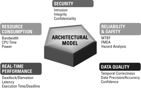
The property and annex annotations of the AADL model support the generation of analytical models for different quality attributes from the same architecture model, as shown in Figure C.1 (Lewis and Feiler 2008).
Figure C.1 Multiple dimensions of architecture analysis in AADL
C.2 Documenting a Module Style
Although AADL does not use the term “module,” AADL can represent units of implementation and relations among them. An AADL model is organized into packages, each of which defines a namespace. Packages can be placed into a nested naming hierarchy similar to Java packages. A package contains component specifications and may specify use of components from other packages. A package has a public part containing component specifications accessible to other packages and a private part containing component specifications local to the package. The package and its component specifications are maintained in an XMI representation based on the standardized AADL Meta-Model and have both a textual and graphical presentation. The graphical presentation may show subsets of the underlying model according to a specific view point.
Component types can be defined in terms of other component types through an extends relation (expressed by the extends keyword in textual AADL). This relation corresponds to the generalization concept in UML. This permits an incomplete component type that acts as a template to be refined by completing the specification of features and properties, and to be extended with additional features. These component types effectively represent a family of interfaces for a component.
Multiple component implementations can be associated with a component type through a realization relation expressed by naming the type as part of the implementation specification. They represent variants of a component. Implementations themselves can be refinements and extensions of other implementations. These incomplete component types and component implementation can be explicitly parameterized. This allows us to model architecture patterns, reference architectures, and families of system architectures (Feiler et al. 2004, Feiler 2007, Feiler et al. 2009).
Figure C.2 shows the specification of a landing gear with features indicating that it requires access to an electrical power source, a hydraulic power source, and a signal flow. The component as well as its features can have properties. In our example, the landing gear has a weight property, a property providing traceability to a requirement, and an indication of the intended tier in a multi-tier architecture. The properties of the landing gear features indicate their electrical and hydraulic power requirements.
Figure C.2 Specification sheet of a landing gear

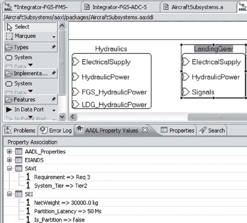
A graphical view of this component specification is shown in Figure C.3. It shows the landing gear with its features on the right. At the bottom is a property viewer that shows the properties associated with the landing gear specification. You can create a new component specification by selecting the appropriate component category from the palette on the left and by adding features from the palette into the component type.
Figure C.3 Graphical view of component specification
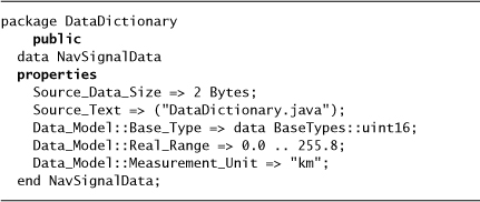
Users can define data types using the AADL data component type. Such data type specifications can be placed in a separate package, which we call DataDictionary in our example in Figure C.4. This specification may characterize the data type in source code with properties relevant at the architecture level, such as the size of the data type, its source file, its base type representation, and constraints on the data value and its measurement unit. Data component types can have provided subprogram features to reflect methods on classes. The internal details of such data types may have been declared in a programming language or expressed in a data modeling notation such as UML class diagrams, or they can be expressed in AADL.
Figure C.4 User-defined data types
A component implementation acts as a blueprint of the realization of a component. Figure C.5 illustrates such a blueprint for the implementation of a flight manager process. It consists of several threads as subcomponents of the process. Connections indicate how these threads communicate with each other and with components outside the process through the features of the process interface, which are shown on the left. In this case the port group graphic is expanded to show the elements of the port group, such that individual ports of the port group can be connected.
Figure C.5 Component blueprint of a flight manager

C.3 Documenting a Component-and-Connector View
Each AADL component category has well-defined semantics, many of which correspond to components in a component-and-connector (C&C) view. For example, AADL threads model concurrent tasks or active objects that represent sequential execution of source code. A thread is bound to a virtual processor or processor for execution. AADL threads can be dispatched periodically or triggered by events or the arrival of messages. In the latter case, a thread may execute aperiodically, that is, in response to the arrival of an event or message. If the thread is already active, newly arriving events or messages are queued. A thread may execute sporadically; that is, it will respond to events and messages, but its execution will be limited to a maximum rate. A thread may have a dispatch protocol called timed; that is, it will respond to events or messages like an aperiodic thread, but it will time out after a specified period if no event or message arrives. A thread may be declared with a hybrid dispatch protocol; that is, it executes periodically and it responds to events and message arrivals. A thread may be dispatched as a background thread; that is, it is dispatched once and executes until completion. The semantics of these dispatch protocols and the scheduling states of threads, such as suspended, ready, and running, are defined precisely in the standard using hybrid automata.
An example of a component specification for a process is shown in Figure C.6. An AADL process represents a space partition; that is, it provides runtime address space protection from other processes. It illustrates that at every level of the component hierarchy, we specify the complete interface of a component and its subcomponents to outside components. It also illustrates the use of port groups to indicate a collection of ports through which this process interacts with other software components. The interaction with other components will be specified through a single port group connection instead of separate connections for each port.
Figure C.6 Software process with port groups

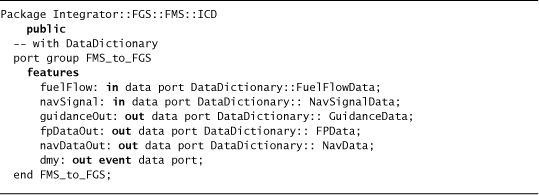
The details of interaction in terms of ports are specified separately in a port group type declaration that can be placed in a separate AADL package, as shown in Figure C.7. In our example, one port group consists of two incoming ports and four outgoing ports.
Figure C.7 Port group specifications
Port-based communication may be in the form of messages (AADL event data port), in the form of events (AADL event port), and in the form of state data (AADL data port). Event data ports and event ports have queues associated with them. In addition, arrival of messages or events can trigger the dispatch of a thread according to its dispatch protocol. Data ports and event data ports are typed with user-defined data types, and only ports with compatible data types can be connected.
In AADL the connection concept is used to connect component ports, subprogram features, or access features. Connections can have properties, such as properties that indicate the desired protocol or quality of service provided by a protocol, such as guaranteed delivery. The connection is then bound to a virtual bus or bus that acts as the logical connector in terms of protocols, or a physical connector to perform the communication between different hardware components of the sender and receiver.
AADL supports directional flow through ports and connections. The threads may perform periodic sampled processing of signal streams, such as control systems, including communication timing semantics that ensure deterministic sampling. Threads may also perform data-driven message processing, processing of discrete events, and periodic processing of alarms. In addition to port-based communication, AADL supports modeling of access to shared data components with concurrency control—for example, blackboard architectures—and shared access to bus components for communication between hardware components. Finally, AADL supports interaction between threads and with devices through subprogram calls to model service calls.
AADL distinguishes between a set of component specifications and blueprints and an instance of a system model. An instance model is the result of instantiating a top-level system implementation recursively. Typically, such a system consists of the application software, the computing platform, and the physical environment. The AADL standard has defined a separate XMI representation of an instance model that analysis tools can operate on directly, or from which analytical models and runtime executives can be generated.
The instance model represents the complete component containment hierarchy, as illustrated in Figure C.8. Connection instances are between the components that are the leaves of the component hierarchy, for example, between thread instances or between processor instances and bus instances. The AADL standard does not require the full component containment hierarchy to be reflected in the instance model; instance models may be flattened to include only component instances with connection instances.
Figure C.8 Component containment hierarchy of system instance model
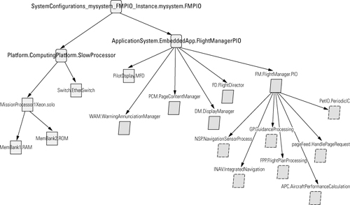
AADL supports the instantiation of incomplete system models. This allows such models to be analyzed early in the development life cycle and the analyses revisited as the model is refined. For example, only one process has been expanded to the thread level. For such a model we can still perform resource budget analysis by rolling up the data from threads and comparing it against the resource budgets of the processes. Those budgets are compared against the capacity available through the hardware.
AADL supports the analysis of critical flows throughout a system by providing the capability to specify end-to-end flows and annotating them with relevant flow properties, such as latency, precision, and confidentiality. An end-to-end flow is specified in terms of a sequence of component flow specifications and connections. A component flow specification specifies a flow from a component input (port) to one of its outputs (ports) without having to expose the component implementation. This allows end-to-end flow analysis, such as latency analysis, to be performed on systems of systems based on specified flow properties, while implementations of individual systems can be separately validated to ensure they meet the specified flow property.
C.4 Documenting a Deployment View
A complete AADL model of an embedded system includes software components, computer hardware components, and components of the physical system. The application software has to be deployed on the computer hardware in order for us to be able to perform analysis of operational quality attributes, such as meeting timing, performance, reliability, safety-criticality, and security requirements.
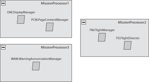
Figure C.9 shows a graphical representation of the deployment view, as it is often found in architecture documents. It shows the computer hardware components and the software components placed inside them to indicate that they are bound to the respective hardware component. This deployment information is recorded through properties for processor binding, memory binding, and connection binding. This deployment information can be declared as a collection of property values at the top of the model and refer to both the processes and threads to be bound to processors, memory, and buses.
Figure C.9 Graphical representation of a deployment view
C.5 Documenting Behavior
AADL supports modeling of a variety of system behaviors. The AADL mode and mode transition concept allows users to specify operational modes, different property values for different modes, and different runtime configurations of components and connection for different modes. For example, it can define different sets of threads and port connections during the taxiing mode of an aircraft and a cruise mode.
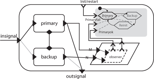
AADL modes can also be used to define different fault-tolerant configurations. This is illustrated by the architecture redundancy pattern shown in Figure C.10. It shows a replicated component with an observer to determine its health. The replicated component can be a software component or a hardware component. In a hot standby pattern, both the primary and the backup components are active in primary and backup mode; in a passive backup pattern, only one of the components is active at a time. Event-triggered mode transitions the dynamic aspects of switching between these configurations. These architecture patterns can be associated with the architecture as aspects without cluttering the primary functional view.
Figure C.10 Dual redundancy pattern
The AADL property set mechanism allows users to introduce new properties in support of certain analyses. For example, the security behavior of security frameworks, such as the Bell LaPadula and Chinese Wall frameworks, can be expressed as properties on existing AADL model concepts (Hansson and Feiler 2008). Figure C.11 illustrates the definition of security classifications as an enumeration type that is then used to define security properties with values of that type.
Figure C.11 User-defined properties

AADL also supports the use of a sublanguage in AADL model annotations. Figure C.12 shows the specification of an error state machine using the AADL Error Model Annex sublanguage (Rugina et al. 2008). This error machine specifies fault-free states and error state, intrinsic faults and error propagations with probability of occurrence, and conditions under which error states can change.
Figure C.12 An example of the Error Model Annex sublanguage

An error state machine is associated with a component type or component implementation. As a result, this error state machine is attached to each instance of this component. The error state machines of different components interact by propagating errors based on the logical and physical connectivity as well as the deployment of software to hardware.
AADL also has a draft Behavior Annex standard that was due to be published at the time of this writing. The focus of this annex is to support the specification of component interaction behavior and discrete state behavior within components.
C.6 Documenting Interfaces
A component type declares the interface of a component to other components, provides a specification of services, and presents its resource requirements on the hardware platform. The AADL feature concept is used to represent both provided and required features through which the component interacts with other components. AADL supports three types of interactions between components: (1) port-based flow of data, events, and messages from one component to another; (2) communication through shared access to a common resource, such as a shared data component; and (3) calls on subprograms to request services with returning results. AADL also supports the concept of a flow specification to represent the flow through a component without requiring access to its implementation. Flow specifications can have properties such as the expected latency of a flow through the component. They support end-to-end flow analysis of large-scale systems.
C.7 Summary
AADL supports modeling of the static structure and interaction topology, as well as the dynamic nature of system architectures. The dependencies and the hierarchy reflected in the AADL model are a good basis for analysis of quality attributes that focus on the design of an architecture, such as modifiability. AADL models include the task and communication architecture of application software, the runtime architecture and hardware platform, and the deployment of the former on the latter to support the analysis of operational quality attributes, such as availability.
The AADL standard includes a standard interchange format for models in terms of XMI. This interchange format facilitates integration with existing tools and interchange of AADL models between projects and organizations. There is an open-source tool set for AADL (called OSATE) (SAE AADL 2010) based on Eclipse, as well as commercial tool support. A number of architecture analysis tools as well as automatic generators of runtime executives have been integrated with these AADL tool sets.