E. Epilogue: Using Views and Beyond with Other Approaches

The word architecture goes back through Latin to the Greek for “master builder.” The ancients not only invented the word, they gave it its clearest and most comprehensive definition. According to Vitruvius—the Roman writer, whose Ten Books on Architecture is the only surviving ancient architectural treatise—architecture, is the union of “firmness, commodity, and delight”; it is, in other words, at once a structural, practical, and visual art. Without solidity, it is dangerous; without usefulness, it is merely large-scale sculpture; and without beauty . . . it is not more than utilitarian construction.
—Marvin Trachtenberg and Isabelle Hyman, Architecture: From Prehistory to Post-Modernism/The Western Tradition (1986, p. 41)
This book has presented guidance, which we call the Views and Beyond approach, for assembling a package of effective, usable documentation for a software architecture. Using a basic set of concepts (views and styles) and an organizing principle (module views, component-and-connector (C&C) views, allocation views), we have shown how to document a wide range of architecture-centric information: from structure to behavior to interfaces to rationale. The book stands on its own as a complete handbook for documentation.
But the book does not exist in a vacuum. Other writers, on their own or under the auspices of large organizations or standards bodies, have prescribed specific view sets or other approaches for architecture. There is now an ISO standard for architecture documentation. Many people are writing about how to document an “enterprise architecture.” It may not be clear whether the advice in this book is in concert or in conflict with these other sources. In some cases, it isn’t clear whether there’s a relationship at all.
The purpose of this chapter is to answer the following questions:
How do I use the Views and Beyond approach if I want to produce software architecture documentation that. . .
1. . . . is compliant with the ISO standard for architecture documents?
2. . . . adheres to the Rational Unified Process 4+1 approach to documentation?
3. . . . uses the Rozanski/Woods viewpoint set?
4. . . . supports an Agile development project?
Over and above these software-oriented variations, this chapter also covers the U.S. Department of Defense Architecture Framework (DoDAF), which is not intended for software architectures but nevertheless is sometimes pressed into service in that way.
E.1 ISO/IEC 42010, née ANSI/IEEE Std 1471-2000
With Rich Hilliard and David Emery
E.1.1 Overview
![]()
What ISO 42010 calls an architecture description is what the Views and Beyond approach calls an architecture document. See “Coming to Terms: Specification, Representation, Description, Documentation” on page 10, in the prologue, for why we chose the term we did. In this section, we will defer to the ISO’s terminology.
ISO/IEC 42010 (or “eye-so-forty-two-ten” for short) is the ISO standard, Systems and software engineering—Architecture description. The first edition of that standard was published in 2007. It was the fast-track adoption by ISO of IEEE Std 1471-2000, which was developed by an IEEE working group drawing on experience from industry, academia, and other standards bodies between 1995 and 2000. ISO 42010 is centered on two key ideas: a conceptual framework for architecture description and a statement of what information must be found in any ISO 42010-compliant architecture description.1
Under ISO 42010, as in the Views and Beyond approach, views have a central role in documenting software architecture. The architecture description of a system includes one or more views.
![]()
ISO 42010 defines a view as a “work product representing a system from the perspective of architecture-related concerns.”
Figure E.1 illustrates the core concepts of architecture description in the standard:
Figure E.1 Core concepts of ISO/IEC 42010:2007

![]()
ISO 42010 defines system of interest as encompassing “individual applications, systems in the traditional sense, subsystems, systems of systems, product lines, product families, whole enterprises, and other aggregations of interest.”
Under ISO 42010, an architecture description is a work product—a concrete artifact (which could be a document or repository) that documents the architecture of a system of interest. A system of interest exists in some environment (containing other systems, humans, and so on), which motivates, constrains, and interacts with the system of interest. ISO 42010 requires that an architecture description contain the following:
• Identification of the stakeholders for the architecture and the system of interest
• Identification of the architecture-related concerns of those stakeholders
![]()
ISO 42010 defines viewpoint as a work product establishing the conventions for the construction, interpretation, and use of architecture views and associated architecture models.
• A set of architecture viewpoints defined so that all of the stakeholder concerns are covered by that set of viewpoints
• A set of architecture views, such that there is one view for each viewpoint
• A set of architecture models from which the views are composed
• Architecture rationale to record key decisions
ISO 42010 is based on the following tenets:
1. Architecture is an abstraction; the standard deals with the work product used to capture an architecture, namely, the architecture description.
2. An architecture description is inherently multi-view. No single view is sufficient to capture an architecture because architecture is multi-disciplinary, with multiple stakeholders and multiple architecture-related concerns that the architect must deal with.
3. It is useful to separate viewpoints (perspectives on the architecture) from views (what is captured in the description of a specific architecture from the perspective of a viewpoint for a system of interest). This distinction was motivated by the body of existing practice that defines viewpoints for a number of architecture-related concerns. (However, the term viewpoint was introduced in the standard for this notion.)
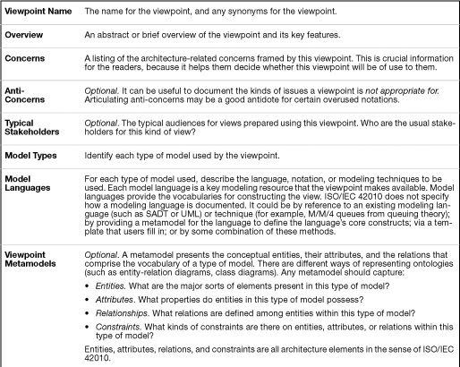
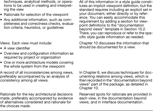
4. There should be a viewpoint for each view. Just as every map should have a legend, each view should have a viewpoint explaining the conventions being used in that view. Figure E.2 illustrates one possible template for a viewpoint.
Figure E.2 Template for a viewpoint

5. An architecture description is driven by stakeholders’ architecture-related concerns, because these reflect the issues the architect must deal with. Viewpoints are selected for use in an architecture description to ensure coverage of the identified architecture-related concerns.
One of the goals for the joint revision of ISO/IEC 42010:2007 was to align with existing ISO architecture efforts, specifically GERAM (ISO 15704 2000) and RM-ODP (ISO/IEC 10746-2 1996). The use of these standards, and existing architecture approaches such as Kruchten’s “4+1” approach (Kruchten 1995), Zachman’s Architecture Framework (Zachman 1987), and even the DoD Architecture Framework (DoDAF 2007), underscores the fact that many (if not most) practicing architects operate within an architecture framework. Each of these approaches could be considered as defining a set of viewpoints, and in fact it was the existence of such approaches that motivated the separation of viewpoint from view.
![]()
The Rational Unified Process and Kruchten’s “4+1” approach are discussed in Section E.2.
DoDAF is discussed in Section E.5.
The standard also establishes requirements for creating and documenting architecture frameworks. In the terms of the standard, an architecture framework specifies a set of stakeholders, a set of concerns, and viewpoints covering those concerns.
![]()
ISO 42010 defines an architecture framework as “conventions and common practices for architecture description established within a specific domain or stakeholder community.”
E.1.2 42010 and Views and Beyond
If you want to use the Views and Beyond approach to produce an ISO 42010-compliant architecture document, you certainly can. The main additional obligation is to choose and document a set of viewpoints and (to a lesser degree) address ISO 42010’s required information content. Table E.1 summarizes the information required by the ISO 42010 standard and how the Views and Beyond approach addresses each one.
Table E.1 ISO 42010 information requirements and how we address them

E.2 Rational Unified Process/Kruchten 4+1
The Rational Unified Process (RUP) introduces a five-view approach to documenting software architectures, based on Kruchten’s 4+1 approach.
1. The logical view contains the most important design classes.
2. The implementation view captures the architectural decisions made for the implementation.
3. The process view documents the tasks—processes and threads—involved.
4. The deployment view documents the various physical nodes for the most typical platform configurations.
5. The use case view or “plus-one view” contains use cases and scenarios of architecturally significant behavior.
The RUP describes the use case view as a representation of an architecturally significant subset of the use case model, which documents the system’s intended functions and its environment. The use case view serves as a contract between the customer and the developers and represents an essential input to activities in analysis, design, and test. It also serves as a design check on the other views: It is incumbent upon the architect to show how each of the other views correctly supports the use cases in the use case view. If they do, then this suggests that they are correct and consistent with each other.
E.2.1 RUP/4+1 and Views and Beyond
If you want to use the Views and Beyond approach to document a 4+1 architecture, you can easily do so.
• Documenting a logical view of the RUP can be done by using certain module or C&C styles. A union of the decomposition style, the uses style, and the generalization style allows you to represent the structural part of the logical view by using such elements as subsystems and classes, whereas a C&C style (which one depends on the design you chose) allows you to represent the runtime aspects by using components and ports.
![]()
The decomposition style is covered in Section 2.1.
The uses style is covered in Section 2.2.
The generalization style is covered in Section 2.3.
• An implementation view can be represented by using a combination of the decomposition style, the layered style, the uses style, and the generalization style. The implementation view represents implementation elements, such as implementation subsystems and components. The RUP distinguishes between a design and an implementation model to separate general design aspects from implementation aspects introduced by the use of a specific programming language. To describe the relations between elements of the design model and the implementation model, the mapping should be documented. To show how the implementation elements are stored in a file system during development, use the Views and Beyond implementation view.
![]()
The implementation style is discussed in Section 5.5.
• The RUP process view provides a basis for understanding the process organization of a system, illustrating the decomposition of a system into processes and threads and perhaps also showing the interactions among processes. The process view also includes the mapping of classes and subsystems onto processes and threads. To accommodate the process view, define a style that uses components such as those defined in the C&C communicating-processes style—task, process, thread—and specific refinements of the communication connectors, such as RPC or broadcast. To describe the relations between processes and elements, such as subsystems and classes, the mapping among them should be documented.
![]()
The C&C communicating-processes style is covered in Section 4.6.1.
• A RUP deployment view describes one or more physical network—hardware—configurations on which the software is deployed and runs. This view also describes the allocation of processes and threads—from the RUP process view—to the physical nodes. The deployment style is a good match for the RUP deployment view. The RUP deployment view also allows you to assign deployment units to nodes. A deployment unit consists of a build—an executable—documents, and installation artifacts. It is a packaging of implementation elements for selling and/or downloading purposes. To achieve this, you can define a style showing implementation elements—subsystems/classes—and how they are packaged as deployment units.
![]()
The deployment style is covered in Section 5.2.
Finally, use cases are a vehicle for describing behavior, and behavior is a part of every view’s supporting documentation. Consequently, you can document use cases as behavior documentation for the system or parts of it. You can also document the use case view in the mapping to requirements.
![]()
Behavior documentation is covered in Chapter 8.
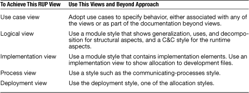
Table E.2 reconciles the prescribed Rational Unified Process views with our advice in this book.
Table E.2 Relating Views and Beyond to RUP
![]()
The mapping of an architecture to its requirements is covered in Section 10.3.
Beyond its five views, RUP does not prescribe other kinds of documentation, such as interface documentation, rationale, or behavior of ensembles. It doesn’t call for a documentation roadmap, a mapping between views, view templates, or style guides. But it certainly does not rule these things out, either, so don’t forget to add them.
You are free to consider additional views that may be important in your project’s context, and you should do so. You should augment the primary presentation of each view with the supporting documentation called for in Section 10.2.1, and you should complete the package by writing the documentation that applies beyond views, as described in Section 10.2. The result will be a RUP-compliant set of documentation having the necessary supporting information to complete the package.
E.3 Using the Rozanski and Woods Viewpoint Set
With Nick Rozanski and Eoin Woods
In 2005, the two coauthors of this section, Nick Rozanski and Eoin Woods, wrote a very useful book on the design and documentation of software systems architecture (Rozanski and Woods 2005). In it, they prescribed a useful set of six viewpoints (in the ISO 42010 sense) to be used in documenting software architectures. The six viewpoints, based on an extension of the Kruchten 4+1 set, are shown in Figure E.3.
Figure E.3 The Rozanski and Woods viewpoint set (from Rozanski and Woods 2005, p. 213)

The views specified by their viewpoint set are the following:
• The functional view documents the system’s functional elements, their responsibilities, interfaces, and primary interactions. A functional view is the cornerstone of most architecture documents and is often the first part of the documentation that stakeholders try to read. It drives the shape of other system structures such as the information structure, concurrency structure, deployment structure, and so on. It also has a significant impact on the system’s quality properties, such as its ability to change, its ability to be secured, and its runtime performance.
• The information view documents the way that the architecture stores, manipulates, manages, and distributes information. The ultimate purpose of virtually any computer system is to manipulate information in some form, and this viewpoint develops a complete but broad view of static data structure and information flow. The objective of this analysis is to answer the important questions around content, structure, ownership, latency, references, and data migration.
• The concurrency view describes the concurrency structure of the system and maps functional elements to concurrency units to clearly identify the parts of the system that can execute concurrently and how this is coordinated and controlled. This entails the creation of models that show the process and thread structures that the system will use and the interprocess communication mechanisms used to coordinate their operation.
• The development view describes the architecture that supports the software development process. Development views communicate the aspects of the architecture of interest to those stakeholders involved in building, testing, maintaining, and enhancing the system.
• The deployment view describes the environment into which the system will be deployed, including capturing the dependencies the system has on its runtime environment. This view captures the hardware environment that the system needs, the technical environment requirements for each element, and the mapping of the software elements to the runtime environment that will execute them.
• The operational view describes how the system will be operated, administered, and supported when it is running in its production environment. For all but the simplest systems, installing, managing, and operating the system is a significant task that must be considered and planned at design time. The aim of the operational view is to identify system-wide strategies for addressing the operational concerns of the system’s stakeholders and to identify solutions that address these.
Coming to Terms: Architecture Perspectives
An architecture perspective defines a number of activities, tactics and guidelines for a set of related quality properties. For example, a resilience perspective might include activities such as confirming availability requirements and schedule; estimating the availability of individual components; and deriving the overall platform and service availability. It might include tactics for achieving high availability, such as use fault-tolerant hardware; use clustering and load balancing: and use software availability solutions such as redundant logging and up-to-the-minute data restoration. Notice that a perspective is somewhat more restrictive than a viewpoint as defined in ISO 42010.
![]()
An architecture perspective is “a collection of activities, tactics, and guidelines that are used to ensure that a system exhibits a particular set of related quality properties that require consideration across a number of the system’s architectural views” (Rozanski and Woods 2005).
Architecture perspectives formalize an activity that good architects do as a matter of course, namely, ensuring that a system exhibits the right quality attribute properties, such as resilience, scalability, security, or extensibility.
This typically requires consideration of the system across a number of its architecture views. For example, achieving good performance requires consideration of the system’s functional and concurrency structures, the way it manages and accesses information, and how it is deployed on physical hardware and software.
Having started to design the architecture of the system, and documented the architecture in a number of views, the architect therefore applies the perspective to the views to assess its capabilities against those quality properties. Applying a perspective does not result in a new view, but rather, it may result in a number of modifications to existing views to help address stakeholder concerns.
![]()
See Section 9.1 for more information about stakeholders and their documentation needs.
Applying perspectives enables the architect to identify any weaknesses or omissions in the architecture, and to suggest enhancements or extensions to it. This leads to insights into the architecture (for example, understanding better where its single points of failure are), improvements to it (such as adding redundant hardware or software components to reduce the likelihood of catastrophic failure), and artifacts (such as service availability models).
If you wish to document perspectives prescribed by the Rozanski and Woods approach, you can do so by supplementing your documentation as follows:
The template for documentation beyond views includes a documentation roadmap. Supplement this roadmap with a description of the perspectives applied to the architecture. These descriptions can be found in the perspective catalog and can be included in the roadmap directly or by reference. Complement the mapping between views with a mapping between perspectives and views. Stakeholders wishing to understand how their concerns are met can look at the applicable perspectives to see which views are involved.
![]()
See Figure 10.4 in Section 10.2 for the template for documentation beyond views.
The template for a view packet is the place to record more-detailed information. Capture the explanation for design decisions that resulted from the application of the perspective under rationale, and capture references to the concern that motivated the perspective under other information.
![]()
See Figure 10.1, in Section 10.1, for the template for a view.
E.3.1 Rozanski and Woods Viewpoints and Views and Beyond
This set of viewpoint definitions is not prescriptive about the notations or modeling approaches that should be used in each view. Instead, the viewpoints define the type(s) of models expected in each view and the information that should be captured in each, suggesting possible modeling approaches for each. Therefore, it is perfectly possible to use this viewpoint set in conjunction with the documentation approaches described by the Views and Beyond approach.
• A functional view contains a functional structure model, comprising a set of functional elements, interfaces offered by the elements, connectors between the elements, and external entities that the system’s elements interact with. Such a functional view can be documented using a C&C style, using components and ports to model the functional elements and their interfaces and connectors to link them together.
• An information view may contain a wide variety of models related to the information in the system, including static data structure models, information flow models, information life-cycle models, and data ownership models. Here, the data model view directly applies. Data flow can also be documented as a C&C or module style.
![]()
Data model views are described in Section 2.6.
• A concurrency view may contain a system-level concurrency model, showing architecturally significant process and thread structures, and a state model, showing the valid states and transitions of any system elements with complex life cycles. The concurrency model may contain processes, process groups, threads, and interprocess communication mechanisms. The state models contain the familiar state machines, made up of states, transitions, events, and actions. The concurrency model can be documented using the C&C communicating-processes style, and as mentioned earlier when discussing documenting behavior, state models can be naturally captured as state machines.
• A development view may contain a module structure model (showing how the implementation modules are organized), common design models (describing system-wide design conventions), and codeline models (explaining how the source code is organized and built). Of these, the module structure model can be very naturally captured using the module decomposition, uses, or layered styles, while the allocation implementation style may well be helpful in representing a codeline model. The common design model (dealing with functions such as initialization, termination and restart, and message logging) can be captured in the architecture background section of the view packet template under assumptions that pertain to the development environment. These assumptions place design constraints on the developers to maximize commonality across element implementations. These constraints might be recorded in textual form or in the form of design patterns using more specific notations (such as UML).
• A deployment view may contain a runtime platform model, showing how the system is deployed to production; a network model, showing its networking requirements; and technology dependency models, showing the requirements that the system has on its runtime environment. Of these, the runtime platform model and network model are both naturally documented using the allocation deployment style. The technology dependency models simply record the technology dependencies of each part of the deployment environment (that is, required libraries, middleware, and so on). These can be captured using a uses style (represented as a simple table).
• Finally, an operational view can contain models relating to system installation, system migration strategy, operational configuration management approach, administration, and system support. These models capture requirements of the operating environment that influence the architecture. Like any other requirements, they can be part of the documentation beyond views. Solutions can be captured in one or more existing views such as the allocation install style, a C&C repository style, or the uses style, showing guidelines for monitoring and message logging.
Table E.3 summarizes the discussion.
Table E.3 Relating Views and Beyond to the Rozanski and Woods viewpoint set

![]()
The data model style is covered in Section 2.6.
The communicating-processes style is covered in Section 4.6.1.
The layered style is covered in Section 2.4.
The implementation style is covered in Section 5.3.
Documentation of assumptions is part of rationale. See Section 6.5.
The deployment style is covered in Section 5.2.
Documentation beyond views is covered in Section 10.2.
E.4 Documenting Architecture in an Agile Development Project
E.4.1 Overview
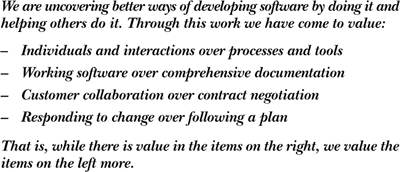
“Agile” refers to an approach to software development that emphasizes rapid and flexible development and deemphasizes project and process infrastructure for their own sake. Figure E.4 shows the “manifesto” for Agile software development that has served since 2001 as the movement’s Desiderata.
Figure E.4 The Manifesto for Agile Software Development (Agile Alliance 2002a)
There are many different methodological instantiations of the Agile approach. These include Extreme Programming (Beck and Andres 2004), Scrum (Schwaber 2001), Feature-Driven Development (Palmer and Felsing 2002), and Crystal Clear (Cockburn 2004). Practices that show up in one or more of the Agile methods include the following:
• User stories. Text specifies functional requirements describing the actions of people.
• Test-driven development. Developers create automated tests at the same time they write the tested code.
• Short iterations. The development plan consists of short iterations (a few weeks); also called sprints.
• Pair programming. Developers work in pairs, where one is typing the code and the other reviews the code looking for defects and ways to improve the design.
• Refactoring. As part of the implementation cycle, code is refactored to improve the internal structure and maintainability without altering the externally visible behavior.
For some, agility is used as an excuse to avoid disciplined development. The Dilbert cartoon in Figure E.5 represents this early view of the Agile world.
Figure E.5 Agile, as some imagined it. (DILBERT: © Scott Adams / Dist. by United Feature Syndicate, Inc.)

In fact, saying that Agile development is antithetical to documented development is simply not true, if indeed it ever was.
![]()
A recent survey shows that Agile teams are more likely to build models than traditional teams (Ambysoft 2008).
A related misconception is that in Agile, coding starts on day one of the project. In practice, the first iteration can go by with no production code written at all. This happens because the team is sorting out design alternatives and conducting technical experiments with different frameworks, platforms, or technologies.
The key goal of design and modeling in Agile projects is not to avoid designing, but to avoid “big design up front” (BDUF). Broad and far-reaching architecture strategies are worked out up front, but many other design decisions can be deferred until needed. They can be written down whenever they are made.
![]()
Use a standard organization in order to employ documentation as a receptacle to hold the results of design decisions as they are made.
Documented design decisions in Agile projects tend to be (but are not always) fewer in number and coarser in granularity than design decisions documented in traditional projects. This comes about because Agile developers are expected to have design skills, and Agile designers and architects are expected to have coding skills. So the communication of design decisions is shorter and denser; it’s rather like telling a story to a member of your family as opposed to a complete stranger.
E.4.2 Agile Development and Views and Beyond
The Views and Beyond and Agile philosophies agree strongly on a central point: If information isn’t needed, don’t document it. All documentation should have an intended use and audience in mind, and be produced in a way that serves both. One of the fundamental principles of technical documentation is “Write for the reader.” That means understanding who will read the documentation and how they will use it. If there is no audience, there is no need to produce the documentation.
![]()
The Seven Rules for Sound Documentation are given in Section P.5. of the prologue
Architecture view selection is an example of applying this principle. The Views and Beyond approach prescribes producing a view if and only if it addresses the concerns of an explicitly identified stakeholder community.
![]()
View selection is covered in Chapter 9.
Another central idea to remember is that documentation is not a monolithic activity that holds up all other progress until it is complete. The view selection method given in Chapter 9 prescribes producing the documentation in prioritized stages to satisfy the needs of the stakeholders who need it now.
Cockburn expresses a similar idea this way: “The correct amount of documentation is exactly that needed for the receiver to make her next move in the game. Any effort to make the models complete, correct, and current past that point is a waste of money” (Cockburn 2002). The trick is knowing who the receivers are and what moves they need to make. Remember that the receiver might be a maintainer whose job begins long after the system is first fielded and the development team is disbanded.
With that in mind, the following is the suggested approach for producing Views and Beyond-based architecture documentation using Agile principles:
1. Adopt a template or standard organization to capture your design decisions.
2. Plan to document a view if (but only if) it has a strongly identified stakeholder constituency.
3. Fill in the sections of the template for a view, and for information beyond views, when (and in whatever order) the information becomes available. But only do this if writing down this information will make it easier (or cheaper or make success more likely) for someone downstream doing their job.
Actually, this three-step approach is the entire Views and Beyond approach in a nutshell: Have a template. Fill it in as you go. Only write down what’s worth writing down. For an Agile project, the emphasis shifts to the guidance about not doing things, which is implied by the “only if” clauses.
![]()
See the formula for the economics of documentation in Section P.2.4 of the prologue.
Beyond this strategic guidance, you can also use the following advice:
• Stop designing as soon as you feel you’re ready to start coding. Don’t worry about creating an architectural design document and then a finer-grained design document. Produce just enough design information to allow you to move on to code. Capture the design information in a format that is simple to use and simple to change—a wiki, perhaps. In the next sprint, you can expand the existing design as needed in order to capture design decisions required to implement the features listed for that sprint.
![]()
Using a wiki to capture an architecture is discussed in Section 10.4.2.
• Don’t feel obliged to fill up all sections of the template, and certainly not all at once. We still suggest you define and use rich templates because they may be useful in some situations. But you can always write “N/A” for the sections for which you don’t need to record the information (perhaps because you will convey it orally).
![]()
The fourth principle of sound documentation in the prologue tells us that it’s better to write “N/A” or “TBD” than leave sections blank. You shouldn’t remove the section headers either; otherwise, your document will end up with a different structure than the template.
Using a view template such as the one in Section 10.1, the ultimate simplification is to add the primary presentation and leave all other sections marked as “N/A”. In Agile teams, modeling sometimes happens as brief discussions by the whiteboard. In your view, the primary presentation may have a digital picture of the whiteboard and nothing more. Further information about the elements (element catalog), rationale discussion (architecture background), variability mechanisms being used (variability guide), and all else will be communicated verbally to the team—at least for now. Later on, if you find out that it’s useful to record a piece of information about an element, a context diagram, rationale for a certain design decision, or something else, you can replace the “N/A” with the corresponding piece of information.
• If it’s not worth updating the design, throw it away. As an example, suppose you created a sequence diagram that became part of the architecture documentation. In the implementation, you started off following what’s in the sequence diagram. However, you found better ways to implement that transaction and the end result turned out to be fairly different from the sequence diagram. The original diagram fulfilled its primary purpose by guiding the initial implementation. What should you do with the diagram now? You can:
– Leave it as is. This is the worst option, because now the documentation will be at odds with the implementation. Nothing makes a reader flee from documentation faster than the discovery that it is out of date, and now the reader won’t trust any other part of the architecture documentation, either.
![]()
Sequence diagrams can be used to document behavior. Sequence diagrams are covered in Section 8.3.2.
– Update the diagram. This is the ideal option, given you have time for that. The updated diagram will help maintainers who will need to understand that part of the implementation.
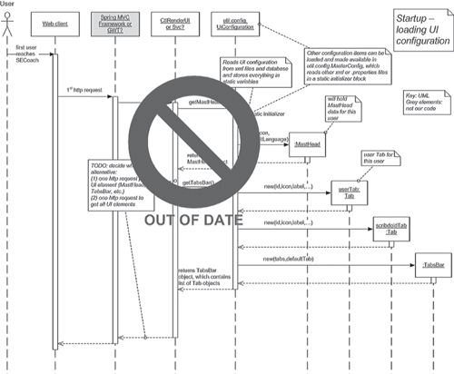
– Remove or cross off the diagram. This option is the realistic choice in many projects. The diagram is out of date; you’re better off removing it or marking it as out of date or no longer authoritative (Figure E.6 shows an example) so it won’t mislead readers of the documentation. In Agile projects, code, code comments, and associated unit tests often serve as the authoritative documentation for local (element-specific) designs.
Figure E.6 The architect decided not to update this diagram, but he didn’t want to delete it either. So he marked the diagram to prevent others from consuming out-of-date information.
• Many times, sketches are all you need. Don’t spend time crafting the neatest diagram using the latest and richest notation available. Don’t spend money on sophisticated modeling tools if you just need to draw simple diagrams. In many Agile projects, especially the ones with small, collocated teams, the true value of design diagrams comes from drawing them, which forces you to think through the issues; once the issues are solved, the documentation can be refined. Many times the design is represented as a sketch on a whiteboard or piece of paper. Figure E.7 shows an example.
Figure E.7 Sketch of a C&C view on the whiteboard

![]()
If a sketch successfully conveys the design to the development team, you can use it as the primary presentation in an architecture view.
E.5 U.S. Department of Defense Architecture Framework
With Don O’Connell
![]()
In this section, all quoted material and figures come from DoDAF 2007 (online at www.defenselink.mil/cio-nii/docs/DoDAF_Volume_I.pdf).
E.5.1 Overview of DoDAF
The DoDAF is the U.S. Department of Defense’s framework standard on how to document an architecture. According to the DoD:
The DoDAF provides the guidance and rules for developing, representing, and understanding architectures based on a common denominator across DoD, Joint, and multinational boundaries. It provides insight for external stakeholders into how the DoD develops architectures. The DoDAF is intended to ensure that architecture documentation can be compared and related across programs, mission areas, and, ultimately, the enterprise, thus, establishing the foundation for analyses that supports decision-making processes throughout the DoD.
![]()
The U.K. Ministry of Defence employs a similar framework called MoDAF.
The DoDAF defines a set of products that act as mechanisms for visualizing, understanding, and assimilating the broad scope and complexities of an architecture description through graphic, tabular, or textual means. These products are organized under four views: [operational view (OV), systems and services view (SV), technical standards view (TV), and all-view (AV)]. Each view depicts certain perspectives of an architecture as described below.
The OV captures the operational nodes, the tasks or activities performed, and the information that must be exchanged to accomplish DoD missions. It conveys the types of information exchanged, the frequency of exchange, which tasks and activities are supported by the information exchanges, and the nature of information exchanges. . . .
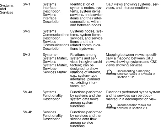
The SV captures system, service, and interconnection functionality providing for, or supporting, operational activities. DoD processes include warfighting, business, intelligence, and infrastructure functions. The SV system functions and services resources and components may be linked to the architecture artifacts in the OV. These system functions and service resources support the operational activities and facilitate the exchange of information among operational nodes. . . .
The TV is the minimal set of rules governing the arrangement, interaction, and interdependence of system parts or elements. Its purpose is to ensure that a system satisfies a specified set of operational requirements. The TV provides the technical systems implementation guidelines upon which engineering specifications are based, common building blocks are established, and product lines are developed. It includes a collection of the technical standards, implementation conventions, standards options, rules, and criteria that can be organized into profile(s) that govern systems and system or service elements for a given architecture. . . .
[The AV captures the] overarching aspects of an architecture that relate to all three views. The AV products provide information pertinent to the entire architecture but do not represent a distinct view of the architecture. AV products set the scope and context of the architecture. The scope includes the subject area and time frame for the architecture. The setting in which the architecture exists comprises the interrelated conditions that compose the context for the architecture. These conditions include doctrine; tactics, techniques, and procedures; relevant goals and vision statements; concepts of operations (CONOPS); scenarios; and environmental conditions.
The relations among these views are shown in Figure E.8.
Figure E.8 All-view describes the overall context of the system. Operational views are largely contextual, concept-of-operations, and capability diagrams and tables. Systems and services views are largely the nodes and interconnectivity, with numerous products showing various functions and behaviors. Technical standards views are about current and future technical standards.

E.5.2 DoDAF and Software Architecture
Although DoDAF is quite reticent about pronouncing what kind of architecture it was intended to capture—software? system? enterprise?—it is quite clear that it was not intended to capture software architectures.
Generally speaking, DoDAF views provide the following relevant software architecture information.
1. Context and scope of the architecture
2. Key capabilities provided by the system, the key mission threads, the operational nodes and their mission activities
3. The system nodes and primary data flows, the networks that connect those nodes, and the allocation of functionality to those system nodes
4. Optionally, performance, availability, information assurance, and interoperability behaviors
5. Deployment views, showing major software components and where they reside
6. Services, along with their capabilities and constraints
E.5.3 DoDAF and Views and Beyond
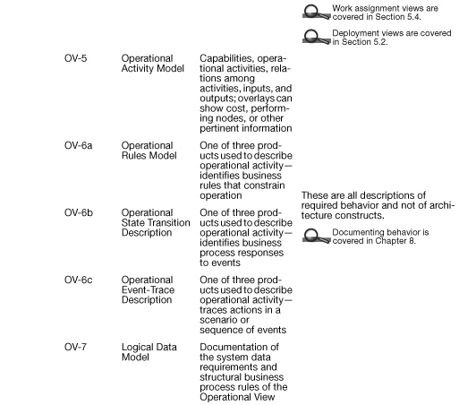
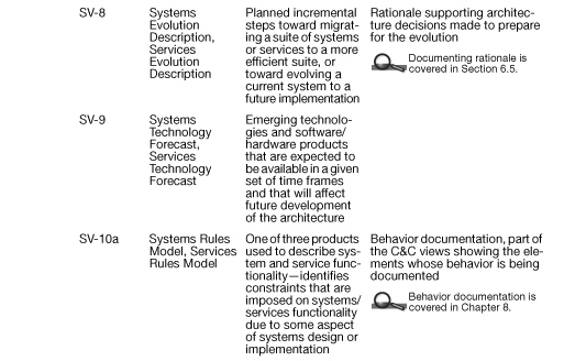
Table E.4 shows all of the DoDAF products, arranged by type of view. DoDAF is not a particularly suitable framework for software architecture; nevertheless, if you need to produce DoDAF documents, the rightmost column tells you the place in Views and Beyond documentation where you can record it.
Table E.4 DoDAF (v1.5) products and how the Views and Beyond approach can be used to capture their information


Generally, the following parts are missing from DoDAF to support a software architecture documentation:
1. Business environment and business drivers.
2. Architecture requirements in the form of quality attributes, plus customer inputs and prioritization of these attributes.
3. Architecture patterns and tactics, and the requirements that they address.
4. Module views showing the build-time relations and dependencies.
5. The SV views show a functional view of the architecture design. What is missing are the following notions:
a. Infrastructure (messaging, system management, failure detection and recovery, and so on).
b. Design patterns and other approaches to accomplish the quality attribute requirements.
c. Dynamic nature of deployments.
d. The OV-5 views are about mapping operational needs to functions. Software is often not built to these one-to-one mappings; thus, the mapping is not really possible. This mapping can be misleading.
6. Detailed software component interfaces. These are typically missing if the DoDAF views are describing a system of systems. These are also typically missing if DoDAF views are not constructed by software architects.
7. C&C view showing processes and threading of the software components. The notion of threads, interthread communications, multiple processes, and protected data is not supported.
E.5.4 A Strategy to Use DoDAF to Document Software Architecture
DoDAF, for all its attention to architecture, is a poor choice to represent software architecture. Its views were not created to support software architecture, and so unsurprisingly, they do a poor job of it. DoDAF simply speaks a different language, the language of systems and system-of-systems design. It is possible to shoehorn DoDAF into use by replacing its notion of “system” with the software architecture notion of “component,” but if you do that, make sure that all of your readers are in on the trick.
A charitable thing to say is that while DoDAF is certainly not sufficient for software architecture, some DoDAF products are useful in representing software architectures. So here’s a broad strategy:
• Include system-level behavior documentation as part of the DoDAF operational architecture view, concentrating on use cases that depict information exchange. Include this documentation in the “operational activity sequence and timing descriptions” products.
• Include element-level behavior documentation as part of the DoDAF systems architecture view. Include this documentation in the “systems activity sequence and timing descriptions” products.
• Include allocation views as part of the DoDAF system architecture view, where “physical resources” are documented.
• Include various module and C&C views as part of the DoDAF technical architecture view, appealing to it as the repository of “rules governing the arrangements, interaction, and interdependence of system parts” and “the criteria that describe compliant implementations.”
• For the information contained in the beyond views part of the documentation, DoDAF provides slots for overview and summary information and a dictionary. Use the former to hold the documentation roadmap, the view template, the system overview, and system-wide rationale. The latter can be home to the mapping between views, the element directory, and the glossary.
Specific DoDAF products that are useful for software architecture include the following:
• SV-5, which might be the starting point for a 4+1-style logical view.
• OV-2 and OV-3, where information exchange is covered.
• AV-1 and OV-1, which provide contextual views, and those are useful for software.
• OV-7 and SV-11, which show the logical data model and implementation of the data model.
DoDAF 2.0
As this book was going to publication, DoDAF version 2.0 was on the verge of release. Its goal, according to the DoD, is
to include further guidance on planning, developing, managing, maintaining, and governing architectures through a coherent semantic and structural metamodel. This version will place greater emphasis on a “data-centric” approach that facilitates the use of architecture by a wider variety of decision makers and will include additional information on federation for improved enterprise decisions.
Figure E.9, taken from the DoDAF 1.5 definition document, shows the evolution of DoDAF.
Figure E.9 Progression culminating in DoDAF version 2.0

E.6 Where Architecture Documentation Ends
Early in this book, we examined the question of where architecture ends and nonarchitectural design begins. A related question is where architecture documentation ends and other documentation issues begin. Architectures of all stripes exist. Security architectures, enterprise architectures, reference architectures, installation architectures: the list is endless.
Some of the terms are clearly in scope. Reference architectures, for instance, appeared in our discussion of documenting variation points in Chapter 6; the essence of a reference architecture is its ability to be tailored to the needs of any of a family of systems. Security architectures, although not addressed as such, are covered by making sure that a security specialist can find information of analytical use in one or more of the “normal” styles, such as those presented in Part I.
But some writers undoubtedly incorporate into architecture some aspects of system documentation that are outside the scope of this book. We completely agree with Boehm et al. (1999) that architecture is not an island and should be related to other important system development documents; however, all the organizations, templates, and guidelines in the Views and Beyond approach were created to capture software architectures. The artifacts we’ve prescribed let you capture “the set of structures needed to reason about the system, which comprise software elements, relations among them, and properties of both,” quoting from our definition of software architecture we gave at the outset.
How does the guidance in this book relate to architectures that occupy outlying regions of the topic area? To the extent that these “architectures” depend on architecture structures as captured by styles and views, the principles in this book hold. But writing down system installation procedures, for example, is not architectural. Nevertheless, the principles for sound documentation extend well beyond the realm of “mainline” architectures. Involvement of stakeholders, letting the uses of documentation guide its contents, controlling repetition, using a standard organization, avoiding ambiguity: these and other principles form the foundation of a high-quality documentation task.
Many other topics in software engineering are related to documenting software architecture. Chief among them is the general topic of software architecture. Other topics that you want to be aware of but that are outside the scope of this book are architecture description languages, commercial components, hypertext documentation, and configuration management.
E.7 A Final Word
Helping practitioners do their job more effectively is the goal of this book. We wanted to help an architect answer the question, “What do I do now?” Communicating the architecture is as important a task as creating it, for without effective communication, the architecture is nothing.
Architectures are too complex to be communicated all at once, just as a high-dimension object cannot be seen or grasped in its entirety in our three-dimensional world. As a way to divide and conquer complexity, views are by far the most effective means of architecture communication that we know. Styles and views establish a specialized and shared vocabulary, allow reuse of technical knowledge and practice from one system to the next, and facilitate analysis and prediction. Relating the views to one another and making the documentation accessible to its stakeholders completes the communication obligation to the present stakeholders. Capturing the rationale and why things are the way they are completes the communication obligation to the future.
That is the essence of documentation: recognizing and discharging the architect’s obligations to the community of stakeholders, present and future, whose needs the architecture is intended to serve. We hope that we have provided guidance that will lead to high-quality products and that is also practical and flexible enough to be useful in the resource-constrained, never-enough-time environments in which all architects labor.
And we look forward to discovering what’s on the horizon.
E.8 For Further Reading
The Internet contains a wealth of information about RUP, DoDAF, and ISO 42010. A good starting point for RUP is Philippe Kruchten’s original paper proposing the 4+1 approach for architecture; it is still the best introduction to that concept (Kruchten 1995).
The Web site Agile Modeling Practices, at agilemodeling.com/practices.htm, is a good repository for information about Agile practices. Other foundation works for Agile development include the following:
• Resources produced by the Agile Alliance:
– “Manifesto for Agile Software Development,” at agilemanifesto.org (Agile Alliance 2002a)
– The Agile Alliance Web site: agilealliance.org (Agile Alliance 2002b)
– “Principles Behind the Agile Manifesto,” at agilemanifesto.org/principles.html (Agile Alliance 2002c)
• Kent Beck and Cynthia Andres’s book Extreme Programming Explained: Embrace Change (2nd edition) (Beck and Andres 2004).
• Alistair Cockburn’s books:
– Agile Software Development (Cockburn 2002)
– Crystal Methodologies (Cockburn 2001)
– Crystal Clear: A Human-Powered Methodology for Small Teams (Cockburn 2004)
• Stephen Palmer and John Felsing’s book A Practical Guide to Feature-Driven Development (Palmer and Felsing 2002).
• Ken Schwaber’s book Agile Software Development with Scrum (Schwaber 2001).
• The Rozanski and Woods viewpoint set is described in detail in their book Software Systems Architecture (Rozanski and Woods 2005).