3. Component-and-Connector Views
In this chapter, we look at these aspects of component-and-connector (C&C) views:
• Elements, relations, and properties
• Purpose
• Notation
• Relation to other views
3.1 Overview
In this chapter we discuss C&C views in their most general form, and we look at notations for representing C&C views. In Chapter 4, we explore some important C&C styles.
A C&C view shows elements that have some runtime presence, such as processes, objects, clients, servers, and data stores. These elements are called components. Additionally, component-and-connector views include as elements the pathways of interaction, such as communication links and protocols, information flows, and access to shared storage. Such interactions are represented as connectors in C&C views.
Component-and-connector views are ubiquitous in practice; indeed, box-and-line diagrams depicting these views are often the graphical medium of choice as a principal first-look explanation of the architecture of a system. But such informal C&C views can be misleading, ambiguous, and inconsistent. Some problems follow from the usual pitfalls of visual documentation and are equally applicable to any of the view types discussed in this book. Other problems derive specifically from the use of components and connectors to portray a system’s execution structure. In this chapter, we provide guidelines for documenting C&C views, and we highlight common pitfalls.
Figure 3.1 illustrates the primary presentation of a C&C view of a system’s runtime architecture. What is this diagram (and the documentation that explains it) attempting to convey? It shows a picture of the system as it appears at runtime. The system contains a shared repository of customer accounts (Account Database) accessed by two servers and an administrative component. A set of client tellers can interact with the account repository servers, embodying a client-server style. These client components communicate among themselves by publishing and subscribing to events. The purpose of the two servers is to enhance availability: If the main server goes down, the backup can take over. Finally, an administrative component allows an administrator to access and maintain the shared-data store.
Figure 3.1 A bird’s-eye-view of a system as it appears at runtime. This system contains a shared repository that is accessed by servers and an administrative component. A set of client tellers can interact with the account servers and communicate among themselves through a publish-subscribe connector.

![]()
The primary presentation is the (typically) graphical portion of an architecture view. Documentation that explains the primary presentation is called supporting documentation. Both are described in Chapter 10.
Each of the three types of connectors shown in Figure 3.1 represents a different form of interaction among the connected parts.
• Client-server connectors allow a set of concurrent clients to retrieve data synchronously via service requests. This variant of the client-server style supports transparent failover to a backup server.
![]()
The system illustrated in Figure 3.1 is built from an amalgamation of different styles: client-server is described in Section 4.3; the shared-data style is described in Section 4.5; and publish-subscribe is described in Section 4.4. This picture is a result of combining views, which is discussed in Section 6.6.
• The database access connector supports transactional, authenticated access for reading, writing, and monitoring the database.
• The publish-subscribe connector supports asynchronous event announcement and notification.
Each of these connectors represents a complex form of interaction and will likely require nontrivial implementation mechanisms. For example, the client-server connector type represents a protocol of interaction that prescribes how clients initiate a client-server session, how and when failover is achieved, and how sessions are terminated. Implementation of this connector will probably involve runtime mechanisms that detect when a server has gone down, queue client requests, handle attachment and detachment of clients, and so on.
Connectors need not be binary. Two of the three connector types in Figure 3.1 can involve more than two participants: the publish-subscribe bus and the failover client-server connectors.
It may also be possible to carry out both qualitative and quantitative analyses of system properties such as performance, reliability, and security based on this view. For instance, the design decision that causes the administrative user interface to be the only way to change the database schema would improve the security of the system. But that decision also might affect serviceability or availability. For example, does the use of the administrative interface lock out the servers? Similarly, by knowing properties about the reliability of the individual servers and the database, you might be able to produce numeric estimates of the overall reliability of the system, using some form of reliability analysis.
Here are some things to note about the nature of C&C graphical documentation, as illustrated in Figure 3.1:
• It acts as a key to the associated supporting documentation (not shown here), where details about the elements, relations, and their properties can be found.
![]()
Supporting documentation is discussed in Section 10.1.
• It’s restricted to information that can be simply presented in—and comprehended from—a single diagram.
• It’s explicit about its vocabulary of component-and-connector types in the diagram’s key.
• It indicates the number and kind of interfaces on its components and connectors.
• It uses component-and-connector abstractions that may have rich semantics and complex implementations.
The documentation explaining the diagram should elaborate on the elements shown. Supporting documentation should explain, for example, how Account Server-Backup improves the availability of the system. Some of the elements of this Figure 3.1 may themselves represent subsystems that have their own subarchitectures, shown elsewhere.
The combination of C&C diagrams and their supporting documentation provide an essential vehicle for communicating an architect’s design intent, supporting reasoning about the runtime behavior of the system, and justifying design decisions in terms of their impact on relevant quality attributes.
3.2 Elements, Relations, and Properties of C&C Views
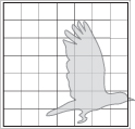
Table 3.1 summarizes the elements, relations, and properties that can appear in C&C views. It is followed by a more detailed discussion of these concepts, together with guidelines concerning their documentation.
Table 3.1 Summary of C&C views
3.2.1 Elements
The elements of a C&C view are components and connectors. Each element in a C&C view of a system has a runtime manifestation, consuming execution resources and contributing to the execution behavior of that system. Attachment relations of a C&C view associate components with connectors (via their respective ports and roles) to form a graph that represents a runtime system configuration.
Components
Components represent the principal computational elements and data stores that are present at runtime. Each component in a C&C view has a name. The name should indicate the intended function of the component. The name also allows you to relate the graphical element with any supporting documentation for that component.
![]()
Components are the principal computational elements and data stores that execute in a system.
Components have interfaces called ports. A port defines a specific point of potential interaction of a component with its environment. A port usually has an explicit type, which defines the kind of behavior that can take place at that point of interaction. A component may have many ports of the same type. In this respect, ports differ from interfaces of modules, whose interfaces are never replicated. For example, a filter might have several input ports of the same type to handle multiple input streams, or a server might provide a number of request ports for client interactions. The database in Figure 3.1 has two ports for two kinds of access.
![]()
A port is an interface of a component. A port defines a point of interaction of a component with its environment.
You can annotate a port with a number or range of numbers to indicate replication. For example, a port annotated with “[3]” stands for three occurrences of that port. A port annotated with “[0..10]” means that there are from 0 to 10 instances of that port. That form is useful when defining component types, allowing component instances to bind the exact number, or for components that dynamically create new points of interaction.
A component’s ports should be explicitly documented, by showing them in the diagram and defining them in the diagram’s supporting documentation.
![]()
To indicate multiple ports of the same type in a diagram using an informal notation, you can draw each one separately or you can show a single port but append a bracketed number (for example, [5]) after the port’s name to indicate its degree of replication. UML provides a similar convention.
A component in a C&C view may represent a complex subsystem, which itself can be described as a C&C subarchitecture. This subarchitecture can be depicted graphically in situ when the substructure is not too complex, by showing it as nested inside the component that it refines. Often, however, it is documented separately. A component’s subarchitecture may be in a style different from the one in which the component appears.
![]()
See Chapter 7 for a more complete discussion of types of information that can be used to define a port.
Section 6.1 contains more detail on guidelines for documenting hierarchical relationships and refinement.
See Section 3.2.3 for more information on how to document substructure using an interface delegation relation.
When a component has such a substructure, you should also document the relationship between the “internal” and “external” ports. As we describe later, this relationship is captured using an interface delegation relation.
Connectors
Connectors are the other kind of element in a C&C view. Simple examples of connectors are service invocation, asynchronous message queues, event multicast, and pipes that represent asynchronous, order-preserving data streams. But as we noted earlier, connectors often represent much more complex forms of interaction, such as a transaction-oriented communication channel between a database server and a client, or an enterprise service bus that mediates interactions between collections of service users and providers.
![]()
A connector is a runtime pathway of interaction between two or more components.
Connectors have roles, which are its interfaces, defining the ways in which the connector may be used by components to carry out interaction. For example, a client-server connector might have invokes-services and provides-services roles. A pipe might have writer and reader roles. Like component ports, connector roles differ from module interfaces in that they can be replicated, indicating how many components can be involved in its interaction. A publish-subscribe connector might have many instances of the publisher and subscriber roles.
![]()
A role is an interface of a connector. A role defines a point of interaction of a connector and indicates how components may use a connector in interactions.
A role typically defines the expectations of a participant in the interaction. For example, an invokes-services role might require that the service invoker initialize the connection before issuing any service requests. The semantics of the interaction represented by a connector is often documented as a protocol specification prescribing what patterns of events or actions are allowed to take place over the connector.
![]()
A protocol specification or a pattern of events can be described using behavioral notations, described in Chapter 8.
Like components, complex connectors may in turn be decomposed into collections of components and connectors that describe the architectural substructure of those connectors. For example, a decomposition of the failover client-server connector of Figure 3.1 would probably include components that are responsible for buffering client requests, determining when a server has failed, and rerouting requests.
![]()
Refinement is described in Section 6.1.
3.2.2 Component-and-Connector Types and Instances
The components and connectors depicted in a C&C view are instances of component-and-connector types. A type is an incompletely defined component or connector. Type definitions often express a set of choices, such as using a multiplicity indicator like [1..5] to indicate that a component may have from 1 to 5 ports.
![]()
When documenting a C&C view:
• Make clear in the view what architecture style is being used. Refer the reader to the appropriate style guide for more information about the style.
• Document any additional component or connector type specializations introduced in the view.
It is usually not a good idea to mix types and instances in the same diagram.
An instance is the result of completing the definition by binding the choices that the types create. Each instance must conform to its type in terms of behavior, interfaces, substructure (if any), properties, and topological restrictions. As a result of this conformance requirement, all instances of a given type are more or less identical. For example, the type may define a set of allowable behaviors. An instance can restrict this set, perhaps through instantiation parameters, but an instance can’t add behaviors.
A C&C view’s primary presentation depicts only instances; no component or connector types should appear in the view’s primary presentation. Mixing types and instances in the same diagram is generally ill-advised. Although it may seem convenient (“I’ll just add a little inheritance information to clarify a relationship between different instances”), it is more likely to add confusion.
Types are found in style guides. However, type definitions given in style guides, including the ones in this book, are too general to sufficiently constrain an implementation or support useful analysis. It would make no sense to instantiate them as they are without specializing them first. Type definitions like these define the essence of the elements of the style. For example, a style guide for the client-server style will define the component types client and server, define the connector type request/reply connector, and specify how their interfaces differ (for example, that clients make requests of servers, who in turn reply to clients). Such abstract types, however, do not provide any application-specific semantics for the components (for example, whether a server supplies Web pages or processes banking transactions).
Types might specialize more general types in domain-specific ways, such as a controller servlet that takes requests from ATMs in a banking system, or a sensor component type, used in an avionics application. Or they might be technology-specific, such as an ASP.NET component, a Java servlet, an Enterprise JavaBean (EJB), a MySQL database, or a database connector. Like an abstract class in Java, these are usually still too general to drive an implementation or support useful analysis.
Architects need to define application-specific specializations of those types that contain enough information so that instances that populate a view can be implemented and analyzed. We’ll call these application-specific types. Document these types in your view’s supporting documentation. Application-specific types provide application-specific semantics, such as a detailed behavior specification (such as showing how a request is processed) or refined interfaces (such as refining the general notion of a “request” with a specific set of request types). The type definition should also characterize the number of interface types (ports for components, roles for connectors) that instances of the type can have.
![]()
A style is a specialization of another style if it is consistent with that style—that is, doesn’t violate it—and adds more constraints to its element types, relation types, and/or topological restrictions.
![]()
Document application-specific types you introduce in the view’s element catalog, part of a view’s supporting documentation. Element catalogs are discussed in Section 10.1.
Component-and-connector types, whether introduced in style guides or as application-specific specializations, are useful to identify elements with common behavior, interfaces, substructure, relations to implementation elements, and so on. Localizing this information in a type definition (as opposed to replicating it across each instance of an implied type) improves understandability and simplifies the overall documentation.
![]()
This flow from a style’s types to application-specific types to instances constitutes a spectrum of design, which is discussed in Section 6.1.3.
In many cases the use of component-and-connector types allows one to conveniently map a component type (and by extension, all of its instances) to its implementation in a module view. For example, if a set of name-lookup servers in a C&C view are defined as instances of the NameLookupServer type (a specialization of the client-server style’s Server type), one might expect to find a corresponding module that implements the behavior of all instances of such a server. A mapping between some module and the NameLookupServer type would indicate that every instance of the NameLookupServer corresponds to that module.
![]()
Mappings between C&C and module views are discussed in more detail in Section 3.5.
3.2.3 Relations
The primary relation within a C&C view is attachment. Attachments indicate which connectors are attached to which components, thereby defining a system as a graph of components and connectors. Specifically, an attachment is denoted by associating (attaching) a component’s port to a connector’s role.
A valid attachment is one in which the ports and roles are compatible with each other, under the semantic constraints defined by the style. For example, in a call-return architecture, you should confirm that all “calls” ports are attached to some call-return connector. At a deeper semantic level, you should ensure that a port’s protocol is consistent with the behavior expected by the role to which it is attached.
![]()
It is possible to establish an interface delegation between two ports of different types. It is also possible to relate multiple internal ports to a single external port. If you do either of these, make sure to explain what that delegation means and why it’s valid, in the element catalog entry for that view.
A second kind of relation is interface delegation. When a component or connector has a subarchitecture, it is important to document the relationship between the internal structure and the external interfaces of that component or connector. The relationship can be documented using interface delegation relations. Such relations map internal ports to external ports (for components) or internal roles to external roles (for connectors). Some notations provide specific graphical elements to characterize this relationship. Figure 3.2 shows an example of interface delegation in UML notation. UML “delegation connectors” are used to represent interface delegation.
Figure 3.2 A UML component diagram showing the subarchitecture of a component called Catalog. UML delegation connectors associate the ports of Catalog with the ports of internal components.

![]()
Describing C&C views with UML is covered in detail in Section 3.4.3 and Appendix A.
3.2.4 Properties
An element (component or connector) of a C&C view will have various associated properties. Every element should have a name and type. Additional properties depend on the type of component or connector. The properties are needed to guide the implementation and configuration of components and connectors, but the architect should also define values for the properties that support the intended analyses for the particular C&C view. For example, if the view will be used for performance analysis, latencies, queue capacities, and thread priorities may be necessary. The following are examples of some typical properties and their uses:
• Reliability. What is the likelihood of failure for a given component or connector? This property might be used to help determine overall system reliability.
• Performance. What kinds of response time will the component provide under what loads? What kinds of latencies and throughputs can be expected for a given connector? This property can be used with others to determine system properties such as response times, throughput, and buffering needs.
• Resource requirements. What are the processing and storage needs of a component or a connector? This property can be used to determine whether a proposed hardware configuration will be adequate.
• Functionality. What functions does an element perform? This property can be used to reason about overall computation performed by a system.
• Security. Does a component or a connector enforce or provide security features, such as encryption, audit trails, or authentication? This property can be used to determine system security vulnerabilities.
• Concurrency. Does this component execute as a separate process or thread? This property can help to analyze or simulate the performance of concurrent components and identify possible deadlocks.
• Tier. For a tiered topology, what tier does the component reside in? This property helps to define the build and deployment procedures, as well as platform requirements for each tier.
![]()
Tiers are defined and discussed in Section 4.6.2.
Ports and roles also may have properties associated with them. For example, maximum sustainable request rates may be specified for a server port.
Advice
To illustrate what not to do, Figure 3.3 presents an example of a poorly documented C&C view diagram.
Figure 3.3 A poorly documented C&C view diagram. It does not have a key; it portrays an interface (assuming that “API” has the common meaning of an interface) as a component; it uses different shapes for the same type of component; it uses the same shape for different types of components and connectors; it confuses the context with the system to be built; its use of arrows is not explained; and its components do not have ports.

Perspectives: Are Complex Connectors Necessary?
In this book we treat connectors as first-class design elements for documenting runtime-oriented views: Connectors can represent complex abstractions; they have types and interfaces, or roles; and they require detailed semantic documentation. But couldn’t one simply use a mediating component for a complex connector? For example, in Figure 3.4, the complex connector Connector 1 gets replaced by the component Component 1 and two (presumably) simpler connectors. For instance, Connector 1 might be a pipe that implements buffered data flow between components. On the other hand, Component 1 might be a buffer, and Connector 1A and Connector 1B might be simple procedure calls to read or write to the buffer.
Figure 3.4 A complex connector and the alternative of representing it as a component with two simpler connectors

In other words, are complex connectors needed? The answer is yes. Here’s why.
First, complex connectors are rarely realizable as a single mediating component. Although most connector mechanisms do involve runtime infrastructure that carries out the communication, that is not the only thing involved. In addition, a connector implementation requires initialization and finalization code; special treatment in the components that use the connector, such as using certain kinds of libraries; global operating system settings, such as registry entries; and others.
Second, use of complex connector abstractions often supports analysis. For example, reasoning about a data flow system is greatly enhanced if the connectors are pipes rather than procedure calls or another mechanism, because well-understood calculi are available for analyzing the behavior of data flow graphs. Additionally, allowing complex connectors provides a single home where one can talk about their semantics. For example, in Figure 3.4, I could attach a single description of the protocol of interaction to the complex connector. In contrast, the lower model would require me to combine the descriptions of two connectors and a component to explain what is going on.
Third, using complex connectors helps convey an architect’s design intent. When components are used to represent complex connectors, it is often no longer clear which components in a diagram are essential to the application-specific computation and which are part of the mediating communication infrastructure.
Fourth, complex connector abstractions can significantly reduce clutter in an architecture model. Few would argue that the lower of the two diagrams in Figure 3.4 is easier to understand. Magnify this many times in a more complex diagram, and it becomes obvious that clarity is served by using connectors to encapsulate details of interaction.
—D.G.
3.3 What C&C Views Are For
Component-and-connector views are commonly used to show developers and other stakeholders how the system works. The C&C views (with associated behavior documentation) specify the structure and behavior of the runtime elements. In particular, these views allow you to answer questions, such as the following:
• What are the system’s principal executing components, and how do they interact?
• What are the principal shared-data stores?
• Which parts of the system are replicated, and how many times?
• How does data progress through a system as it executes?
• What protocols of interaction are used by communicating entities?
• What parts of the system run in parallel?
• How can the system’s structure change as it executes?
![]()
It’s a good idea to provide comprehensive behavior documentation for each component (or component type). Each such model documents the possible behaviors of a component. When combined with the topological information in a C&C view, you can trace possible behaviors throughout the system, rather than just within a component.
Component-and-connector views are also used to reason about runtime system quality attributes, such as performance, reliability, and availability. In particular, a well-documented view allows architects to predict overall system properties, given estimates or measurements of properties of the individual elements and interactions. For example, to determine whether a system can meet its real-time scheduling requirements, you usually need to know the execution time of each process component (among other things). Timing behavior such as this would be represented as properties of the elements. Similarly, documenting the reliability of individual elements and communication channels supports an architect when estimating or calculating overall system reliability. In some cases, analyses such as these are supported by formal, analytical models and tools. In others, it is achieved by judicious use of rules of thumb and past experience.
Perspectives: Choosing Connector Abstractions
If you’ve committed to a particular C&C style, then the types of connectors to use in documenting a C&C view are already prescribed. But in other cases the architect has some freedom to determine what kinds of connectors to use and how to represent them in documentation. This choice often revolves around how much implementation structure to expose. On the one hand, a connector might be used to encapsulate a complex interaction as a single abstraction. On the other hand, a complex form of interaction can be represented as a set of components and connectors that implement it.
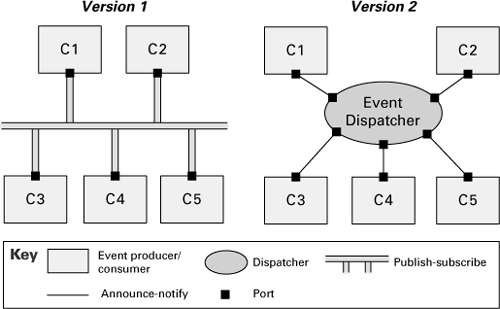
To illustrate, consider two ways of documenting a publish-subscribe system shown in Figure 3.5. The first version shows five components communicating through an event bus, which describes an interaction that ensures that each published event is delivered to all subscribers of that event. The second version shows the same five components communicating with the assistance of a centralized dispatcher component responsible for distributing events via procedure calls to the other components.
Figure 3.5 Two potential versions of a publish-subscribe system. In Version 1, all communication takes place over an event bus; in Version 2, communication occurs with the assistance of a dispatcher component.
![]()
The publish-subscribe style is described in Section 4.4.1.
There are several advantages to using the first approach:
• It simplifies the description, since there are fewer elements in the view.
• It clearly distinguishes the parts of the architecture that are used for interaction (the connectors) and the parts that are used to provide the computational functions of the system (the components).
• It permits a variety of implementations to be used to effect the event-based interactions. For instance, instead of a single dispatcher, there could be several, or alternatively each component could be responsible for sending its events to the required listeners.
• It provides a natural way to decompose documentation into multiple views, where the specific implementation would be represented in its own view as a refinement of the event bus connector.
![]()
Refinement is discussed in Section 6.1.
On the other hand, the second approach has some advantages:
• It clearly indicates what kinds of mechanisms are being used to carry out event announcement.
• It may better support reasoning about runtime properties, such as delays, order guarantees, and so on, where knowledge of the specific mechanisms for dispatch is needed.
• It fits with what your chosen notation allows: For instance, because UML does not provide a way to represent rich connectors, we are forced to adopt the second approach.
Thus the choice of connector abstraction will depend on taste, needs for analysis, and the amount of implementation detail known to the architect when the architecture is documented. In practice, however, documentation usually errs on the side of putting in too much detail, using low-level communication mechanisms and additional components instead of defining the higher-level interaction abstractions that they represent.
—D.G.
3.4 Notations for C&C Views
3.4.1 Informal Notations
As always, box-and-line drawings are available to represent C&C views. Figure 3.1 is an example of a C&C diagram that uses an informal notation (explained in the diagram’s notation key). Although informal notations can convey limited semantics, following some guidelines can lend rigor and depth to the descriptions. The primary guideline is to assign each component type and each connector type a separate visual form (symbol), and to list each of the types in a key.
Beyond just naming the types, however, their meaning should be specified. For example, Figure 3.1 shows a connector of type Publish-Subscribe, but the diagram does not show the connector’s capacity, the type of data it can transmit, whether or not delivery is guaranteed, or a host of other important considerations. These details can be documented in the style guide in which the type is defined, or as properties in the C&C view’s element catalog.
![]()
Element catalogs document the architecture elements that appear in a view. They are discussed in Section 10.1.
Take special care with connectors. A common source of ambiguity in most existing architecture documents is the meaning of connectors, especially ones that use arrows as their visual symbol. Make sure to say what the arrow’s direction means.
![]()
See “Perspectives: Quivering at Arrows” on page 41, in the prologue.
3.4.2 Formal Notations
Most, if not all, architecture description languages (ADLs) can be used to describe component-and-connector types, constraints on topologies of component-and-connector graphs, and properties that can be associated with the elements of the graph. Tools may then process an architecture description by referring to the meanings of the types, the constraints, and the properties. For example, some ADL-associated tools can tell you if a set of processes can be scheduled so that, given the resources of the CPU, they will all meet their processing deadlines.
![]()
Consider the following criteria if selecting an ADL: How standardized is it? What analysis or code generation does it enable? Does it lend itself only to representing certain styles, and if so, are those styles the ones you need for your architecture? Will it let you represent all of the views of the architecture that you need? Is it extensible? How robust are its tools? Is it commercially supported? Is there a large and active user community with whom you can interact?
3.4.3 Semiformal Notations: UML
This section introduces some basic UML modeling constructs for representing components and connectors. Appendix A goes into more depth about using UML to represent other facets of architecture.
Components in UML
UML components are a good semantic match to C&C components because they permit intuitive documentation of important information such as interfaces, properties, and behavioral descriptions. UML components also distinguish between component types and component instances, which is useful when defining view-specific component types.
![]()
Section 3.2.2 discusses types and instances of components and connectors.
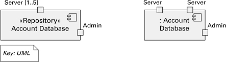
Because C&C components that appear in a view are instances, they should be represented using UML component instances, as shown in Figure 3.6. The visual distinction between UML component types and instances is found in the naming convention. Names that do not include a colon (:) are types; names that include a colon are instances, with the instance name appearing to the left of the colon. Anonymous instances, such as the instance of Account Database in Figure 3.6, are shown by starting the name with a colon.
Figure 3.6 A UML representation of a portion of the C&C view originally presented in Figure 3.1. This fragment only shows how four components are represented in UML. Main and Backup are instances of the same component type (Account Server).

You can define a component type in a UML diagram in a style guide you’re writing or in a view’s element catalog for a view-specific type. You should specify attributes common to all instances on the component type. If creating a view-specific type, you should link the type definition to a type defined in your style guide, such as by placing a stereotype on the type definition, as shown in Figure 3.7.
Figure 3.7 A UML representation of a C&C component type. The Account Server component type is a specialization of the Server component type from the client-server style (see Section 4.3.1).

![]()
The element catalog of an architecture view provides information about the elements in that view. Element catalogs are described in Section 10.1.
UML ports are a good semantic match to C&C ports. A UML port can be decorated with a multiplicity, as shown in the left portion of Figure 3.8, though this is typically done only on component types. The number of ports on component instances, as shown in the right portion of Figure 3.8, is typically bound to a specific number. Components that dynamically create and manage a set of ports should retain a multiplicity descriptor on instance descriptions.
Figure 3.8 A UML representation of the ports on a C&C component type (left) and a component instance (right). The Account Database component type has two types of ports, Server and Admin (denoted by the boxes on the component’s border). The Server port is defined with a multiplicity, meaning that multiple instances of the port are permitted on any corresponding component instance.
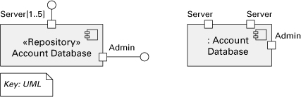
UML provides a lollipop/socket notation for showing provided and/or required interfaces attached to ports. Each port can have an arbitrary number of provided and required interfaces. Figure 3.9 shows the same components in Figure 3.8, but now each port of the Account Database type includes one provided interface (the lollipop), which can be further elaborated in UML by supplying additional information, such as methods or attributes. The instance of Account Database on the right has exactly two Server ports, and the interfaces are omitted.
Figure 3.9 Each port on the Account Database type now includes one supplied interface (the lollipop), which can be further elaborated in UML by supplying additional information, such as methods or attributes. The instance of Account Database on the right has exactly two Server ports, and the interfaces are omitted.
The lollipop/socket notation of UML can be confusing if not used carefully. If the style of connector interaction is some form of call-return, then the lollipop and socket correspond to calls that are provided and required, respectively. In a client-server connector, a single port might provide and require something at the same time, in which case you would adorn the same port with both a lollipop and a socket. But in other cases, where “provides” and “requires” are the wrong intuition, the notation should be avoided. In a pipe-and-filter system, for example, what does a filter interface “provide” and what does it “require?” In that case, just document the port by itself.
Even where appropriate, you normally omit lollipops and sockets from a C&C view (which shows instances) and use them only on the component type definitions. Often, full interface details will be provided with a component type definition, and only ports will be shown in a C&C primary presentation. This reduces visual clutter without losing the instances’ precise interface definitions.
![]()
The primary presentation is the (typically) graphical portion of an architecture view, as described in Chapter 10.
Connectors in UML
While C&C connectors are as semantically rich as C&C components, the same is not true of UML connectors. UML connectors cannot have substructure, attributes, or behavioral descriptions. This makes choosing how to represent C&C connectors more difficult, as UML connectors are not always rich enough.
You should represent a “simple” C&C connector using a UML connector—a straight line. Many commonly used C&C connectors have well-known, application-independent semantics and implementations, such as function calls or data-read operations. If the only information you need to supply is the type of the connector, then a UML connector is adequate. Call-return connectors can be represented by a UML assembly connector, which links a component’s required interface (socket) to the other component’s provided interface (lollipop). You can use a stereotype to denote the type of connector. If all connectors in a primary presentation are of the same type, you can note this once in a comment rather than explicitly on each connector, to reduce visual clutter. Attachment is shown by connecting the endpoints of the connector to the ports of components. Figure 3.10 illustrates some of these points.
Figure 3.10 A UML representation of a “simple” C&C connector between two components. The type of the connector is noted by a stereotype (<<DB Access>> in this case).

Connector roles cannot be explicitly represented with a UML connector because the UML connector element does not allow the inclusion of interfaces (unlike the UML port, which does allow interfaces). The best approximation is to label the connector ends and use these labels to identify role descriptions that must be documented elsewhere.
If you also need to supply simple descriptive information, such as attribute-value pairs, attach it to a UML connector by using tagged values or a comment.
You should represent a “rich” C&C connector using a UML component, or by annotating a straight-line UML connector with a tag or other auxiliary documentation that explains the meaning of the complex connector.
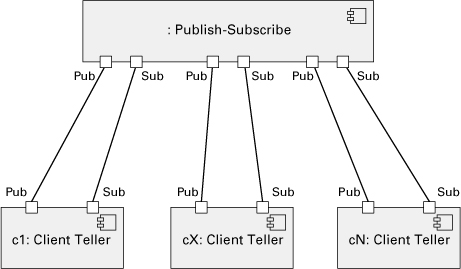
Figure 3.11 shows an example of representing a C&C connector using a UML component. In this approach, roles are represented using UML ports. Attachment relations are represented by attaching the UML ports of the components and the connector using a UML connector. Although it’s not ideal to use the same graphical convention as for a C&C component, it is sometimes necessary in UML.
Figure 3.11 A UML representation of a “rich” C&C connector used to connect three components. The Publish-Subscribe connector is represented using a UML component. Its roles are represented using UML ports. Attachments between C&C ports and roles is represented using UML connectors between the respective UML ports.
Sometimes it is better to use a straight line (possibly stereotyped) with a tag that explains the complex connector. For example, suppose you have ten clients, each of which is talking over the same nontrivial asynchronous protocol to some server. Introducing ten extra components would make for a lot of clutter, when a stereotyped straight-line connector would be at least as clear.
![]()
See “Perspectives: Are Complex Connectors Necessary?” on page 135, in this chapter.
A C&C Primary Presentation in UML
The C&C primary presentation found in Figure 3.11 is an example of a combined view that combines the client-server, publish-subscribe, and shared-data styles presented in Chapter 4. Figures 3.12 and 3.13 show how to represent the same information using UML.
Figure 3.12 A UML representation of component-and-connector types for Figure 3.11. Each type uses a stereotype to link the view-specific subtypes to the types defined in the style guides.

Figure 3.13 A UML representation of the primary presentation found in Figure 3.11

Figure 3.12 defines the component-and-connector subtypes that are view specific. Each type uses a UML stereotype to identify the corresponding component or connector type defined in one of the three cited style guides. Multiplicities are attached to some of the ports to note where multiple connections are permitted and to set bounds on the number of connections. This information should be in the view’s element catalog.
Figure 3.13 shows the view’s primary presentation, as represented using UML. Like the Publish-Subscribe connector, the Failover Request/Reply connector is represented using a UML component; this allows the details of the failover semantics to be formally documented, and it simplifies the representation of an n-ary connector.
In addition to the advice presented on representing basic C&C concepts in UML, we had to decide how to represent the implied variability from Figure 3.11. That figure gives the intuition of a variable number of Client Teller components, any of which may be connected to one or both of the Account Server components at some point in time.
Using a semiformal notation like UML forces us to be more precise about the meaning that was largely implied in the informal version. Representing a variable number of components is not easy using a UML instance diagram. We opted for a naming convention of using Client Teller components c1, cX, and cN to fill in for an arbitrary number of clients (1..N). The meaning of this convention would have to be documented in the view, as it is not a standard UML convention.
UML contains many of the right modeling elements to document C&C components in an intuitive way, but it suffers from visual blandness. Where an informal C&C notation could use different shapes for different component types to highlight important distinctions, all UML component types are graphically depicted using the same rectangular box. UML permits such visual customization in theory, but tool support is lacking. Similarly, different types of connectors cannot be quickly distinguished by, for example, noting different line conventions; instead, the reader must distinguish between textual descriptions on lines or in boxes, which also tends to introduce visual clutter.
Perspectives: Data Flow and Control Flow Models
Two representations that have long been used to document software systems—for so long, in fact, that we might consider them archaic today—are data flow and control flow models. These models show how data and control flow through a system during execution. Remember data flow diagrams from Structured Analysis? They’re an example, and probably the best known example, of a notation for a data flow model. Going back still farther in time, flow charts are a notation for control flow models. Once ubiquitous forms of software documentation, both have receded in usage, but they can still be found in pockets of practice. Many software engineers trained in, for example, data flow diagrams see similar-looking C&C views of architecture and ask “What’s the difference?”
Plenty. First, if the nodes in the diagrams are not architecture elements—pieces of programs, for example—then the diagrams are simply not architectural. But what if the elements shown are architectural elements? Then they can be said to be architecture diagrams, but they are still not full-fledged architecture views. A C&C view would show ports, feature-rich connectors with specified connector protocols, behavioral and interface documentation, mechanisms for variability, and design rationale.
Both data flow models and control flow models can be seen as derivatives of a corresponding C&C view. You can derive a data flow model from a C&C view by examining the connector protocols to determine in which direction data can flow between components, then replacing the C&C connectors that carry data with simple one- or two-headed arrows indicating flow of data and eliminating C&C connectors that don’t carry data. You can take a similar approach to deriving a control flow model.
![]()
The flow chart is a most thoroughly oversold piece of program documentation. . . . The detailed blow-by-blow flow chart . . . is an obsolete nuisance suitable only for initiating beginners into algorithmic thinking.
—Fred Brooks, The Mythical Man-Month (1995)
But why would you? First of all, replacing connectors with arrows isn’t as easy as it sounds; see “Perspectives: Quivering at Arrows” in Section P.5 for a discussion of the difficulties associated with even a simple connector. Now imagine replacing a complex connector with an arrow when that connector involves exception handling, timeouts, callbacks, or multistage negotiated protocols.
![]()
See “Perspectives: Quivering at Arrows” on page 41, in the prologue.
Second, for all but the simplest architectures, it’s hard to imagine you’d want an architecture document to contain the derived models but not their full-fledged C&C view counterparts. Granted, a data flow model or a control model highlights only certain aspects of a view in order to simplify discussion or to focus on specific properties, but those properties can be highlighted in the full view. And keeping them separate means having more documentation to maintain, because it’s unlikely that a tool will keep the view and the derived model consistent with each other; you’ll have to do that manually when either changes.
Third, for most analysis that you’d want to perform using a data flow or control flow model, you’re going to need the information in the full C&C view that those models throw away. For example, control flow diagrams are useful for tracking down bugs in a federation of components. But so are the protocol specifications that dictate how those components interact.
Data flow and control flow models are only architectural if their nodes are architecture elements. But even if they are, they are at best only shadows of full-fledged architecture views. Think carefully before you invest in creating and maintaining them.
—D.G. and P.C.
3.5 Relation to Other Kinds of Views
Component-and-connector views differ from module views in fundamental ways. In particular, the elements of a C&C view represent instances of runtime entities, whereas the elements of a module view represent implementation entities. For example, consider a system that has 10 identical clients connected to a single server. That’s 11 components and 10 connectors—but exactly 2 modules (assuming the simplest mapping between views).
An important consideration is how to relate the C&C and module views of a system. Often, the relationship between a system’s C&C views and its module views may be complex.
• The same code module might be executed by many of the elements of a C&C view.
• A single component of a C&C view might execute code defined by many modules.
• A C&C component might have many points of interaction with its environment, each defined by the same module interface.
• Since not every module is necessarily shown in every module view, a component in a C&C view may not map to any module in a particular module view at all.
Figure 3.14 shows both a module view and a C&C view of the same system:
• The module view represents a typical implementation that one might find using the C programming language. In this view, the relation between modules is uses, as described in Chapter 2. The module main starts things off, using the facilities of four modules—To-upper, To-lower, Split, and Merge—that do the bulk of the work. The main module determines how inputs from one are fed to others, using a configuration module, Config. To-upper, To-lower, Split, and Merge use a standard I/O library (stdio) to carry out the communication. Note that from a code perspective, those worker modules do not directly use the services of one another, but rather do so via the I/O library.
• The C&C view shows the same system described in the pipe-and-filter style. Each of the components is a filter that transforms character streams. Pathways of communication between the components are explicit, indicating that during runtime, the pipe connectors will mediate communication of data streams among those components.
Figure 3.14 Component-and-connector and module views of a simple system that accepts a stream of characters as input and produces a new stream of characters identical to the original but with uppercase and lowercase characters alternating

![]()
The pipe-and-filter style is described in Section 4.2.1.
The mapping between these two views is illustrated in Table 3.2. It shows which modules contribute to the implementation of which C&C elements. As you can see, there is an m-to-n relationship for many of the elements of each view.
Table 3.2 Mapping between module and C&C views for the example in Figure 3.14

![]()
The correspondence between the elements in a system’s module views and the elements in its C&C views should be documented as part of the documentation that applies to more than one view. This mapping between views is described in Section 10.2.
In many situations, however, module and C&C views have a more straightforward relationship. Indeed, systems that have natural correspondences between these two kinds of views are often much easier to understand, maintain, and extend. Here are two examples:
• Each component has a type that can be associated with an implementation module, such as a class. In this case the name of the component type will typically be taken to be the same as the corresponding module, making it trivial to relate the two views.
• Each module has a single runtime component associated with it, and the connectors are restricted to calls procedure connectors. This would be the case for an object-oriented implementation in which each class has a single instance.
In addition to relations between C&C views and module views, there is often a close correspondence between C&C views and deployment views. Because C&C views represent runtime elements, it is useful to relate these elements to the physical platforms and communication channels on which they execute using an allocation view.
![]()
Deployment views are discussed in Section 5.2.
3.6 Summary Checklist
• Component-and-connector views describe structures consisting of elements that have runtime presence, such as processes, objects, clients, servers, and data stores. Additionally, C&C views include as elements the pathways of interaction, such as communication links and protocols, information flows, and access to shared storage.
• Component-and-connector views show instances, not types. Style-specific types are defined in a style guide; application-specific types are described in the view documentation.
• Components have interfaces, which are called ports.
• Connectors have interfaces, which are called roles.
• Connectors need not be binary: they may have more than two roles.
• If a component’s primary purpose is to mediate interaction between a set of components, consider representing it as a connector instead.
• Connectors can, and often do, represent complex forms of interaction. What seems to be a semantically simple procedure call can be complex when carried out in a distributed setting, involving runtime protocols for time-outs, error handling, and locating the service provider.
• Be clear about which style you are using, by referring to an appropriate style guide.
• Where helpful, define component-and-connector types specific to the view as specializations of the types defined in the corresponding C&C style. These can help indicate semantic relations between similar components, and to establish correspondence between the module types that implement their functionality.
• Always show a component’s ports explicitly. Always attach a connector to a port of a component, not directly to a component.
• If it is not clear that it is valid to attach a given port with a given role, provide a justification in the rationale section for the view or mark the attachment to be revisited later.
• Make clear which ports are used to connect the system to its external environment.
• Data flow and control flow models are best thought of as projections of C&C views, but they are not views. When creating such models, be explicit about the semantic criteria used to determine where the arrows go. Data flow and control flow arrows are at best approximations to the connectors, which define more completely the components’ interactions.
• It is often important to understand the mapping between components in a C&C view and their respective implementation units in module views. In general, this mapping is many-to-many.
• You can document a C&C style using a spectrum of formality, from informal box-and-line depictions to fully formal, analyzable descriptions. UML is an example of a semiformal notation for representing C&C styles.
3.7 Discussion Questions
1. It is said that a C&C view illustrates a system in execution. Does this mean that it shows a snapshot of an execution, a trace of an execution, the union of all possible traces, some combination, or something else?
2. As we have mentioned, component is an overloaded term. Discuss the relationship between a component in a C&C view and (a) a UML component and (b) a component in the sense of the component-based software engineering community.
3. A communication framework, such as enterprise service bus (ESB), CORBA, or COM, can be viewed as a connector among components or as a component with its own substructure. Which is appropriate, and why?
4. Figure 3.15 shows an overview architecture diagram for an electronic commerce store. Assume that you are new on the job, without knowledge of the symbology the organization uses, or perhaps you wrote this some time ago but now have to go back and review the system. Critique the diagram. List places where you think it is misleading, and list the questions that need to be asked—and that the diagram fails to answer—before you can understand its meaning.
Figure 3.15 An overview architecture diagram. Where is it misleading? What questions does the diagram fail to answer?

5. After you have critiqued Figure 3.15 and have enumerated the information you believe is missing, augment the diagram to make it tell a coherent story. Did you decide that the diagram is describing code-based entities, runtime entities, or both? Did you decide that the boxes called layers are, in fact, layers, or something else? What did you decide the arrows mean?
3.8 For Further Reading
We are awash in stories of architects who thought they could plug two components together with a connector, only to find out that the component didn’t implement the right protocol, or was otherwise badly matched with the expectations of that connector. This is why we prescribe writing a justification where the matchup is less than obvious. For a thoughtful treatment of element mismatch, see the paper by Garlan, Allen, and Ockerbloom (1995).
It is tempting to treat architecture simply as an assembly of components, but there are great conceptual advantages to be gained from elevating connectors to the status of first-class architecture. Mary Shaw (1996b) makes an eloquent argument for doing so. Shaw and Garlan (1996) treat software architecture in terms of components and connectors and address concerns such as constructing systems as assemblies of components. Allen and Garlan (1997) lay out the semantic foundations for connectors as first-class entities.
Component-and-connector views can provide a basis for formal analysis of qualities such as performance, reliability, security, and privacy. Garlan and Schmerl (2006) provide a broad introduction to such analyses.
A swarm of architecture description languages were created in the 1990s. Medvidovic and Taylor (1997) give a tour of them and compare members of that generation. Today only a small number deserve mention. Acme is of that earlier generation (see www.cs.cmu.edu/~acme [Acme 2009]). The Architecture Analysis and Design Language (AADL) is a direct descendant of one from that generation. Appendix C gives an architecture-oriented overview of AADL, and the Web site at aadl.info offers full coverage. Yahoo! Pipes can be considered an ADL, albeit a very style-specific one; see pipes.yahoo.com/pipes (Yahoo! 2010) and the Yahoo! Pipes example in Chapter 4.