7. Documenting Software Interfaces

In this chapter, we look at these aspects of interface documentation:
• Standard organization
• Stakeholders
• Conveying syntactic information
• Conveying semantic information
• Examples of interface documentation
7.1 Overview
So far we have emphasized documenting architecture elements and their relations using various kinds of views. More implicitly than explicitly, we have stated that of course all those elements have interfaces through which they can interact with each other. Interfaces are supremely architectural, for without them one cannot perform analyses or system building—both activities we want to do with an architecture. Therefore, a critical part of documenting a view includes documenting the interfaces of the elements shown in that view.
![]()
An interface is a boundary across which two elements meet and interact or communicate with each other.
Modules, as discussed in Chapters 1 and 2, clearly have interfaces. As we said in Chapter 3, components also have interfaces, but they are often called ports. In this chapter, we will not distinguish between module interfaces and component interfaces; the way you document them is the same.
![]()
An interface document is a specification of what an architect chooses to make publicly known about an element in order for other entities to interact or communicate with it.
Describing an element’s interface means making statements about what other elements can depend on when using this element. Designing an interface means deciding (and documenting with an interface document) which services and properties should be externally visible and which should not. Everything that is externally visible becomes a contract, a promise to users that the element indeed will fulfill its obligations. This on the other hand also means that every implementation of the element that does not violate the contract is a valid one.
![]()
An element’s actors are the other elements, users, or systems with which it interacts.
An element is used by actors. Actors are other elements, either internal or external to the system documented, that interact with an element through its interface. Those interactions can take a variety of forms, such as function or method calls, Web service requests, remote procedure calls, data streams, shared memory, and message passing. Most involve the transfer of control and/or data. These points of interaction with an element are called resources. Thus, an interface consists of one or more resources available for consumption by actors. If the element that provides that interface is a class, the resources are typically called methods.
![]()
A resource of an interface represents a function, method, data stream, global variable, message end point, event trigger, or any addressable facility within that interface.
An interaction extends beyond functionality and state changes. For example, if element A calls element B, the amount of time that B takes before returning control to A is part of B’s interface because it may affect A’s behavior.
Let’s establish some principles about interfaces.
• All elements have interfaces. All software elements described in any view interact with their environment. The architect decides which aspects of the element’s interfaces need to be documented.
• An element’s interface is separate from its implementation. This principle is particularly useful when we want multiple implementations of an element (such as platform-specific implementations) that provide the same interface.
• An element can have multiple interfaces. Each interface contains a separate collection of resources that have a related logical purpose, or represent a role that the element could fill, and each collection serves a different class of actors. Multiple interfaces provide a separation of concerns. A specific actor might require only a subset of the resources provided. If the element has multiple interfaces, this subset of resources should be provided by one of the interfaces. Conversely, the provider of an element may want to grant actors different access rights, such as read or write, to prevent resource contention or to implement a security policy. Multiple interfaces support different levels of access.
Multiple interfaces also support the evolution of elements that are publicly available or used by a large number of actors. If the element’s interface changes, it may not be feasible to modify everything that uses the old version. So you can support evolution by keeping the old interface and adding a new one.
• Elements not only provide interfaces but also require interfaces. An element interacts with its environment by making use of resources or assuming that its environment behaves in a certain way. Without these required resources, the element cannot function correctly. For example, an element may require Internet connectivity. In this case the element would specify that an actor can use a certain resource it provides only if Internet connectivity is present. Otherwise some error indication will be delivered.
![]()
See “Coming to Terms: Provided vs. Required Interfaces” on page 264, in this chapter.
• Multiple actors may interact with an element through its interface at the same time. Some interfaces don’t allow multiple concurrent interactions because of synchronization and multi-threading issues. These restrictions can be made clear by specifying the number of actors that can interact with an element via a particular interface at the same time.
• Interfaces can be extended by generalization. Many times, several interfaces you are designing will include a common set of resources. These resources can be placed in a separate interface, and by using a generalization relation, you are indicating that children interfaces contain (and may extend) the common resources. Examples of resources often shared by several interfaces include the following:
– An initialization operation
– A set of exception conditions, such as failing to have called the initialization operation
– A standard way to handle exceptions, such as invoking a named error handler
– A standard statement of semantics, such as persistence of stored information
• Sometimes it’s useful to distinguish interface types from interface instances in the architecture. Some components can provide multiple instances of the same interface. Consider for example a component that is an observer in the observer design pattern. This component provides an interface with an operation to be called when an observable component sends a change notification. Thus far we have the interface type. If the component is an observer of multiple different observable components, then it may be useful to represent that in the architecture using multiple instances of the observer interface type.
Coming to Terms: Provided vs. Required Interfaces
Architecture elements provide services to other elements through one or more interfaces. This concept of an element and its interface is one of the enduring bedrock concepts of software engineering. But architecture elements can, and often do, need specific services from other elements in order to function correctly. To capture this need, architects can document a required interface.
The information you need to document about what your architecture element requires is the same as what you should document for what it provides: resources, their syntax and semantics, their error-handling behavior, their quality attribute characteristics, and any variation points they provide. In short, you can use the template given in Figure 7.5, later in this chapter, for documenting an interface that your element provides and (separately) an interface that your element requires. You can even fill in the section on rationale and design issues to record your decision-making process for why your element needs what it needs.
![]()
You can use the same template to document a required interface and a provided interface. The documentation of a required interface may become the documentation of a provided interface once the element that provides it is designed or implemented.
Suppose another element provides just the resources you need, or at least resources that are close enough to what you need that you can use them successfully. Would you document a required interface for your element then? Probably not, opting instead to refer to the other element’s provided interface, to say essentially, “I need that.”
But suppose no other element provides the resources your element needs. Maybe there will be one, but its designers are not as far along as you. In that case, it makes much more sense for you to document a required interface for your element, to guide the forthcoming development. Once the element that will provide the interface is designed, your required interface documentation may become the documentation of the new element’s provided interface. When the providing element exists but you think its interface is likely to change substantially over time, or if you think that the element itself might become unavailable, then documenting your required interface also makes good sense. It can then be used to guide and constrain the evolution of the other element’s provided interface, or to shop for and qualify potential replacement elements. Documenting an element’s required interfaces also makes that element’s reusability much easier to judge, because you can immediately see what resources it would expect to find should it be moved to a new environment.
Like all architecture documentation, a required interface can be documented to the degree of specificity needed to do the job. You might sketch out some resources and trust the designers of the providing element to fill in the details, to which you can then adapt your element.
Linking up required and provided interfaces (using, for example, UML’s socket-and-lollipop notation) can give confidence that in a system build, every element has what it needs to work correctly. In UML a socket-and-lollipop pair symbolizes that the interfaces are “compatible,” meaning at least that the provided interface supports a superset of the operations and signals specified in the required interface. That doesn’t tell you if the requiring element uses all resources on the provider’s interface, or only one or two.
7.2 Interface Documentation
Although an interface comprises all aspects of the interaction an element has with its environment, what we choose to disclose about an interface—that is, what we document in an interface’s documentation—is more limited. Writing down every aspect of every possible interaction is not practical and almost never desirable. Rather, you should expose only what users of an interface need to know in order to interact with it. Put another way, you choose what information is permissible and appropriate for people to assume about the element.
The interface documentation tells what other developers need to know about an interface in order to use it in combination with other elements. Note that a developer might observe element properties that are an artifact of how the element is implemented but that are not in the interface documentation. Because these are not in the interface documentation, they are subject to change, and developers use them at their own risk.
Also recognize that different people need to know different kinds of information about the interface. You may have to provide separate sections in the interface documentation to accommodate different stakeholders of the interface.
![]()
Section 10.1 provides a documentation template for views, which has a section reserved for documenting element interfaces.
Interfaces are documented as part of a view. When a given interface occurs in more than one view, choose one to hold the interface documentation and refer to it in the other. Alternatively, package the interface documentation separately and have all views point to it.
Sometimes interfaces in different views have a direct correspondence but are not exactly the same. For example, the interface of a module in a module view often corresponds directly to the interface of a component in a component-and-connector (C&C) view. In many cases, the module and the C&C interfaces are identical, and documenting them in both places would produce needless duplication. In that case, you should document the interface in the view where the documentation will be more useful and make the other view refer to it. For example, a programmatic interface that offers procedure calls as resources will be most useful for implementers, and they are likely to look for the documentation in module views. On the other hand, an interface that corresponds to a message end point in a system using asynchronous messaging is probably more relevant in a C&C view that describes the runtime interactions, queue capacities, and overall throughput.
In other cases, a module and a C&C interface map to each other but are not identical. For example, a module view of a service-oriented architecture (SOA) system may show a Java class that provides an interface with five different operations. Two of these operations correspond to the interface of a SOAP Web service that is depicted in the C&C SOA view of the same system. The other three operations correspond to the interface of a REST Web service that is provided by a different component in the C&C SOA view. Each of the two Web service interfaces corresponds to only part of the module interface. In addition, the Web service interfaces may expose properties (such as availability or response time) not relevant in the module view. The syntax of the resources and data types may also differ due to the translation from the module implementation language (Java) to the language of the Web service interface (XML). In cases like this, you should document the interfaces separately but also record the mapping between them.
![]()
Section 10.2.1 describes how to document the mapping between views, which can contain the mapping between interfaces from different views.
Advice: Guidelines for Documenting an Interface
• Focus on how elements interact with their environments, not on how elements are implemented. Restrict the documentation to effects that are externally visible.
• Expose only what users of the interface need to know. Including a piece of information in the documentation is an implicit promise that the information is reliable and stable. Once information is exposed, other elements may rely on it, and changes will have a more widespread effect.
• Keep in mind who will be using the interface documentation and what types of information they will need. Avoid documenting more than is necessary. For example, you probably need less detail in the interface documentation of a module used only by another developer on the team than you need for an interface that is part of a commercially available API. This chapter presents the “maximum” approach, that is, a fully documented interface. Depending on the importance of the interface, you should decrease the amount of information and the effort spent in the interface documentation.
![]()
See “Coming to Terms: Signature, Interface, API” on page 280, in this chapter.
• When a given interface occurs in multiple views, document it in one view and refer to it in the other, or document the interface separately and make the views point to this interface documentation.
• An interface in a module view and its equivalent counterpart in a C&C view should be documented more extensively only in the view where the documentation will be more useful to the stakeholders. When interfaces in different views map to each other but are not identical, you should document them separately and document the mapping as well.
• Be as specific and as precise as you can, remembering that interface documentation that can be interpreted differently by various parties is likely to cause problems and confusion.
An interface may or may not have an identity of its own. In the simplest situation, an element A provides a single interface that is not provided by any other element. This interface is implicitly associated with element A and doesn’t need a name—it’s the interface of A. Documenting the interface of A is part of documenting element A. In another situation, an element provides two or more different interfaces. Then it’s probably a good idea to identify the interfaces, as I1 or I2 for example, and document them separately. There’s also the situation of a single interface that is provided by two or more elements. In that case, the interface should have an identity so that elements can refer to it, and the interface should be documented independently from the elements.
As in all architecture documentation, the amount of information conveyed in the interface documentation may vary, depending on the importance of the interface and on the stage of the design process when the documentation is updated.
• Early in the design process, the interface might be scarcely specified; for example, an order tracking module provides an operation to locate an order.
• Later, when the responsibilities of the elements become stable, the interface documentation is more fully elaborated; for example, the order-tracking module provides the method locateOrder(orderId) with some description about its semantics.
• Some time later, you may even refine the interface documentation with the final syntax for the method: OrderBean locateOrderById(long orderId).
7.2.1 Showing the Existence of Interfaces in Diagrams
The existence of interfaces can be shown in the primary presentations by using most graphical notations available for architecture. Figure 7.1 shows an example using an informal notation.
Figure 7.1 Graphical notations for interfaces typically show a symbol on the boundary of the icon for an element. Lines connecting interface symbols denote that the interface exists between the connected elements. Graphical notations like this can show only the existence of an interface, not its definition. (a) An element with multiple interfaces. For elements with a single interface, the interface symbol is often omitted. (b) Multiple actors at an interface. Internal client and External client both interact with Transaction Authorizer via the same interface. This interface is provided by Transaction Authorizer and required by both Internal client and External client.

The existence of an interface can be implied even without using an explicit symbol for it. If there is a relation going from element A to B and the relation type involves an interaction,1 that implies that the interaction takes place through the interface of element B.
Figure 7.2 illustrates how interfaces are shown in UML. A provided interface is depicted as a lollipop, and the socket symbol is used for required interfaces (Figure 7.2(a)). Although it shows the existence of an interface, the lollipop symbol reveals little about the definition of an interface. UML interfaces can be connected to classes, components, and packages.
Figure 7.2 UML uses a lollipop to denote a provided interface, which can be appended to classes, components, and packages. Required interfaces are represented with the socket symbol, which is also appended to classes and other types of elements. UML also allows a class symbol to be stereotyped as an interface; a dashed line with a closed, hollow arrowhead shows that an element realizes an interface. The operations compartment of the class symbol can be annotated with the interface’s signature information: method names, arguments and argument types, and so on. Thus the diagram in (a) is equivalent to (b) in this figure.

Sometimes interfaces are depicted by themselves, with or without an associated element. In UML, you can do that by using the classifier box with the <<interface>> stereotype instead of the lollipop. This alternative is particularly useful when multiple elements implement the same interface. Another benefit is that the resources of the interface can be listed in the operations compartment. Figure 7.2(b) shows the provided and required interfaces of class Garage Door as two separate boxes.
When the diagram shows a module using an independent interface, it indicates that any element implementing the interface can be used. This is a useful means of expressing a particular kind of variability: the ability to substitute realizing elements, as shown in Figure 7.3.
Figure 7.3 An interface can be shown separately from any element that realizes it, thus emphasizing the interchangeability of element implementations. OrderDao (and other classes not shown) require an object that implements a database connection, which is represented by the Connection interface. Many elements realize this interface, representing the interchangeable alternatives of database connection implementations.

Advice: Multiple Interfaces
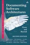
Elements having multiple interfaces raise some subtle design issues and some important documentation issues. If an element interacts with more than one actor, it’s usually best to show interfaces explicitly in your diagrams. If you don’t, a diagram such as Figure 7.4(a) can be ambiguous: Does E have one interface or two? Showing the interface symbol, as in Figure 7.4(b) or (c), resolves the ambiguity.
Figure 7.4 (a) Does element E have one interface or two? This diagram makes it difficult to determine at a glance. (b) By using the interface symbol, it’s clear that this element has one interface and that (c) this element has two interfaces.
7.3 A Standard Organization for Interface Documentation
Remember that an important principle for sound documentation prescribes using a standard organization. A standard organization lets you fill in what you know about an interface now and indicate “TBD” for what you don’t yet know, thus providing a to-do list for the remaining work. This section suggests a standard organization (that is, a template) for interface documentation (see Figure 7.5).
Figure 7.5 Template for interface documentation

![]()
Like all templates in this book, you may wish to modify the one presented in this section to remove items not relevant to your situation or to add items unique to your business. More important than which standard organization you use is the practice of using one.
The standard organization can be used to document each interface of an architecture element. It consists of the following sections:
1. Interface Identity. When an element has multiple interfaces or when the same interface is provided by multiple elements, name the interface. In other cases the identity of the interface is the same as the identity of the element it’s associated with. Some programming languages, such as C# and Java, or frameworks, such as COM, even allow these names to be carried through into the implementation. In some cases merely naming an interface is not sufficient, and the version of the interface must be specified as well. For example, in a framework with named interfaces that have evolved over time, it could be very important to know whether you mean v1.2 or v3.0 of the persistence interface.
2. Resources. The heart of an interface document is the set of resources provided to its actors. Resources are often operations (such as methods, procedures, and functions), but in a more general notion of interface they can be other things, such as data streams, shared data, and messaging end points. In this section you should list the resources and, for each resource, describe the following:
– Resource Syntax. This is the resource’s signature, which includes any information needed to write a syntactically correct program that uses the resource. The signature includes the name of the resource, names and data types of arguments, if any, structure or data type of return values, if any, and so forth.
– Resource Semantics. What is the result of using this resource? What does the resource do from the perspective of the actor invoking it? Semantics come in a variety of guises, including:
i. Assignment of values to the parameters and returned values, including their purpose and semantics. The value assignment might be as simple as setting the value of a return argument or as far-reaching as updating a database table.
ii. Changes in the element’s externally visible state brought about by using the resource. For example, invoking a resource called open() on interface IConnection may change the state of the connection to enable it to start exchanging data. Are these changes persistent or transient? If transient, what is the duration or termination condition?
iii. Events that will be signaled or messages that will be sent as a result of using the resource.
iv. The side effects on other environmental elements as the result of using this resource. For example, if you ask a resource to destroy an object, trying to access that object in the future through other resources will produce quite a different outcome—an error—as a result.
v. Humanly observable results. For example, calling a program that turns on a display in a cockpit has a very observable effect: the display comes on.
![]()
Consider using preconditions and postconditions for documenting resource usage restrictions and resource semantics. A precondition states what must be true before the interaction is permitted; a postcondition describes any state changes resulting from the interaction.
vi. Whether the execution of the resource will be atomic or may be suspended or interrupted, and whether the interaction is synchronous or asynchronous, if such a distinction is applicable.
vii. Usage restrictions. Under what circumstances may this resource be used? Perhaps data must be initialized before it can be read, or perhaps a particular method cannot be invoked unless another is invoked first. Perhaps there is a limit on the number of actors that can interact via this resource at any instant. Perhaps there is a limit of one actor that has ownership and is able to modify the element, whereas others have only read access. Perhaps the resource is thread safe; that is, it can be invoked simultaneously by multiple actors. Perhaps the resource can be invoked only when the authenticated user belongs to a certain group or has certain access rights. Some restrictions are less prohibitive; for example, Java interfaces can list certain methods as deprecated, meaning that users should not use them, as they will likely be unsupported in future versions of the interface. Usage restrictions are sometimes documented by defining exceptions that will be raised if the restrictions are violated.
![]()
See “Coming to Terms: Error Handling” on page 277, in this chapter.
– Error Handling. Describe error conditions and exceptions that can be raised by the resource.
3. Data Types and Constants. Sometimes we need to create new data types (such as records, structs, classes, enumerations, or unions) for the data passed to or returned by resources in the interface. These data types may be defined in the scope of the interface and should be described in the interface documentation. For example, in an airline reservation system, interface IReservation may provide a resource makeReservation() that returns a new data type ReservationRecord. This new data type described in the interface documentation may contain flight number, departure date and time, seat assignment, class, fare, and other data elements. If the data type is defined by another element, a reference to the definition in that element’s documentation is sufficient. In any case, programmers writing elements using such a resource need to know (a) how to declare and assign values to variables of the data type, (b) what operations and comparisons may be performed on members of the data type, and (c) how to convert values of the data type into other data types, where appropriate.
Likewise, new constants are sometimes created in interfaces to hold commonly used values and make programming against the interface more convenient. For example, interface Sequencer of the Java sound API has an operation setLoopCount(int count) to set the number of repetitions of the loop for playback on a MIDI device. For convenience, the interface defines a constant called LOOP_CONTINUOUSLY that can be passed as an argument to that operation.
4. Error Handling. Often you may want to use an error-handling behavior that is common to all or many resources. In that case, you can use this section to describe common error-handling behavior instead of repeating the behavior for every resource in section 2.
Advice
For documenting the error handling for resources in either section 2 or section 4 of interface documentation, do the following:
• If only a few resources have error handling, describe it in section 2.
• If most of the resources follow a common error-handling procedure, describe it in section 4.
• If most of the resources follow a common error-handling procedure but there are resource-specific variations, such as error codes, describe the variations in section 2 and the error-handling procedure in section 4.
• If you are using an error-handling procedure that is common for the whole system, describe the procedure in the rationale section of the “beyond views” part of the documentation (see Section 10.2). Resource-specific information, such as error codes, still needs to be documented with the resource.
![]()
Chapter 10 presents a standard organization for documenting architecture views and the “beyond views” part of the architecture documentation, where you find sections for capturing rationale.
When describing error handling, keep in mind that there are different kinds of errors. An architecture-oriented classification of exceptions is summarized in Figure 7.6. In the context of an element’s interface, exception conditions are one of the following:
1. Errors on the part of an actor invoking the resource.
a. An actor sent incorrect or illegal information to the resource, perhaps calling a method with a null value parameter that should not be null. Associating an error condition with the resource is the prudent thing to do.
b. The element is in the wrong state for the requested resource. The element entered the improper state as a result of a previous action or lack of a previous action on the part of an actor. An example of the latter is invoking a resource before the element’s initialization method has been called.
2. Software or hardware events that result in a violation in the element’s assumptions about its environment.
a. A hardware or software error occurred that prevented the element from successfully executing. Processor failures, network not responding, and inability to allocate more memory are examples of this kind of error condition.
b. The element is in the wrong state for the requested resource. The element’s improper state was brought about by an event that occurred in the environment of the element, outside the control of the actor requesting the resource. An example is trying to read from a sensor or write to a storage device that has been taken off-line by the system’s human operator.
Figure 7.6 A classification of exceptions associated with a resource on an element’s interface

5. Variability. Does the interface allow the element to be configured in some way? These configuration parameters and how they affect the semantics of the interactions in the interface must be documented. Examples of variability include capacities—such as of visible data structures—that can be easily changed. Name and provide a range of values for each configuration parameter, and specify the time when its actual value is bound.
![]()
Variability is discussed in detail in Section 6.4.
6. Quality Attribute Characteristics. You need to document what quality attribute characteristics, such as performance or reliability, the interface makes known to the element’s users. This information may be in the form of constraints on implementations of elements that will realize the interface. The qualities you choose to concentrate on and make promises about will depend on the context. If you’re developing an SOA application where services will be available to external service users, a service-level agreement (SLA) may be required. The SLA specifies quality properties for the entire service or specific operations in the service interface. For example, it may specify that certain operations should provide a specific response time, availability level, and capacity in terms of number of concurrent requests.
7. Rationale and Design Issues. Like rationale for the architecture or architecture views at large, you should also record the reasons behind the design of an element’s interface. The rationale should explain the motivation behind the design, constraints and compromises, alternative designs that were considered and rejected and why, and any insight the architect has about how to change the interface in the future.
8. Usage Guide. Section 2 documents the syntax and semantics on a per-resource basis. This sometimes falls short of what is needed. In many cases, it’s helpful to complement that information with examples that show the usage protocol for one or more resources of the interface. Code snippets are common in the usage guide, but sequence diagrams and other behavioral diagrams are also good choices, especially when a certain sequence of steps for the resource usage is required. Try to craft some clear and simple examples of the most common ways the interface might be used.
![]()
Behavior documentation is covered in Chapter 8.
7.4 Stakeholders of Interface Documentation
In the prologue, we talked about stakeholders having special needs and expectations of an architecture. Some of the stakeholders of interface documentation and the kinds of information they require are as follows:
• Developer of an element, who needs the most comprehensive documentation of the interface the element provides. The developer needs to see any assertions about the interface that he or she will realize in the code. A special kind of developer is the maintainer, who makes assigned changes to the element and its interface.
• Tester of an element, who needs detailed information about all the resources and functionality provided by an interface. The tester can test only to the degree of knowledge embodied in the interface description. If required behavior for a resource is not specified, the tester will not know to test for it, and the element may fail to do its job.
• Developer using an interface, who needs detailed information about the resources provided in the interface to implement elements that will use it. A special case is the integrator, who puts the system together from its constituent elements and has a stronger interest in the behavior of the resulting assembly. In a software product-line context, this stakeholder exploits the variability available in the elements to build different products.
• Analyst, whose information needs depend on the types of analyses conducted. For a performance analyst, for example, the interface document should give information that can feed a performance model, such as execution time required by resources.
• Architect looking for assets to reuse in a new system, who often starts by examining the interfaces of elements from a previous system. The architect may also look in the commercial marketplace to find off-the-shelf elements that can be purchased and do the job. To see whether an element is a candidate, the architect is interested in the capabilities of the interface resources, their quality attributes, and any variability that the element provides.
• Project manager, who is likely to use interface documents for planning purposes. Project managers can apply metrics (such as function-point analysis) to gauge the complexity and then infer estimates for how long it will take to develop an element that realizes the interface. Project managers can also spot special expertise that may be required, and this will assist them in assigning the work to qualified personnel.
7.5 Conveying Syntactic Information
Often architects use a notation they’re familiar with or the notation of the target implementation technology when specifying the syntax of operations in an interface. A very common choice is a C-like syntax, for example:
Order getOrderById(long orderId)
![]()
In the architecture interface documentation, it’s often a good idea to use a syntax that is close to the syntax that will be used in the implementation. However, these days many interfaces are totally or partially implemented using languages that are suitable for automated parsing and processing but may be cumbersome for human readers. XML and JavaScript Object Notation (JSON) are examples. Avoid using these languages in the architecture documentation.
Most programming languages have built-in ways to specify the signature of operations alone. C header (.h) files, and Java and C# interfaces are examples. Some technologies also provide their own syntax for describing the interfaces. The Object Management Group (OMG) Interface Definition Language (IDL) is used in the CORBA technology to specify interfaces’ syntactic information. The Web services technology offers the Web Services Description Language (WSDL). However, WSDL is XML-based and would hardly be considered a good alternative to describe the signature of interface operations.
7.6 Conveying Semantic Information
Natural language is the most widespread notation for conveying semantic information. In many cases, a few sentences suffice to describe what an operation in the interface does and what are the usage restrictions. In other cases, natural language is not enough, and a formal language or notation can prevent future integration errors.
![]()
The example of interface documentation in Section 7.7.1 uses preconditions and postconditions to help explain the semantics of each resource.
A relatively simple and effective method for expressing the semantics of a resource in an interface is to write down its preconditions and postconditions. They can be specified using natural language, but Boolean algebra (that is, first-order logic) is sometimes used to enhance precision.
Traces are also used to convey semantic information by writing down sequences of interactions that describe the element’s response to a specific use.
Semantic information often includes the behavior of an element or one or more of its resources. In that case, notations for behavior, such as sequence diagrams and statecharts, come into play.
![]()
Section 8.5 describes behavior notations such as sequence diagrams and statecharts.
7.7 Examples of Interface Documentation
Following are a couple of examples of interface documentation.
7.7.1 Zip Component API
The interface documentation that follows is for a hypothetical Windows COM component that provides standard zip archive operations. A client application can call the interface to create a zip file and add files to it, extract files from a zip file, list the files inside a zip file, and delete files from a zip file. The example is inspired by publicly available components that offer similar functionality, such as XZip (xstandard.com/en/documentation/xzip).
Sample Interface Documentation
Section 1. Interface Identity
DSAVandBzip: Offers operations to compress, extract, list contents, and delete files from a standard zip file.
Section 2. Resources
![]()
Compress the specified files and folder and add them to the specified zip file. Does not put a file system lock on files when reading them. If the destination zip file doesn’t exist, create it.
• filesToZip: array with the names of the files or folders to be zipped. If an item is a folder, all files and folders inside the folder are zipped recursively.
• zipFile: pathname to the destination zip file that will hold the zipped content.
• savePath: if true, the items in the zip file will keep the original pathname relative to the folder specified in filesToZip; if false, path information will be removed.
• compressionLevel: varies from 1 (minimum compression, but faster to zip and unzip) to 4 (maximum compression, but slower).
Preconditions:
• Files listed in filesToZip exist and are not locked.
• The folder where the specified zipFile is located already exists, the current user has write permission on it, and there is enough disk space.
Postconditions:
• On success, the zip file is created and closed. The original files that were zipped are also closed and remain unchanged.
Possible error codes: 201, 203, 206, 211, 215, 252, 300
![]()
Same as Zip() using the default compressionLevel. See “Section 5. Variability.”
void Unzip(string zipFile, string destFolder, bool overwrite)
Extract and decompress all items inside the specified zip file and save them to the specified destination folder. If a zipped file has a relative path associated to it, the pathname is appended to the destination folder. If the corresponding subfolders don’t exist in the destination, they are created.
Parameters:
• zipFile: pathname to the destination zip file that holds the zipped content.
• destFolder: pathname to the folder where the zipped files will be extracted to.
• overwrite: if true, simply overwrite existing files and folders with the same name in the destination folder.
Preconditions:
• Specified zip file is valid and nonempty.
• The destination folder already exists, the current user has write permission on it, and there is enough disk space.
• The zip file is closed and its contents unchanged. The extracted files are closed at the end and contain the exact content of the original file prior to compression.
Possible error codes: 201, 206, 207, 252, 300
ZipItem[] GetItems(string zipFile)
Get a list of the contents of the specified zip file. Return an array of ZipItem objects in the order they were added to the zip file. Each zip item can be a file or a folder. This operation does not involve decompressing the files.
Parameters:
• zipFile: pathname to the destination zip file that holds the zipped content.
Preconditions:
• Specified zip file is valid and nonempty.
Postconditions:
• The zip file is closed and its contents unchanged.
Possible error codes: 201, 206, 207
long ErrorCode
Global read-only variable that contains the error code of the last operation or zero if the operation was successful. See “Section 4. Error Handling” for more information.
Section 3. Data Types and Constants
• struct ZipItem—represents an item (file or folder) inside a zip file. Attributes:
– string Name: name of the file or folder
– string Path: path to the zipped item
– DateTime Modified: last modified on this date/time
– long OriginalSize: size in bytes of original file
– long CompressedSize: size in bytes of compressed file
– byte Type: indicates whether it’s a file or a folder. Use constants FOLDER and FILE.
• const byte FOLDER = 1
• const byte FILE = 2
Section 4. Error Handling
Upon failure or when certain preconditions are not satisfied, all operations set the ErrorCode global variable. Possible error codes are:
• 203—Cannot create zip file.
• 206—Cannot allocate memory.
• 207—Cannot open zip file.
• 211—Cannot open file/folder to zip.
• 215—Zip file is same as the input file.
• 252—Cannot create files for swapping.
• 254—Unknown error when modifying zip file.
• 300—Disk is full or protected.
Section 5. Variability
• The component may be deployed as a Windows service or as a DLL to be loaded by a caller application.
• Windows registry keys are used for configurable properties, which are read by the component at load time:
– Default compression level
– Whether a log file is created with results of last operations
– Location of the log file
Section 6. Quality Attribute Characteristics
The compression level will affect performance and disk space. If the level is higher, the zip or unzip operation will take longer. However, the operation will require less disk space as the resulting compressed file is smaller. The normal compression ratio obtained at compression level 4 is similar to the ratio obtained using commercial data compression tools, such as WinZip or WinRAR.
Operations that create or update a zip file require disk space for temporary files. The amount of space is not bigger than the size of the zip file.
The execution time of zipping a file is log-linear (n log n) proportional to the size of the file.
The operations in the interface are thread safe and can be called by multiple simultaneous users.
Section 7. Rationale and Design Issues
Different compression levels were created to improve the flexibility for users that require maximum compression ratio versus users that need just a simple and fast compression component.
Section 8. Usage Guide
• Example of calling the component to zip some files:

7.7.2 Interface to a SOAP Web Service
The example software architecture document accompanying this book online contains the architecture documentation for the Adventure Builder application. See wiki.sei.cmu.edu/sad. The OPC Uses View contains the documentation for the OpcPurchaseOrderService and the OpcOrderTrackingService interfaces, which are SOAP-based Web services interfaces.
7.8 Summary Checklist
• All elements have interfaces.
• Many notations for interface documentation show only syntactic information. Make sure to include semantic information as well.
• Elements can have provided interfaces and required interfaces.
• An element can have multiple interfaces and multiple actors at each interface.
• An architect must carefully choose what information to put in interface documentation, striking a balance between usability and modifiability. Put information in an interface document that you are willing to let people rely on. If you don’t want people to rely on a piece of information, don’t include it.
• In graphical depictions, show interfaces explicitly if elements have more than one interface or if you want to emphasize the existence of an interface through which interactions occur. Otherwise, interfaces can be implicit.
• Follow the template given in Figure 7.5 or create your own, making sure to address the needs of the interface documentation’s stakeholders.
7.9 Discussion Questions
1. Think about your favorite Web browser. How many interfaces does it have, and what actors are served by those interfaces?
2. Sketch a picture of the Web browser showing its interfaces and its environment.
3. For one of the interfaces you described in question 1, list a set of exceptions that the browser detects or, from your experience, fails to detect but should.
4. What’s the difference between an interface and a connector?
5. What’s the difference between an interface and a port?
6. Is there a difference between module (as described in Chapter 1) interfaces and component (as described in Chapter 3) interfaces?
7. Why does UML have different symbols for interface and port? In what situation, if any, would you attach an interface to a port of a UML component?
8. Look at an interface description in the Javadoc (or doxygen) documentation for a publicly available library and try to identify the information that corresponds to the information required by the sections of the template presented in Figure 7.5. Is any information missing?
7.10 For Further Reading
An excellent foundation paper on exceptions, which lays the groundwork for separating the concern of detecting an exception from the concern of handling an exception, is the one by Parnas and Wuerges (1976).
Joshua Bloch has delivered at conferences an excellent talk, titled “How to Design a Good API and Why It Matters,” which contains practical guidelines regarding the design and documentation of APIs (Bloch 2006).
Mary Shaw has made the observation that we can’t have complete interface documentation, because the cast of stakeholders is too numerous and the range of information they need is too broad. And in a world in which we get our components from other sources and know precious little about them, good interface documentation is even more rare. However, she points out that we can and do accomplish useful work with such incomplete knowledge. This is so because we can assign confidence measures to individual units of information that we pick up about a component from various sources. She calls such a unit a “credential,” and she assigns it properties such as how we know it and what confidence we have in it (Shaw 1996a, Scaffidi and Shaw 2007).
Interfaces are extremely important in service-oriented solutions in general, and for applications that follow the software as a service (SaaS) model. In SaaS, instead of paying for a software license, customers pay for using the software, which exposes an interface and is available via the Web. In such a scenario, it’s common to provide a service-level agreement. Quality properties that are usually expressed in SLAs, notations for SLAs, and mechanisms to monitor quality of service are discussed in the report by Bianco, Lewis, and Merson (2008).
Viewing interfaces as the set of assumptions that two components are allowed to make about each other dates from early work by Parnas (1971), echoed in later work about architectural mismatch (Garlan, Allen, and Ockerbloom 1995).