
1. Module Views
In this chapter, we look at these aspects of module views:
• Elements, relations, and properties
• Purpose
• Notation
• Relation to other views
1.1 Overview
In this chapter and the next, we look at ways to document the module structures of a system’s software. Such documentation enumerates the principal implementation units, or modules, of a system, together with the relations among these units. We refer to these descriptions as module views. As we will see, these views can be used for each of the purposes outlined in the prologue: education, communication among stakeholders, and the basis for construction and analysis.
The way in which a system’s software is decomposed into manageable units remains one of the important forms of system structure. At a minimum, it determines how a system’s source code is decomposed into units, what kinds of assumptions each unit can make about services provided by other units, and how those units are aggregated into larger ensembles. It also includes global data structures that impact and are impacted by multiple units. Module structures often determine how changes to one part of a system might affect other parts and hence the ability of a system to support modifiability, portability, and reuse.
![]()
The architect must be a prophet . . . a prophet in the true sense of the term . . . if he can’t see at least ten years ahead don’t call him an architect.
—Frank Lloyd Wright
It is unlikely that the documentation of any software architecture can be complete without at least one module view.
We begin by considering module views in the general form. Table 1.1 summarizes the discussion in the following sections about the elements, relations, constraints, and purpose of the module views. In Chapter 2 we provide this information specific to each of a number of often used module styles.
Table 1.1 Summary of the module views

1.2 Elements, Relations, and Properties of Module Views
1.2.1 Elements
System designers use the term module to refer to a wide variety of software structures, including programming language units—such as C programs, Java or C# classes, Delphi units, and PL/SQL stored procedures—or simply general groupings of source code units—such as Java packages or C# namespaces. In this book, we adopt a much broader definition.
![]()
A module is an implementation unit of software that provides a coherent set of responsibilities.
A responsibility is a general statement about an architecture element and what it is expected to contribute to the architecture. This includes the actions that it performs, the knowledge it maintains, the decisions it makes, or the role it plays in achieving the system’s overall quality attributes or functionality.
We characterize a module by enumerating its set of responsibilities, which are foremost among a module’s properties. This broad notion of responsibilities is meant to encompass the kinds of features that a unit of software might provide: that is, its functionality and the knowledge it maintains.
Modules can be aggregated and decomposed. Each of the various module styles identifies a different set of modules and relations, and then aggregates or decomposes these modules based on relevant style criteria. For example, the layered style identifies modules and aggregates them based on an allowed-to-use relation, whereas the generalization style identifies and aggregates modules based on what they have in common.
1.2.2 Relations
Module views have the following types of relations:
• Is part of. The is-part-of relation defines a part/whole relationship between the submodule—the part—and the aggregate module—the whole. In its most general form, the is-part-of relation simply indicates aggregation, with little implied semantics.
![]()
In Chapter 2, the is-part-of relation is refined to a decomposition relation in the decomposition style.
• Depends on. A depends on B defines a dependency relation between A and B. Many different specific forms of dependency can be used in module views. Later, we look at four in particular: uses, allowed to use, crosscuts, and data entity relationships, in the module uses, layered, aspect, and data model styles, respectively. The logical association between classes (in a UML class diagram, for example) also depicts a dependency between the classes.
![]()
In Chapter 2, the depends-on relation is refined to “uses” in the uses style, “allowed to use” in the layered style, and “crosscut” in the aspect style.
• Is a. The is-a relation defines a generalization/specialization relationship between a more specific module—the child—and a more general module—the parent. The child is able to be used in contexts in which the parent is used. Later, we look at this relation in more detail in the generalization style. Object-oriented inheritance and interface realization are special cases of the is-a relation.
![]()
In Chapter 2, the is-a relation is refined to generalization in the generalization style.
1.2.3 Properties
Properties of modules that help to guide implementation or are input to analysis should be recorded as part of the supporting documentation for a module view. The list of properties may vary but is likely to include the following:
• Name. A module’s name is, of course, the primary means to refer to it. A module’s name often suggests something about its role in the system: a module called “account_mgr,” for instance, probably has little to do with numeric simulations of chemical reactions. In addition, a module’s name may reflect its position in a decomposition hierarchy; the name “A.B.C,” for example, refers to a module C that is a submodule of a module B, itself a submodule of A.
• Responsibility. The responsibility property of a module is a way to identify its role in the overall system and establishes an identity for it beyond the name. Whereas a module’s name may suggest its role, a statement of responsibility establishes it with much more certainty. Responsibilities should be described in sufficient detail to make clear to the reader what each module does.
• Visibility of interface(s). When a module has submodules, some interfaces of the submodules may have internal purposes; that is, the interfaces are used only by the submodules within the enclosing parent module. These interfaces are not visible outside that context and therefore do not have a direct relationship to the parent interfaces. Different strategies can be used for those interfaces that have a direct relationship to the parent interfaces. The strategy shown in Figure 1.1(a) is encapsulation. The parent module provides its own interfaces and maps all requests to the capabilities provided by the submodules. The facilities of the enclosed modules are not available outside the parent. Alternatively, the interfaces of an aggregate module can be a subset of the interfaces of its submodules. The aggregate module selectively exposes some of the interfaces of the submodules. Layers and subsystems are often defined in this way. For example, if module C is an aggregate of modules A and B, C’s implicit interface will be a subset of the interfaces of modules A and B (see Figure 1.1(b)).
Figure 1.1 (a) Module C provides its own interface, hiding the interfaces of modules A and B. (b) Module C exposes a subset of the interfaces of modules A and B as its interface.

![]()
Documenting software interfaces is discussed in Chapter 7.
• Implementation information. Because modules are units of implementation, it is useful to record information related to their implementation from the point of view of managing their development and building the system that contains them. Although this information is not, strictly speaking, architectural, it may be useful to record it in the architecture documentation where the module is defined. Implementation information might include
– Mapping to source code units. This identifies the files that constitute the implementation of a module. For example, a module named Account, if implemented in Java, might have several files that constitute its implementation: IAccount.java (an interface), AccountImpl.java (an implementation of Account functionality), AccountBean.java (a class to hold the state of an account in memory), AccountOrmMapping.xml (a file that defines the mapping between AccountBean and a database table—object-relational mapping), and perhaps even a unit test AccountTest.java.
![]()
In addition to identifying the implementation units, one also needs to identify where they reside in a project’s filing scheme: a directory or folder in a file system, a URL in an intranet, or a location in a configuration management system’s storage space. This information is in the purview of the implementation style, discussed in Section 5.5.
– Test information. The module’s test plan, test cases, test scaffolding, and test data are important to store.
– Management information. A manager may need information about the module’s predicted schedule and budget.
– Implementation constraints. In many cases, the architect will have a certain implementation strategy in mind for a module or may know of constraints that the implementation must follow. This information is private to the module and hence will not appear, for example, in the module’s interface.
Module styles may have properties of their own in addition to these. Also, you may find other properties useful that are not listed.
1.3 What Module Views Are For
Expect to use module views for
• Construction. A module view can provide a blueprint for the source code and the data store. In this case, the modules and physical structures, such as source code files and directories, often have a close mapping.
![]()
Section 10.3 discusses documenting the mapping between requirements and architecture.
• Analysis. Two important analysis techniques are requirements traceability and impact analysis. Because modules partition the system, it should be possible to determine how the functional requirements of a system are supported by module responsibilities. Some functional requirements will be met by a sequence of invocations among modules. Documenting such sequences shows how the system is meeting its requirements and identifies any unaddressed requirements. Impact analysis, by contrast, helps to predict the effect of modifying the system. Module views that show dependencies among modules or layers provide a good basis for impact analysis. Modules are modified as a result of problem reports or change requests. Impact analysis requires a certain degree of design completeness and integrity of the module description. In particular, dependency information has to be available and correct in order to create useful results.
• Communication. A module view can be used to explain the system’s functionality to someone not familiar with the system. The various levels of granularity of the module decomposition provide a top-down presentation of the system’s responsibilities and therefore can guide the learning process. For a system whose implementation is already in place, module views, if kept up to date, are very helpful, as they explain the structure of the code base to a new developer on the team—much more effective than providing the URL to the version management system repository and asking him or her to browse the source files and read the code. Thus, up-to-date module views are very useful during system maintenance.
![]()
Expect to use component-and-connector and allocation views, not module views, to analyze performance, reliability, and other runtime qualities.
On the other hand, it is difficult to use the module views to make inferences about runtime behavior, because these views are just a static partition of the functions of the software. Thus, a module view is not typically used for analysis of performance, reliability, or many other runtime qualities. For those, we typically rely on component-and-connector and allocation views.
1.4 Notations for Module Views
1.4.1 Informal Notations
A number of notations can be used to present a module view. One common informal notation uses boxes to represent the modules, with different kinds of lines between them representing the relations. Nesting is used to depict aggregation, and arrows typically represent a depends-on relation. In Figure 1.1 (in Section 1.2.3), for example, nesting represents aggregation, and lollipops indicate interfaces.
![]()
Figure 2.4 is an example of a textual notation for modules, using indentation to indicate is part of.
A second common form of informal notation is a simple textual listing of the modules with descriptions of the responsibilities. Various textual schemes can be used to represent the is-part-of relation, such as indentation, outline numbering, and parenthetical nesting. Other relations may be indicated by keywords. For example, the description of module A might include the line “Imports modules B, C,” indicating a dependency between module A and modules B and C.
1.4.2 Unified Modeling Language
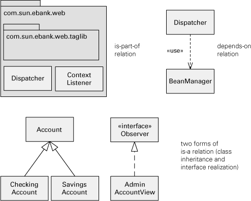
Software modeling notations, such as UML, provide a variety of constructs that can be used to represent modules. Figure 1.2 shows some examples for modules using UML notation. Figure 1.3 shows how the three basic relations native to module views are denoted using UML.
Figure 1.2 Examples of module notation in UML. A module may be represented as a class or a package. More specific types of modules can be indicated with stereotypes (as in Figure 1.4).

Figure 1.3 Examples of module relations in UML
![]()
Appendix A describes how UML can be used to show different module views, as well as C&C and allocation styles.
UML has a class construct, which is the object-oriented specialization of a module as described here. UML packages are used to represent an aggregation of modules. UML packages can represent, for example, layers, subsystems, and collections of implementation units that live together in the implementation namespace.
![]()
Stereotype is a UML extension mechanism that allows the definition of a new type of modeling element or relation based on an existing UML element or relation.
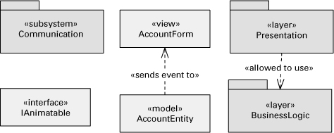
UML was originally created to model object-oriented systems. It is now considered a general-purpose modeling language. As a result, UML elements and relations are generic; that is, they are not specific to implementation technologies or platforms. But you can define stereotypes to specialize the UML symbols. A stereotype is a UML extension mechanism and is represented in diagrams as a label in guillemets («stereotype label»). Figure 1.4 shows some examples. If used correctly, stereotypes make your UML diagrams more expressive. The UML specification provides a number of standard stereotypes, but you can also create your own.
Figure 1.4 Examples of UML elements and relations with stereotypes
![]()
Try to become familiar with UML standard stereotypes, as well as other stereotypes commonly used in your organization.
1.4.3 Dependency Structure Matrix
A dependency structure matrix (DSM) is a table that shows modules as the column and row headings and dependencies as the table cells. The DSM is built as a square matrix (that is, a matrix with same number of rows and columns) where element ij is nonzero if there is a dependency between module i and module j in the architecture.
![]()
A dependency structure matrix is a table that shows modules as the row and column headers; a cell is nonzero if and only if there is a dependency between the row’s module and the column’s module.
Section 2.2.4 has examples and more information about DSMs.
Some tools that create DSMs can automatically interchange between class diagrams or box-and-line diagrams and DSMs. DSM-based tools are more commonly used for architecture management and enforcement for systems that are already implemented—the DSM is obtained by reverse-engineering the code.
1.4.4 Entity-Relationship Diagram
An entity-relationship diagram (ERD) is a notation specifically used for data modeling. It shows data entities that require a representation in the system and their relationships. These relationships can be one-to-one, one-to-many, or many-to-many.
![]()
Section 2.6.4 has examples and more information about ERDs.
1.5 Relation to Other Views
Module views are commonly mapped to component-and-connector views. The implementation units shown in module views have a mapping to components that execute at runtime. Sometimes, the mapping is quite straightforward, even one-to-one. More often, a single module will be replicated as part of many runtime components and a given component could map to several modules.
![]()
Components are discussed at length in Section 3.2.
Module views also provide the software elements that are mapped to the diverse nonsoftware elements of the system environment in the various allocation views.
![]()
Allocation views are described in Chapter 5.
A common problem is the overloading of module views with information pertaining to other views. This can be quite useful when done in a disciplined fashion but can also lead to confusion. For example, showing a remote procedure call connection in a module view is implicitly introducing the “connector” concept from a component-and-connector view. The module views are often confused with views that demonstrate runtime relations. A module view represents a static partitioning of the software implementation units; therefore, multiple instances of objects—data repositories and networks, for example—are not shown in this view.
1.6 Summary Checklist
• Modules pertain to the way in which a system’s software is decomposed into manageable units of responsibilities, which is one of the important forms of system structure.
• Modules are related to one another by forms of is-part-of, depends-on, and is-a relations.
• A module view provides a blueprint for the source code and the data model.
• Expect to have at least one module view in your documentation package.
• You should not depend on a module name to define the functional duties of the module: use the responsibility property.
• Document module interface(s) to establish a module’s role in the system.
• Module views are commonly mapped to component-and-connector views. In general, a module may participate in many runtime components.
1.7 Discussion Questions
1. What is it possible and not possible to say about data flow by looking at a module view? What about control flow? What can you say about which modules interact with which other modules?
2. Which properties of a module might you think of as worthy of having special notational conventions to express them, and why? For example, you might want to color a commercial-off-the-shelf module differently from modules developed in-house.
3. The depends-on relation among modules is very general. What specific types of dependencies might be reflected in a module view?
4. A primary property of a module is its set of responsibilities. How do a module’s responsibilities differ from the requirements that it must satisfy?
5. When documenting a particular system, you might wish to combine modules into an aggregate, to market them as a combined package, for example. Would this package itself be a module? That is, are all aggregates of modules themselves modules?
6. Would you show libraries or frameworks on which your system depends as modules in your module views?
1.8 For Further Reading
DeRemer and Kron (1976) describe programming-in-the-small languages for writing modules and a “module interconnection language” for knitting those modules together. Prieto-Diaz and Neighbors (1986) present a survey of module interconnection languages that are specifically designed to support module interconnection, and they include brief descriptions of some software development systems that support module interconnection.
The chapter on the Module Architecture View in the book by Hofmeister, Nord, and Soni (2000) describes a view of a system in terms of modules and layers and how to represent them in UML.