B. SysML—Systems Modeling Language

With John D. McGregor
Although not intended as a dedicated architecture description language, the Systems Modeling Language (SysML) provides sufficient constructs to meet many of the needs of a systems engineer. The engineer can represent the topology of the hardware and allocate software units to those hardware units. It is possible to represent the various architecture views needed to document a software architecture and particularly to show combined views of hardware and software.
SysML is a general-purpose systems-modeling language intended to support a broad range of analysis and design activities for systems-engineering applications. Systems engineers begin with a general problem statement, evolve toward a more specific problem statement, and eventually allocate portions of the problem to various solution elements. SysML is defined so that sufficient detail can be specified to support a variety of automated analysis and design tools.
SysML is a standard maintained by the Object Management Group (OMG) and was developed by OMG in cooperation with the International Council on Systems Engineering (INCOSE). SysML was developed as a profile of the Unified Modeling Language (UML). Being a profile means that SysML reuses much of UML, but it also provides the extensions necessary to meet the needs of systems engineers. The extensive overlap facilitates the interactions between systems engineers writing in SysML and software engineers writing in UML. SysML retains the extensibility of UML by including the UML elements necessary to define the SysML constructs.
The SysML standard defines several diagram types, shown in Table B.1. The first column lists those UML diagram types that SysML reuses unchanged. The second column lists those UML diagram types that have been modified. The third column lists those diagram types unique to SysML. As a convention, SysML diagrams have an enclosing frame with a diagram type designator. The two or three letters following each name in the table form the designator used in the enclosing frame of each diagram to identify the diagram type. A SysML model is composed of several diagram instances, usually from several different diagram types.

B.1 Architecture Documentation
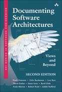
A SysML model is an aggregation of diagram instances, which together completely describes the target. SysML can be used to construct an ISO/IEC 42010-compliant description, or it may describe the architecture of the system in one model. A SysML model is typically organized using packages, each of which defines a namespace. A package contains a set of diagrams and may import diagrams from other packages. SysML supports the standard definitions of viewpoint and view and has stereotypes for each one. In SysML, a view is represented as a package that contains information conforming to a specific viewpoint. Figure B.1 shows an example of a viewpoint and three conforming views described in a SysML block diagram.
Figure B.1 SysML block diagram
B.2 Requirements
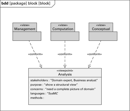
SysML provides a means of establishing traceability among requirements and from requirements to their implementation as described in the architecture. Figure B.2 illustrates these relations. Requirements are related to each other for a variety of reasons, including one requirement being derived from another. A requirement can be related to the elements that satisfy the requirement through the satisfy relationship. This technique links the requirements to the architecture; for example, Payment is represented in both Figure B.2 and Figure B.3.
Figure B.2 SysML requirement diagram
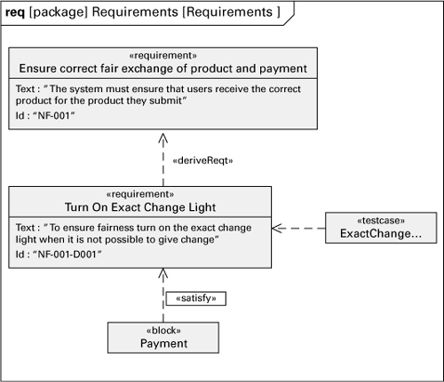
Figure B.3 Generalization view in SysML

B.3 Documenting a Module View
Table B.2 provides a mapping of the requirements of a Views and Beyond module view to the SysML block diagram. The block is a SysML model element that is similar to a class in UML. The block diagram illustrates the relations among a set of blocks, including the usual is a, depends on, and is part of. This is basic structural information that will be referenced by other views. Figure B.3 shows an is-a module view using the SysML block diagram.
Table B.2 Mapping the concepts of a module view to SysML
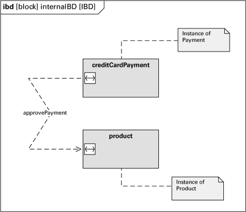
B.4 Documenting a Component-and-Connector View
The block and internal block diagrams can be used together to provide a C&C view. The block diagram is used to define the component types and their relations. The internal block diagram is used to represent the component instances and their connections. Table B.3 shows the mapping of the requirements of a C&C view to SysML. Figure B.4 shows a C&C view of the blocks in Figure B.3.
Table B.3 Mapping the concepts of a C&C view to SysML

Figure B.4 Internal block diagram
B.5 Documenting an Allocation View
Systems engineers use allocation relations to associate many different types of information. SysML has several ways to show various types of allocation. The most common allocation view allocates the software to hardware. Table B.4 gives a mapping of the allocation view requirements onto a SysML internal block diagram.
Table B.4 Mapping of allocation view concepts to SysML
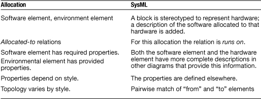
Figure B.5 shows the “allocatedFrom” partition in a block definition. It is also possible to have an “allocatedTo” partition, giving two-way traceability. Allocations can also be specified on a large number of other model elements. SysML adds a table style for allocation; see Table B.5 for an example.
Figure B.5 Allocation of software to hardware in SysML

Table B.5 Table view of allocation

B.6 Documenting Behavior
SysML has two ways to model behavior: the sequence and activity diagrams. The sequence diagram usually portrays a single path or scenario. It is unchanged from the UML definition. The activity diagram, in both SysML and UML, can represent a complete algorithm, but the SysML activity diagram has added a number of extensions that support describing a broader range of behaviors more accurately. These additions include the ability to represent inputs and outputs at various points along the paths of the diagram, and the ability to model an activity as a first-class entity that can appear in a class diagram and can participate in specification/generalization relations. Figure B.6 shows a small activity diagram.
Figure B.6 A SysML activity diagram

B.7 Documenting Interfaces
SysML provides an interface model element in the block diagram type. The interface can also have associated constraints. As with all of the SysML diagram types, constraints may be added to any of the elements in a diagram, usually to specify the semantics of the element to which the constraint is attached. In Figure B.7, a constraint is used to capture the semantics of one dependency of the View interface.
Figure B.7 Interface documentation in SysML

B.8 Summary
A number of commercial and open-source tools support SysML. The Topcased project (topcased.org) provides editors for both the graphical and XML-based syntaxes of SysML. Commercial tools such as Rhapsody, MagicDraw, and Enterprise Architect support SysML.
At this writing, SysML version 1.2 is the latest release. As the use of SysML expands, expect that many change requests will be submitted and the language will evolve to more fully meet the needs of the systems-engineering community. Changes to UML may also be reflected in SysML, because they share a large portion of their metamodels.