
2. A Tour of Some Module Styles
In this chapter, we look at six important module styles:
• The decomposition style, used to show the structure of modules and submodules (that is, containment relations among modules)
• The uses style, used to indicate functional dependency relations among modules
• The generalization style, used to indicate specialization relations among modules
• The layered style, used to describe the allowed-to-use relation in a restricted fashion between groups of modules called layers
• The aspects style, used to describe particular modules called aspects that are responsible for crosscutting concerns
• The data model style, used to show the relations among data entities
2.1 Decomposition Style
2.1.1 Overview
By taking the elements and the properties of module views and focusing on the is-part-of relation, we get the decomposition style. A decomposition view describes the organization of the code as modules and submodules and shows how system responsibilities are partitioned across them. Almost all architects begin with the decomposition style. Architects tend to attack a problem with divide-and-conquer techniques, and a decomposition view records their campaign.
The criteria used for decomposing a module into smaller modules include:
• Achievement of certain quality attributes. For example, to support modifiability, the information-hiding design principle calls for encapsulating changeable aspects of a system in separate modules, so that the impact of any one change is localized.
• Build-versus-buy decisions. Some modules may be bought in the commercial marketplace, reused intact from a previous project, or obtained as open-source software. These modules already have a set of responsibilities implemented. The remaining responsibilities then must be decomposed around those established modules.
• Product line implementation. To support the efficient implementation of products of a product family, it is essential to distinguish between common modules, used in every or most products, and variable modules, which differ across products.
• Team allocation. To allow implementation of different responsibilities in parallel, separate modules that can be allocated to different teams should be defined. The skills of developers also influence the decomposition. For example, if specialized Web developers are available, modules that handle the Web UI should be kept separate.
A useful design heuristic holds that a module is small enough if it could be discarded and begun again if the programmer(s) assigned to implement it left the project.
A decomposition view may represent the first pass at a detailed architecture design; the architect may subsequently introduce other types of relations and module specializations. The decomposition view defines the modules that may appear in uses, layered, generalization, and other module-based views.
2.1.2 Elements, Relations, and Properties
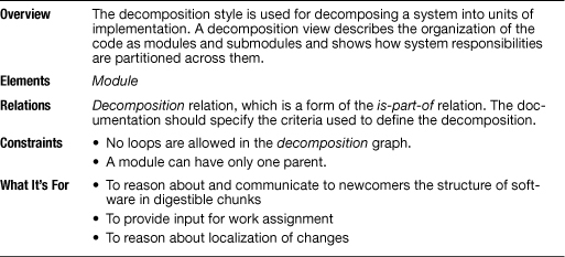
Table 2.1 summarizes the characteristics of the decomposition style. Elements of the decomposition style are modules, as described in Section 1.2. Some modules that aggregate other modules can be called subsystems. The principal relation, the decomposition relation, is a form of the is-part-of relation and has as its primary constraint the guarantee that an element can be a part of at most one aggregate.
Table 2.1 Summary of the decomposition style
![]()
See “Coming to Terms: Subsystem” on page 73, in this chapter.
![]()
The element catalog of an architecture view provides various information about the elements in that view. Element catalogs are described in Section 10.1.
The module decomposition may define whether the submodules are visible within only the aggregate module—the parent—or also to other modules. The visibility of submodules can be described in the view’s element catalog or conveyed graphically, for example by showing interface lollipops inside or outside the aggregate module, as in Figure 1.1.
2.1.3 What the Decomposition Style Is For
A decomposition view presents the responsibilities of a system in intellectually manageable pieces that are refined to convey more and more details. Therefore, this style is well suited to support the learning process about a system. Besides the obvious benefit for the architect to support the design work, this style is an excellent learning and navigation tool for newcomers to the project and other people who do not necessarily have the whole functional structure of the system memorized. The grouping of responsibilities shown in this style also builds a useful basis for defining configuration items within a configuration management framework.
![]()
Refinement is covered in Section 6.1.
A decomposition view most often serves as the input for the work assignment view of a system, which maps parts of a software system onto the organizational units, or teams, that will be implementing and testing them. A decomposition view also provides some support for analyzing effects of changes, but because this view does not show all the dependencies among modules, you cannot expect to do a complete impact analysis. Here, views that elaborate the dependency relations more thoroughly, such as the uses style described later, are required.
![]()
The work assignment style is presented in Section 5.4.
2.1.4 Notations for the Decomposition Style
Informal Notations
In informal notations, modules in the decomposition style are usually depicted as named boxes that contain other named boxes. Decomposition may also be shown by listing the module names and using indentation to indicate is part of, as in Figure 2.4 (in Section 2.1.6).
The nesting notation can use a thick border suggesting opaqueness—and explained in the key—indicating that children are not visible outside the parent. If a visual notation is not available for indicating visibility, it can be defined textually, as is done for other properties.
UML
In UML, the package construct can be used to represent modules that contain other modules. A package can contain classes and other packages; the class box is normally used for the leaves of the decomposition.
In UML, decomposition is depicted in one of two ways:
1. Modules may be nested, as in Figure 2.1.
Figure 2.1 In UML, module decomposition is shown by nesting, with the aggregate module shown as a package.

2. A succession of two diagrams can be shown, with the second a depiction of the contents of a module shown in the first. Figures 2.2 and 2.3 (in Section 2.1.6) illustrate this approach.
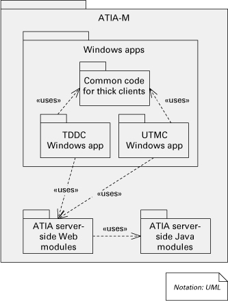
Figure 2.2 Top-level decomposition view for the ATIA system

Figure 2.3 Refinement of ATIA-M server-side Java modules showing how it is further decomposed into submodules

Other properties, such as the modules’ responsibilities, are given textually, perhaps using an annotation. Stereotypes can provide additional information for the type of the module.
2.1.5 Relation to Other Styles
It is possible, and often desirable, to map between a decomposition view and one or more component-and-connector views. For now, it is sufficient to say that the point of providing such a mapping is to indicate how the software implementation structures map onto runtime structures: generally, a many-to-many relationship. The same module might implement all or parts of several components or connectors. Conversely, one component might require several modules for its implementation.
![]()
Section 3.5 also discusses the mapping between modules and components. Documenting the mapping is described in Section 10.2.
The decomposition style is closely related to the work assignment style, a kind of allocation style. The work assignment style maps modules resulting from a decomposition to a set of teams responsible for implementing and testing those modules.
![]()
The work assignment style is described in Section 5.4.
2.1.6 Examples Using the Decomposition Style
Adventure Builder
The example software architecture document that accompanies this book online contains an example of a decomposition view for the Adventure Builder (2010) system. See wiki.sei.cmu.edu/sad.
The ATIA-M System
Army Training Information Architecture-Migrated (ATIA-M) is a large Web-based, Java EE application that supports training in the U.S. Army. It has “thick clients”: Windows desktop applications developed using .NET (C#) that communicate with the server-side Java EE components using Web services technology.
Figure 2.2 shows the top-level module decomposition for the entire ATIA-M system, itself a module. The code is divided into three large modules:
• Windowsapps contains the code of the thick clients. The three submodules correspond to Training and Doctrine Development Tool (TDDT), Unit Training Management Configuration (UTMC), and a separate submodule with common code used by the different Windows applications. TDDT and UTMC were the two Windows applications originally planned, but others could be added.
![]()
Figure 2.2 is the first of many examples of architecture documentation fragments from real systems. When examining these examples, keep in mind the considerations stated in Section I.5, in the introduction to Part I. The descriptions of the elements we provide cannot be derived from the figures; rather, they rely on additional documentation that would accompany the diagrams in an architecture document.
• ATIA server-side Web modules contains all non-Java modules that would be deployed to server machines. The Web modules include JavaServer Pages (JSP) files, JavaScript and HTML code, and applets.
• ATIA server-side Java modules contains all Java source code in ATIA that would run on application servers. This module does not include JSP, JavaScript, HTML, applet, or thick-client code.
The decomposition of Windowsapps into three submodules is shown in Figure 2.2. The decomposition of ATIA server-side Java modules, on the other hand, was captured in another module view diagram, shown in Figure 2.3.
A-7E Avionics System
An example of the decomposition style comes from the A-7E avionics software system described in Chapter 3 of the book by Bass, Clements, and Kazman (2003). Figure 2.4 shows the primary presentation part of the view. The figure names the elements and shows the is-part-of relation among them for the A-7E system. The decomposition relation is conveyed by indentation.
Figure 2.4 The decomposition of the A-7E software architecture results in three top-level modules (Hardware Hiding, Behavior Hiding, and Software Decision Hiding) and is-part-of relations (Bass, Clements, and Kazman 2003, p. 59). In this presentation, is part of is indicated by textual indentation.

![]()
The primary presentation is the (typically) graphical portion of an architecture view, as described in Chapter 10.
In this example, the criterion for decomposition is the information-hiding principle, which holds that there should be a module to encapsulate responsibilities likely to change together. A module’s responsibilities, then, are described in terms of the information-hiding secrets it encapsulates.
This diagram shows that in A-7E, the first-order decomposition produced three modules: Hardware Hiding, Behavior Hiding, and Software Decision Hiding. Each of these modules is decomposed into two to six submodules, which are in turn decomposed, and so forth, until the granularity is fine enough to be manageable.
The A-7E decomposition view documentation describes the responsibilities of the three highest-level modules in the element catalog as follows:
• Hardware Hiding Module: The Hardware Hiding Module includes the procedures that need to be changed if any part of the hardware is replaced by a new unit with a different hardware/software interface but with the same general capabilities. This module implements “virtual hardware” or an abstract device that is used by the rest of the software. The primary secrets of this module are the hardware/software interfaces. The secondary secrets of this module are the data structures and algorithms used to implement the virtual hardware.
• Behavior Hiding Module: The Behavior Hiding Module includes procedures that need to be changed if there are changes in requirements affecting the required behavior. Those requirements are the primary secret of this module. These procedures determine the values to be sent to the virtual output devices provided by the Hardware Hiding Module.
• Software Decision Hiding Module: The Software Decision Hiding Module hides software design decisions that are based upon mathematical theorems, physical facts, and programming considerations such as algorithmic efficiency and accuracy. The secrets of this module are not described in the requirements document. This module differs from the other modules in that both the secrets and the interfaces are determined by software designers. Changes in these modules are more likely to be motivated by a desire to improve performance or accuracy than by externally imposed changes.
![]()
If you use a module decomposition structure to organize your project, you will find it useful to focus on a specific level of the hierarchy as your organizing motif, chosen based on a manageable granularity.
The A-7E decomposition view documentation then goes on to describe the second-level modules.
In the case of the A-7E architecture, the second-level module structure was enshrined in many ways: Design documentation, configuration-controlled files, test plans, programming teams, review procedures, and project schedule and milestones all were pegged to this second-level module structure as their unit of reference.
Coming to Terms: Subsystem
When documenting a module view of a system, you may choose to identify certain aggregated modules as subsystems. A subsystem can be pretty much anything you want it to be, but it often describes a part of a system that (1) carries out a functionally cohesive subset of the overall system’s mission, (2) can be executed independently, and (3) can be developed and deployed incrementally. The software system of a Mars exploratory robot, for example, may be divided into subsystems responsible for:
• Communication
• Motion
• Power management
• Navigation
• Monitoring its own health and status
Not just any portion of a system is a subsystem. In our exploratory robot example, a math utility library is certainly a portion of a system and an aggregation of modules and even has coherent functionality. But the library is unlikely to be called a subsystem, because it lacks the ability to operate independently to do work that’s recognizably part of the overall system’s purpose.
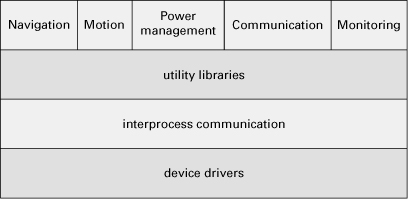
Subsystems do not partition a system into completely separate parts, because some parts are used in more than one subsystem. For example, suppose that the exploratory robot system has the layered design shown in Figure 2.5. In this case, a subsystem consists of one segment from the top layer, as well as any segments of any lower layers that it needs in order to carry out its responsibilities. A subset of the system formed in this way is often called a slice, or a vertical slice.
Figure 2.5 Layered design of a hypothetical exploratory robot system
The “more or less independent” nature of a subsystem makes it ideal for dividing up a project’s work. You may, for example, ask an analyst to examine the performance of a subsystem. A subsystem can often be fielded and accomplish useful work before the whole system is complete. A subsystem makes a convenient package to hand off to a team or a subcontractor to implement. The fact that it executes more or less independently allows that team to work more or less independently even through testing.
In the UML world, <<subsystem>> is a stereotype of component. It represents a large-scale component that embodies other components. According to the UML 2.2 specification, a subsystem is:
A unit of hierarchical decomposition for large systems. A subsystem is commonly instantiated indirectly. Definitions of subsystems vary widely among domains and methods, and it is expected that domain and method profiles will specialize this construct.
In previous versions of UML, <<subsystem>> was a stereotype of package and still today it is common to find packages with that stereotype in UML diagrams. Regardless of the notation used, a subsystem can represent a group of modules (implementation units) or a group of components with runtime presence.
You may decide to identify subsystems in your design. If you do, make sure that your rationale explains why you chose the ones you did.
2.2 Uses Style
2.2.1 Overview
![]()
Uses is a form of dependency that can exist between two modules. A uses B if the correctness of A depends on the presence of a correct implementation of B.
The uses style results when the depends-on relation is specialized to uses. A module uses another module if its correctness depends on the correctness of the other. Whereas the module decomposition style shows only the organization of the implementation units as modules and submodules, a uses style goes one step further to reveal which modules use which other modules. This style tells developers what other modules must exist for their portion of the system to work correctly. This style enables incremental development and the deployment of useful subsets of full systems.
2.2.2 Elements, Relations, and Properties
Table 2.2 summarizes the characteristics of the uses style. The elements of this style are the modules as described in Section 1.2. We define a specialization of the depends-on relation to be the uses relation, whereby one module requires the correct implementation of another module for its own correct functioning. This view makes explicit which modules use which other modules to achieve their responsibilities.
Table 2.2 Summary of the uses style

2.2.3 What the Uses Style Is For
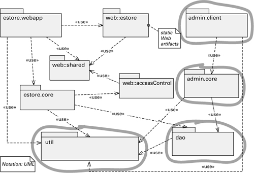
This style is useful for planning incremental development, system extensions and subsets, debugging and testing, and gauging the effects of specific changes. Figure 2.6 shows the primary presentation of a uses view and how it can help with incremental development. To define incremental subsets, modules should be defined at the right level of granularity. In the example, admin.core may not need the entire dao package, only a submodule of it; the diagram should then show the submodules of dao.
Figure 2.6 In this uses view, suppose the incremental development plan called for module admin.client in the next release. Based on the uses relation, the diagram highlights what other modules need to be present: admin.core, dao, and util.
The uses view also helps in managing the dependencies of a system that is being built or maintained. The goal of this task is to keep complexity under control and avoid degradation in the modifiability of the system due to the addition of undesirable dependencies.
![]()
See “Coming to Terms: Uses” on page 81, in this chapter, for more about loops in the uses relation.
2.2.4 Notations for the Uses Style
Informal Notations
The uses relation can be documented as a two-column table, with using elements on the left and the elements they use listed on the right. Alternatively, informal graphical notations can show the relation by using the standard box-and-line diagram with a key. For defining subsets, a tabular—that is, nongraphical—notation is sometimes a better alternative. It is easier to look up the detailed relations in a table than to find them in a diagram, which can rapidly grow too cluttered to be helpful unless the diagram is partitioned using decomposition refinement.
![]()
Decomposition refinement is discussed in Section 6.1.
Semiformal Notations
UML
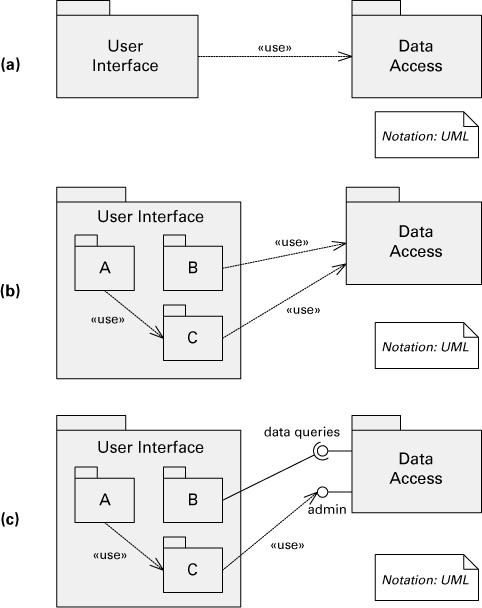
The uses style is easily represented in UML. UML packages can be used to represent modules; the uses relation is depicted as a dependency with the stereotype <<use>>. In Figure 2.7(a), the User Interface module has a uses dependency on the Data Access module.
Figure 2.7 (a) The User Interface module is an aggregate module with a uses dependency on the Data Access module. We use UML package notation to represent modules and the specialized form of depends-on arrow to indicate a uses relation.
(b) Here is a variation of Figure 2.7(a) in which the User Interface module has been decomposed into modules A, B, and C. At least one of the modules must depend on the Data Access module or the decomposition would not be consistent.
(c) In UML we can represent the uses relations and also show interfaces explicitly. This version shows that the Data Access module has two interfaces, which are used by modules B and C, respectively. Both the socket lollipop connection and the <<use>> dependency connected to the lollipop indicate uses relations.
Dependency Structure Matrix
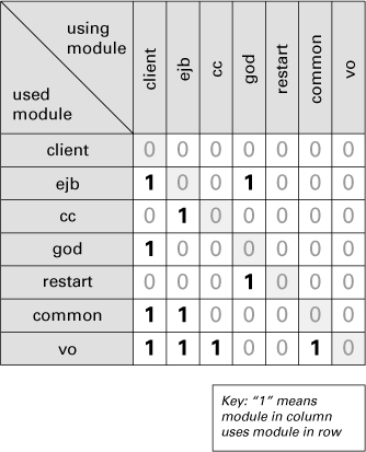
The uses relation can be documented as a square matrix, with the modules listed as rows and columns. A mark in the ith column and jth row indicates that module i uses module j. This simple representation has evolved and been used in automated tools to create dependency structure matrices (DSMs).
![]()
DSMs need a key too! In the key, say whether a value in row i and column j means that module i depends on module j or module j depends on module i. Both alternatives are possible.
A diagram like the UML package diagram in Figure 2.8 can be seen as a directed graph; the packages are the vertices and the dependencies are the edges. A DSM is the matrix representation of a directed graph. The cell corresponding to column i and row j is nonzero if there is an edge from vertex i to vertex j in the graph (that is, module i uses module j). Figure 2.9 shows the DSM for the UML diagram in Figure 2.8.
Figure 2.8 UML package diagram showing <<uses>> dependencies
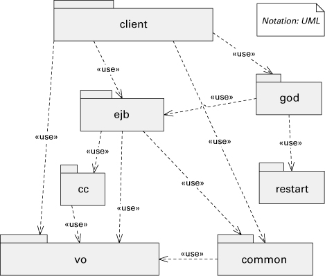
Figure 2.9 DSM for the UML diagram in Figure 2.8
2.2.5 Relation to Other Styles
The uses style also goes hand in hand with the layered style, with its allowed-to-use relation. An allowed-to-use relation usually comes first and contains coarse-grained directives defining the degrees of freedom for implementers. Once implementation choices have been made, the uses view emerges and governs the production of incremental subsets.
When a module contains submodules, the decomposition requires that any uses relation involving the aggregate module be mapped to a submodule using that relation. In Figure 2.7(b), the User Interface module is decomposed into modules A, B, and C. At least one of the modules must depend on the Data Access module; otherwise, the decomposition is not consistent.
A uses view can also show interfaces explicitly. In Figure 2.7(c), the Data Access module has two interfaces, which are used by modules B and C, respectively.
![]()
Chapter 7 has more information about interfaces.
2.2.6 Examples Showing the Uses Style
Adventure Builder
The example software architecture document accompanying this book online contains an example of a uses view for the Adventure Builder (2010) system. See wiki.sei.cmu.edu/sad.
The ATIA-M System
Figure 2.10 shows the diagram from a top-level uses view for the ATIA-M system (it also shows decomposition). In the architecture documentation, it could have superseded the decomposition view (see Figure 2.2) for the same system.
Figure 2.10 Top-level uses view for the ATIA-M system
ECS
EOSDIS Core System (ECS) is a NASA system. A constellation of satellites collect measurements about Earth and send the data to ground stations. ECS controls spacecraft and instruments, processes data, and produces refined data that are stored in several distributed data centers and made available to scientists around the world. Figure 2.11 is a small excerpt of a uses view’s primary presentation from the ECS system. The notation is textual, using the tabular format mentioned earlier. Like most primary presentations, this one names only the elements; they are defined in the view’s supporting documentation (not shown here).
Figure 2.11 Excerpt of the ECS system uses view, documented as a table. The left column mirrors the system’s module decomposition structure.

2.3 Generalization Style
2.3.1 Overview
![]()
Even though this style shares the terms parent and child with the decomposition style, they are used differently. In decomposition, a parent consists of its children. In generalization, parents and children have things in common.
The generalization style results when the is-a relation is employed. This style is useful when an architect wants to support extension and evolution of architectures and individual elements. Modules in this style are defined in such a way that they capture commonalities and variations. When modules have a generalization relationship, the parent module is a more general version of the child modules. (The parent module owns the commonalities, and the variations are manifested in the children.) Extensions can be made by adding, removing, or changing children; a change to the parent will automatically change all the children that inherit from it, which could support evolution if the change is appropriate for all the children.
Generalization may represent inheritance of either interface, implementation, or both. Within an architecture description, the emphasis is on sharing and reusing interfaces and not so much on implementations.
2.3.2 Elements, Relations, and Properties
Table 2.3 summarizes the characteristics of the generalization style. The element of the generalization style is the module; the relation is generalization, which is the is-a relation defined in Section 1.2. In this relation, one module is a generalization (parent) of other modules (children), and these other modules are specializations of the first.
Table 2.3 Summary of the generalization style
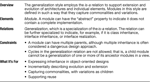
A module can be abstract. Such a module does not contain a complete implementation. Modules that are children of an abstract module need to provide the necessary implementations or else they should be abstract as well.
A module that inherits information is referred to as a descendant; the module providing the information is an ancestor. Cycles are not allowed. That is, a module cannot be an ancestor or a descendant of itself.
The fact that module A inherits from module B using interface realization is a promise that module A complies to interface B. This strategy is useful when variants of a module with different implementations are needed and one implementation of the module can substitute for another implementation with little or no effect on other modules. In object-oriented designs, class inheritance indicates that a module inherits behavior from its ancestors and may modify it to achieve its specialized behavior. Interface inheritance is also possible when we want a child interface that adds operations to the list of operations defined by the parent interface.
2.3.3 What the Generalization Style Is For
The generalization style can be used to support
• Object-oriented designs. The generalization style is the predominant means for expressing an inheritance-based, object-oriented design for a system.
• Extension. It is often easier to understand how one module differs from another, well-known module rather than to try to understand a new module from scratch. Thus, generalization is a mechanism for producing incremental descriptions to form a full description of a module.
• Local change or variation. One purpose of architecture is to provide a stable global structure that accommodates local change or variation. Generalization is one approach to define commonalities on a higher level and to define variations as children of a module.
• Reuse. Finding reusable modules is a by-product of the other purposes. Suitable abstractions can be reused at the interface level alone, or the implementation can be included as well. The definition of abstract modules creates an opportunity for reuse.
2.3.4 Notations for the Generalization Style
UML
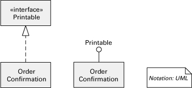
Expressing generalization lies at the heart of UML. Modules are typically shown as classes or interfaces. Figure 2.12 shows the basic notation available in UML for class or interface inheritance. Figure 2.13 shows how UML expresses interface realization.
Figure 2.12 In UML, class or interface inheritance is represented by a solid line with a closed, hollow arrowhead. UML allows an ellipsis (. . .) in place of a submodule, indicating that a module can have more children than shown and that additional ones are likely. Module Shape is the parent of modules Polygon, Circle, and Spline, each of which is in turn a subclass, child, or descendant of Shape. Shape is more general; its children are specialized versions. The arrow points toward the more general entity.
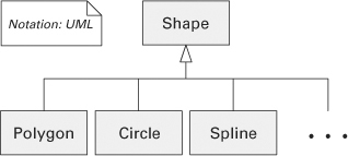
Figure 2.13 Interface realization (sometimes called interface implementation) is also a kind of generalization. It can be expressed in UML in two ways: (1) a dashed line with a closed hollow arrowhead going from the module to the interface it realizes; (2) a lollipop symbol for the interface connected to the module that implements it. Thus the two notations in the figure are equivalent. However, the one on the left is more convenient when multiple modules realize the same interface.
![]()
Chapter 7 discusses how to document interfaces.
2.3.5 Relation to Other Styles
Inheritance and interface realization relationships complement other module relations and are often found in module views along with uses relations and package decompositions. But for designs that involve a complex hierarchy of modules, it is useful to show inheritance relationships in a diagram separate from other types of relationships.
2.3.6 Examples Using the Generalization Style
ArchE
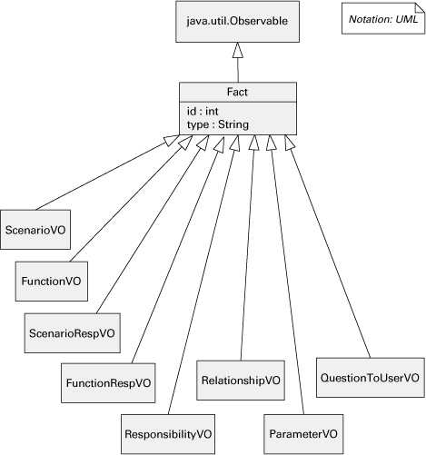
Figure 2.14 shows part of a generalization view from the SEI Architecture Expert (ArchE) tool. This tool allows an architect to create the architecture design for a system based on quality attribute requirements, feature requirements, and preexisting pieces of design. Internally, ArchE uses a rule engine that manipulates data elements called facts. Various operations are performed on any Fact object; other operations are specific to the subclasses of Fact.
Figure 2.14 The primary presentation for ArchE’s generalization view. This system uses internally a rule engine, and many operations are defined on a class called Fact. In addition, specific functionality exists to deal with different kinds of facts and hence the generalization in this figure. The classes shown here also appear in other diagrams, which show the attributes and operations available in each class, as well as uses relations among these and other modules that are part of the system.
PetStore
Figure 2.15 shows part of the generalization view of the PetStore application. This is a multi-tier, Web-based application that implements an online pet store. The generalization view shows several important hierarchies in the system (Figure 2.15 shows a subset of them).
Figure 2.15 Part of the primary presentation of the generalization view for the PetStore application. It shows a hierarchy of classes that represent events in the system, and an interface realization. The package on the right is part of a Web application framework (waf), which offers an event-handling service. An application such as PetStore has to define the application-specific events. The events are used for the interaction of other modules in the system (not shown) following the model-view-controller pattern.

2.4 Layered Style
2.4.1 Overview
The layered style, like all module styles, reflects a division of the software into units. In this case, the units are layers. Each layer represents a grouping of modules that offers a cohesive set of services. There are constraints on the allowed-to-use relationship among the layers: the relations must be unidirectional. The layered view of architecture, shown with a layer diagram, is one of the most commonly used views in software architecture. However, it often is poorly defined, and so often misunderstood. Because true layered systems promote modifiability and portability, architects have an incentive to show their systems as layered, even if they are not.
![]()
A layer is a grouping of modules that together offer a cohesive set of services to other layers. The layers are related to each other by the strictly ordered relation allowed to use.
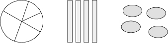
Layers completely partition a set of software, and each partition—through a public interface—provides a cohesive set of services. But that’s not all. Figure 2.16, which is intentionally vague about what the units are and how they interact, shows three divisions of software—you’ll have to take our word that each division provides a cohesive set of services—but none of them constitutes a layering. What’s missing?
Figure 2.16 Three different divisions of software. Is any of them layered?
Layering has one more fundamental property: The layers are created to interact according to a strict ordering relation. Herein lies the conceptual heart of layers. If (A, B) is in this relation, we say that the implementation of layer A is allowed to use any of the public facilities provided by layer B.
![]()
Element A uses element B if A’s correctness depends on a correct implementation of B being present.
By uses, we mean the very specific term defined in Section 2.2 for the uses style, but the definition has some loopholes. If A is implemented using the facilities in B, is it implemented using only B? Maybe or maybe not. For example, assume that layers are depicted horizontally, one on top of the other. Some layering schemes allow a layer to use the public facilities of any lower layer, not just the nearest lower layer. Other layering schemes have so-called layers that are collections of utilities and can be used by any layer. But no architecture that can be validly called layered allows a layer to use, without restriction, the facilities of a higher layer. Allowing unrestricted upward usage destroys the desirable properties that layering brings to an architecture; this will be discussed shortly. Usage in layers generally flows downward. A small number of well-defined special cases may be permitted, but these should be few and regarded as exceptions to the rule. Hence, the architecture in Figure 2.17 resembles a layering but is not.
Figure 2.17 There may be three layers here, but this is not a design in the layered style, which forbids upward uses.

Figure 2.17 shows why layers have been a source of ambiguity for so long: architects have been calling such diagrams layered when they are not. There is more to layers than the ability to draw separate parts on top of each other.
![]()
Remember that a system with a uses relation from a lower layer to a higher layer is not a layered system, strictly speaking.
In some cases, modules in a very high layer might be required to directly use modules in a very low layer where normally only next-lower-layer uses are allowed. The layer diagram or an accompanying document will have to show these exceptions. The case of software in a higher layer using modules in a lower layer that is not just the next lower layer is called layer bridging. If many of these are present, the system is poorly structured, at least with respect to the portability and modifiability goals that layering helps to achieve. Systems with upward usages are not, strictly according to the definition, layered. However, in such cases, the layered style may represent a close approximation to reality and also conveys the ideal design that the architect was trying to achieve.
Layers cannot be derived by examining source code. Layers are logical groupings that are wonderful aids in creating and communicating the architecture, but often they are not explicitly delimited in the source code. The source code may disclose what uses what, but the relation in layers is allowed to use.
Some of the criteria used in defining the layers of a system are an expectation that they will evolve independently on different time scales, that different people with different sets of skills will work on different layers, and that different levels of reuse are expected of the different layers.
2.4.2 Elements, Relations, and Properties
Table 2.4 summarizes the characteristics of the layered style.
Table 2.4 Summary of the layered style
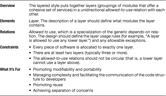
The elements of a layered view are layers. A layer is a cohesive collection of modules, each of which may be invoked or accessed. The modules in a layer can be anything: from modules that implement Web services to assembly-language subroutines to shared data. A requirement is that the modules have an interface by which their services can be triggered or accessed.
The relation among layers is allowed to use. For two layers having this relation, any module in the first is allowed to use any module in the second. Module A is said to use module B if A’s correctness depends on B being correct and present.
![]()
Element catalogs are described in Section 10.1.
Layers have the following properties, which should be documented in the element catalog accompanying the layer diagram.
• Contents. The description of a layer should provide guidelines to what modules should be in a layer and how to implement them. It can also explicitly list the software modules contained by each layer. Each module should be assigned to exactly one layer. Layers typically have labels that are descriptive but vague, such as “network communications layer” or “business rules layer”; a description is needed that identifies the complete contents of every layer.
• The software a layer is allowed to use. Is a layer allowed to use only the layer below, any lower layer, or some other? If a layer is segmented horizontally, are modules in a segment permitted to use modules in another segment of the same layer? This part of the documentation must also explain exceptions, if any, to the usage rules implied by the geometry.
![]()
Section 2.4.4 has more information about segmented layers.
See also “Perspectives: Calling Higher Layers” on page 100, in this chapter.
You should document the rationale for the choice of layer partitioning. Explain how each layer provides a cohesive set of responsibilities. This description helps to assign future modules to one layer or the other.
Suppose that module P1 is allowed to use module P2. Should P2 be in a lower layer than P1, or should they be in the same layer? Layers are not a function of just who uses what, but are the result of a conscious design decision that allocates modules to layers, based on such considerations as cohesion and the nature of likely changes. In general, P1 and P2 should be in the same layer if they are likely to be ported to a new application together or if together they provide different aspects of the same virtual machine to a usage community.
![]()
A virtual machine is a collection of modules that form an isolated, cohesive set of services that can execute programs. It’s sometimes called an abstract machine.
See “Coming to Terms: Virtual Machines” on page 99, in this chapter.
The preceding is an operational definition of cohesion. The cohesion explanation can also serve as a portability guide, describing the changes that can be made to each layer without affecting other layers.
2.4.3 What the Layered Style Is For
Layers help to bring quality attributes of modifiability and portability to a software system. A layer is an application of the principle of information hiding. The theory is that a change to a lower layer can be hidden behind its interface and will not impact the layers above it. As with all such theories, both truth and caveats are associated with it. The truth is that this technique has been used with great success to support portability. Machine, operating system, or other platform dependencies are hidden within a layer; as long as the interface for the layer does not change, technology-specific or product-specific parts can be exchanged, and the upper levels that depend only on the interface will work successfully.
![]()
See “Coming to Terms: Signature, Interface, API” on page 280, in Chapter 7.
The caveat is that interface means more than just the application programming interface (API) containing program signatures. An interface embodies all the assumptions that an external entity—in this case, a layer—may make. Changes in a lower layer that affect, say, a performance assumption will leak through its interface and may affect a higher layer.
A common misconception is that layers introduce additional runtime overhead. Although this may be true for naive implementations, sophisticated compile/link/load facilities can reduce additional overhead.
We have already mentioned that in some contexts, a layer may contain unused services. These unused services may needlessly consume a runtime resource, such as memory to store the unused code or a thread that is never launched. If these resources are in short supply, a sophisticated compile/link/load facility that eliminates unused code will be helpful.
Layers are part of the blueprint role that architecture plays for constructing the system. Knowing the layers in which their software resides, developers know what services they can rely on in the coding environment. Layers might define work assignments for development teams, although not always.
Layers are part of the communication role played by architecture. In a large system, the number of modules and the dependencies among them rapidly expand. Organizing the modules into layers with interfaces is an important tool for managing complexity and communicating the structure to developers.
Grouping into layers those modules that have the same technology abstraction or are cohesive with respect to their responsibilities helps to assign the implementation work across more specialized teams. For example, the modules in a presentation layer can be assigned to skilled GUI developers.
Layers help with the analysis role played by architecture. They support the analysis of the impact of changes to the design by enabling some determination of the scope of changes.
Layers that provide a virtual machine promote portability. For this reason, it is important to scrutinize the interface of such layers to ensure that portability concerns are addressed. The interface should not expose functions that are dependent on a particular platform; these functions should be hidden behind a more abstract interface that is independent of platform.
![]()
See “Coming to Terms: Virtual Machines” on page 99, in this chapter.
Because the ordering relationship among layers has to do with “implementation allowed to use,” the lower the layer, the fewer the facilities available to it. That is, the “worldview” of lower layers tends to be smaller and more focused on the computing platforms. Lower layers tend to be built using knowledge of the operating systems, communications channels, databases, and the like. These platform-specific layers are largely independent of the particular application that runs on them; they make the application more easily portable to a different platform.
2.4.4 Notations for the Layered Style
Informal Notations
Stack
Layers are almost always drawn as a stack of boxes. The allowed-to-use relation is denoted by geometric adjacency and is read from the top down, as in Figure 2.18 (note that the key could have said, “A layer is allowed to use any lower layer”).
Figure 2.18 Stack of boxes notation for layered designs

Layering is thus one of the few architecture styles in which connection among components is shown by geometric adjacency and not an explicit symbology, such as an arrow, although arrows can be used, as in Figure 2.19.
Figure 2.19 Layered design with allowed-to-use relations shown with arrows

Segmented Layers
Sometimes layers are divided into segments denoting a finer-grained aggregation of the modules. Often, this occurs when a preexisting set of units, such as imported modules, share the same allowed-to-use relation. When this happens, the creator of the diagram must specify what usage rules are in effect among the segments. Many usage rules are possible, but they must be made explicit. In Figure 2.20, the top and the bottom layers are segmented. Segments of the top layer are not allowed to use each other, but segments of the bottom layer are. If you draw the same diagram without the arrows, it will be harder to differentiate the usage rules within segmented layers. Layered diagrams are often a source of ambiguity because the diagram does not make explicit the allowed-to-use relations.
Figure 2.20 Layered design with segmented layers

Rings
A notational variation is to show layers as a set of concentric circles, or rings. The innermost ring corresponds to the lowest layer; the outermost ring, the highest layer. A ring may be subdivided into sectors, meaning the same thing as the corresponding layer being segmented.
There is no semantic difference between a layer diagram that uses a stack of rectangles and one that uses the rings paradigm, except when segmented layers have restrictions on the allowed-to-use relation within the layer. In Figure 2.21, assume that ring segments that touch are allowed to use one another and that layer segments that touch are allowed to use one another. You cannot “unfold” the ring diagram to produce a stack diagram, such as the one on the right, with exactly the same meaning, because circular arrangements allow more adjacencies than do linear arrangements. (In the layer diagram, B1 and B3 are separate; in the ring diagram they are adjacent.) Cases like this are the only ones in which a ring diagram can show a geometric adjacency that a stack picture cannot.
Figure 2.21 A layered design shown as concentric rings and as a stack of boxes. Are these two representations equivalent?

Layers with a Sidecar
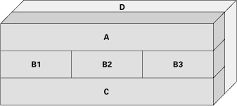
Many architectures that are described as layered look something like Figure 2.22. This type of notation could mean one of two things: (1) Modules in D can use modules in A, B, or C. (2) Modules in A, B, or C can use modules in D. (Technically, the diagram might mean that both are true, although this would arguably be a poor layered architecture.) The creator of the diagram must specify which usage rules pertain. A variation like this makes sense only for single-level usage rules in the main stack, that is, when A can use only B and nothing below. Otherwise, D could simply be made the bottommost layer in the main stack, and the “sidecar” geometry would be unnecessary.
Figure 2.22 Layers with a “sidecar.” The key should make clear what is allowed to use and be used by software in the box on the side.

In some cases, the layered architecture is depicted as a three-dimensional figure, to represent a layer that is accessible to all other layers, as shown in Figure 2.23.
Figure 2.23 Three-dimensional layered diagram trying to show that layer D can be used by all other layers. The picture could just as well be showing that D can use all other layers. The ambiguity should be resolved by an annotation, or in the key.
Such layers on the side often represent utility libraries or platform services (such as the operating system or runtime environment).
Size and Color
Sometimes layers are colored to denote which team is responsible for them or to denote another distinguishing feature. Sometimes layers use different colors just to improve readability. Size is sometimes used to give a vague idea of the relative size of the modules constituting the various layers. If they carry meaning, size and color should be explained in the key accompanying the layer diagram.
UML
UML has no built-in primitive corresponding to a layer. However, layers can be represented in UML as stereotyped packages, as shown in Figure 2.24. A package is a general-purpose mechanism for organizing elements into groups, and it suits the notion of layers. The allowed-to-use relation can be a stereotyped dependency between layer packages.
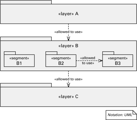
Figure 2.24 Documenting segmented layers in UML. If segments in a layer are allowed to use each other, then <<allowed to use>> dependencies must be added among them as well.
![]()
Appendix A discusses how to use UML classes and packages to represent layers and more.
Access dependencies are not transitive. If package 1 can access package 2 and package 2 can access package 3, it does not automatically follow that package 1 can access package 3.
2.4.5 Relation to Other Styles
Layer diagrams are often confused with other architecture styles when information orthogonal to the allowed-to-use relation is introduced without conscious decision.
1. Module decomposition. Layers in a layered view and modules in a decomposition view are always related but almost never correspond one-to-one with each other. A layer may comprise more than one module. Two submodules of a module may be part of different layers. In any case, you should provide a mapping between layers and the modules in the decomposition view. If a module occurs in more than one layer, you can indicate this by using colors or fill patterns, as in Figure 2.25.
Figure 2.25 A diagram showing layers and modules from a decomposition view from the A-7E software architecture
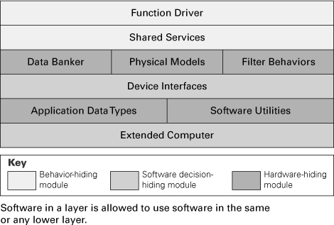
In this example, once again borrowing from the A-7E architecture described previously, the mapping between layers and modules is not one-to-one. In this architecture, the criterion for partitioning into modules was the encapsulation of likely changes. The shading of the elements denotes the coarsest-grain decomposition of the system into modules; that is, Function Driver and Shared Services are both submodules of the Behavior Hiding module. Hence, in this system, layers correspond to parts of highest-level modules. It’s also easy to imagine a case in which a module constitutes a part of a layer.
![]()
Section 2.1.6 has more information about the module decomposition in the A-7E avionics system.
2. Tiers. Layers are often confused with the tiers in a multi-tier architecture. Layers are not tiers. The layered style shows groupings of implementation units and hence is a kind of module style. The multi-tier style is a component-and-connector style because tiers congregate runtime components.
![]()
Section 4.6.2 discusses tiers.
3. Module “uses” style. Because layers express the allowed-to-use relation, there is a close correspondence to the uses style. Of course, no uses relation is allowed to violate the allowed-to-use relation. If incremental development or the fielding of subsets is a goal, the architect will begin with a broad allowed-to-use specification. That specification gives the guidelines for designing with actual uses relations any subset of interest.
![]()
The uses style is covered in Section 2.2.
![]()
See “Perspectives: Using a DSM to Maintain a Layered Architecture” on page 101, in this chapter, for a description of how layered architectures can be identified in a DSM based on existing code.
2.4.6 Examples Using the Layered Style
UNIX System V
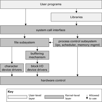
A classic layered design is the UNIX System V operating system, as shown in Figure 2.26. The lower layers form the system kernel; top layers are user programs or libraries that access the kernel through system calls. The system call interface layer isolates the kernel implementation details and provides a virtual machine to user programs. The file subsystem is responsible for managing files (devices are treated as files), administering free space, controlling access, and reading/writing data. The process control subsystem is responsible for process scheduling, interprocess communication, process synchronization, and memory management. The hardware control layer is responsible for handling interrupts and communicating with the machine.
Figure 2.26 The primary presentation of a layered view of the UNIX System V operating system implementation (adapted from Bach 1986)
![]()
This is the approach of stratified design, the notion that a complex system should be structured as a sequence of levels that are described using a sequence of languages. Each level is constructed by combining parts that are regarded as primitive at that level, and the parts constructed at each level are used as primitives at the next level.
—H. Abelson and G. Sussman, Structure and Interpretation of Computer Programs (1996)
This design is presented in Chapter 2 of the classic book by Maurice Bach, The Design of the UNIX Operating System (Bach 1986), where a candid observation is made: “The diagram serves as a useful logical view of the kernel, although in practice the kernel deviates from the model because some modules interact with the internal operations of others.” All such exceptions should be noted in your documentation.
Java EE Application
Figure 2.27 is the primary presentation of the layered view of a set of integrated, multi-tier, Web-based applications that use the Java EE platform. All user operations in these applications follow this layered design. The topmost layer has presentation classes, which are servlets and JavaServer Faces (JSF) action classes. Servlet and JSF are Java component technologies for developing Web components. The second layer has controller classes, which implement the sequence of steps to carry on the functionality of a use case. An example of a controller class is CtlRetrievePtoDays. Controller classes interact with business service classes, which encapsulate the core business logic associated with domain objects. An example of a service class is SvcFullTimeEmployee. The lowermost layer has data access objects. These modules handle all interaction with the relational database.
Figure 2.27 Part of the layered view of a set of Java EE applications. The top layer has servlets and JSF action classes responsible for the user interface. Controller classes handle the user operations by interacting with business service classes. Access to the database is done in the lowermost layer with the data access objects. Sidecar layers contain DTOs and POJOs that are used by the other layers to hold and transfer data.

There are two sets of auxiliary modules that are presented as sidecar layers. On the left are presentation data transfer objects (DTOs). They are simple classes that contain basic attributes corresponding to data elements required in different user screens. The right sidecar layer has the corporate DTOs and plain old Java objects (POJOs). Like presentation DTOs, these classes have a set of attributes to hold data. In this design, DTOs have attributes required by a particular transaction, whereas POJOs correspond to data entities stored in the database.
The key drivers for this layered design are modifiability and portability, which is achieved with separation of concerns. On top is the presentation layer. Changes to the user interface are addressed in that layer. If the technology used to implement the UI has to change from servlet and JSF to, say, Google Web Toolkit and Flash, this layer has to be rewritten, but the other layers should remain unchanged. The second layer implements the logic to handle the user actions by wiring the calls to services in the third layer, which is the core business logic layer. The bottom layer isolates database access operations and also enhances portability. If the application is migrated to a different database management system with a different SQL dialect, all modifications required would be confined to that layer.
Perspectives: Calling Higher Layers
We have been emphatic in saying that upward uses invalidate layering. We made allowances for documented exceptions but implied that too many of those would get you barred from the Software Architect’s Hall of Fame.
Seasoned designers, however, know that in many elegantly designed layered systems, all kinds of control and information flow upward along the chain of layers, with no loss of portability, reusability, modifiability, or any of the other qualities associated with layers. In fact, one of the purposes of layers is to allow for the “bubbling up” of information to the units of software whose scope makes them the appropriate handlers of the information. One approach to error handling illustrates this upward flow. Suppose that we have a simple three-layer system, as in Figure 2.28. Say that program PA in A uses program PB in B, which uses program PC in C. If PC is called in a way that violates its specification, PC needs a way to tell PB, “Hey! You called me incorrectly!” At that point, (1) PB can either recognize its own mistake and call PC again, this time correctly, or take another action; or (2) PB can realize that the error resulted because it was called incorrectly—perhaps it received bad data—by PA. In the latter case, PB needs a way to tell PA, “Hey! You called me incorrectly!”
Figure 2.28 Layered design showing programs inside and their usage dependencies

Callbacks are a mechanism to manifest the protestation. We do not want PC written with knowledge about programs in B or PB written with knowledge about programs in A, as this would limit the portability of layers C and B. Therefore, the names of higher-level programs to call in case of error are passed downward as parameters. Then the specification for, say, PB includes the promise that in case of error, it will invoke the program whose name has been made available to it.
Other situations where callbacks can be used include:
• When PA uses PB to obtain data to present in the user interface but PA also wants PB to announce future changes to the data. In other words, PA subscribes to events that can be emitted by PB and provides to PB the name of the operation that will handle the events.
• When PA uses PB and the interaction is asynchronous, but PA needs to receive a response once PB is done processing the request. In this case PA provides PB the name of the operation to call.
So there we have it: data and control flowing downward and upward in an elegant error-handling scheme that preserves the best qualities of layers. So much for our prohibition about upward uses. Right?
Wrong. Upward uses are still a bad idea, but the scheme we just described doesn’t have any. It has upward data flow and upward invocation but not uses. The reason is that once a program calls its error handler, its obligation is discharged. The program does not use the error handler, because its own correctness depends not a whit on what the error handler does. This is how the callback mechanisms, built in to some programming languages, work and still allow true layered systems to be written in those languages.
Although this may sound like a mere technicality, it is an important distinction. Uses is the relation that determines the ability to reuse and to port a layer; “calls” or “sends data to” is not. Architects need to know the difference and need to convey the precise meaning of the relations in their architecture documentation.
—P.C. and P.M.
Perspectives: Using a DSM to Maintain a Layered Architecture
Tools based on the dependency structure matrix claiming to be the solution to managing complexity in large software projects have recently been capturing the attention of program analysts and software architects. The DSM concept has been adopted for use in software engineering from its origins with Donald Steward as the Design Structure System (Steward 1981), which he devised in 1967 to help manage complexity in the nuclear power industry. Over the past 15 years the DSM has been used in a wide variety of industries to aid in systems engineering and analysis as well as project planning and management.
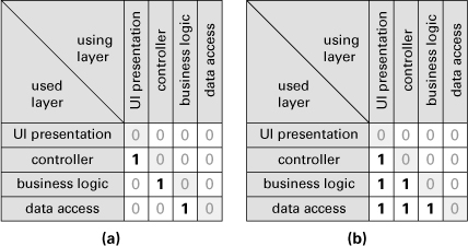
When layer A depends on layer B and layer B depends on layer A, there is a codependence between these two layers, a situation that is forbidden in a layered architecture. In a DSM, circular dependencies are immediately visible as marked cells on both sides of the matrix’s diagonal. A layered architecture is clearly discernable because the corresponding DSM is a lower triangular matrix (that is, one in which all the marked cells are below the diagonal). For example, consider the layered architecture in Figure 2.29. The key indicates that a layer is allowed to use only the next lower layer, so it’s a strictly layered design. The corresponding DSM is shown in Figure 2.30(a). If a layer were allowed to use any lower layer, the DSM would be similar to Figure 2.30(b). When cells above the diagonal are marked, the architect can see the circular dependency and focus on what to change to reach the goal of a layered architecture.
Figure 2.29 Simple layered architecture
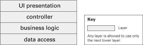
Figure 2.30 DSM showing (a) strictly layered design and (b) layered design
In practice, layered designs are more complex. Figure 2.31 shows the layered design that was introduced in Figure 2.27, now with Java packages added for each layer. The DSM for this design is shown in Figure 2.32. In a DSM tool, the architect can mark the dependencies that violate the layered design: the highlighted cells above and below the diagonal in Figure 2.32. During the implementation of the system, the tool can create a DSM from the code and highlight any violations. If other constraints on interdependencies have been indicated by the architect, those will also be visible using the DSM representation. With good tool support, continuous integration builds can be subjected to DSM analysis, and architecture violations can be caught immediately. DSM tools also generally allow the user to perform “what-if” analysis by simulated restructuring of the system, providing immediate insight into the impact that a suggested change would have on the system’s structure.
Figure 2.31 Layered design showing Java packages for each layer
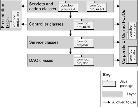
Figure 2.32 DSM for a layered design. The highlighted cells above and below the diagonal represent dependencies that are not allowed

—J.S. and P.M.
2.5 Aspects Style
2.5.1 Overview
The aspects style is a module style used to isolate in the architecture the modules responsible for crosscutting concerns.
![]()
If you haven’t documented a commonality, it isn’t likely to be one by the time you get done implementing.
—D. L. Parnas
When we implement software modules in general, the business logic code ends up intermixed with code that deals with crosscutting concerns. For example, if you’re writing a bank automation system, there may be modules such as Account, Customer, and Atm. The Account module ideally would contain only the code to deal with the bank account business logic (open/close account, deposit, withdraw, transfer, and so on). But in practice we have to add code to handle crosscutting concerns, such as access control, transaction management, and logging.
The aspects style prescribes that the modules responsible for the crosscutting functionality should be placed in one or more aspect views. These modules are called aspects, based on the terminology introduced by aspect-oriented programming (AOP). The aspect views should contain information to bind each aspect module to the other modules that require the crosscutting functionality.
![]()
See “Coming to Terms: Aspect-Oriented Programming” on page 107, in this chapter.
The aspects style is particularly useful when you plan to use AOP in the implementation. However, it’s also applicable when crosscutting functionality will be implemented in traditional ways through class inheritance and interfaces, macro insertion, dependency injection, utility libraries, or other alternatives. The goal of designing and implementing crosscutting concerns in separate aspect modules is to improve modifiability of the modules that deal with the business domain functionality.
2.5.2 Elements, Relations, and Properties
Table 2.5 summarizes the characteristics of the aspects style. The elements in the aspects style are aspect modules. As mentioned in Section 2.5.1, an aspect is a special type of module introduced by AOP. It contains the crosscutting code that affects other specific modules in the system.
Table 2.5 Summary of the aspects style
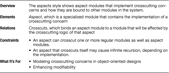
The relation found in the aspects style is usually called crosscuts. An aspect crosscuts a module if the aspect contains crosscutting functionality that will affect the module. An aspect may contain the same properties of a regular module. In addition, it may contain a property that describes what target modules are affected by that aspect; in AOP terms, this property is called pointcut specification.
2.5.3 What the Aspects Style Is For
The aspects style can be used to model the implementation of crosscutting concerns. It promotes modifiability by increasing modularity and avoiding the tangling of crosscutting functionality and business domain functionality.
2.5.4 Notations for the Aspects Style
UML
Although UML does not have built-in symbols for aspects, it is a common choice for aspect views. In UML aspect modules are usually represented as stereotyped classes in a class diagram, as shown in Figure 2.33. Especially when the target implementation platform supports AOP, showing aspect modules as stereotyped classes makes sense because aspects are structurally similar to classes: they may contain attributes and operations, and they may extend another aspect in an inheritance relation.
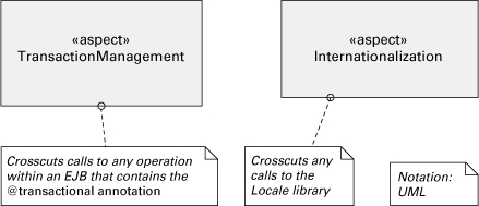
Figure 2.33 Aspect modules are often represented in UML as classes with stereotype <<aspect>>.

The crosscut relation could be represented as a stereotyped dependency going from the aspect to each module it crosscuts. However, this alternative does not scale: by definition an aspect provides crosscutting functionality, and hence it may crosscut too many modules. Drawing a line between the aspect module and each of the crosscut modules is impractical in nontrivial systems and would clutter the diagrams. A better alternative is simply to omit the crosscut relation from the diagrams. Instead, just add a comment to the aspect module to characterize (in natural language or in a formal syntax) what other modules this aspect crosscuts. Figure 2.34 shows an example. Not showing the crosscut relation in the diagram actually makes sense because in an AOP implementation, the developer doesn’t have to identify each target class for a given aspect. The architecture representation should not be more detailed than the implementation!
Figure 2.34 Instead of trying to draw a line from each aspect to every module it crosscuts, we simply add a comment box that characterizes what modules will be crosscut.
2.5.5 Relation to Other Styles
In general, aspects allow inheritance. The aspects style may be combined with the generalization style when we want to show a hierarchy of aspects.
2.5.6 Examples Using the Aspects Style
Figure 2.35 is from the aspects view of an application called IkeWiki. The design prescribes the use of aspects for transaction management, exception handling, authorization check, and enforcement of architecture constraints. Drawing a line for each crosscut relation would be impractical, so the architect opted simply to indicate with comments what other modules should be crosscut by each aspect.
Figure 2.35 Primary presentation for the aspects view of the IkeWiki application. This Java EE application implemented with the Spring framework and Google Web Toolkit uses aspects for some crosscutting concerns. The TransactionManagement aspect makes sure all requests received by the server will close the transaction and release database resources properly, performing a rollback when an exception occurs. The ExceptionHandling aspect has code to log the error to the database, send e-mail notification if applicable, and wrap the exception with a proper user message to be displayed by the client application. This aspect is woven into server-side classes that are either threads or entry points to process HTTP requests. The AuthorizationCheck aspect is used to check if the current user has permission to execute a specific method. The Enforcement aspect is different from the others. It doesn’t exactly implement a crosscutting concern, but rather it scans the source code at compile time looking for violations of the layered design, as well as violations of several coding policies.

Coming to Terms: Aspect-Oriented Programming
Aspect-oriented programming is an evolutionary implementation paradigm that complements object-oriented programming and facilitates the implementation of crosscutting concerns. AspectJ is probably the most widely known AOP package. Other implementations include Spring AOP, JBoss AOP, AspectC++, and Aspect#.
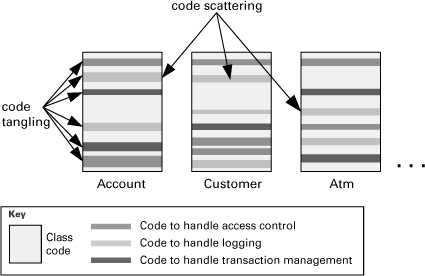
Suppose the bank automation example is implemented using a regular object-oriented language. The solution would contain classes such as Account, Customer, and Atm. In these classes, the code to handle crosscutting concerns such as logging or transaction management is tangled with the business logic code, making the classes more difficult to maintain. Moreover, the lines of code found in class Account to handle transaction management are very similar if not equal to the lines of code that handle the same concern in Customer, Atm, and other classes. The code for a particular concern is scattered across several classes; that poses a modifiability problem. Suppose you need to change the signature of a method used for logging. You’ll need to change the corresponding lines of code in all classes where logging is needed. Code tangling and code scattering in traditional object-oriented applications is notionally represented in Figure 2.36.
Figure 2.36 The traditional object-oriented implementation of a bank automation system would have several classes where the business logic is tangled with code that handles crosscutting concerns, such as access control, logging, and transaction management. In addition, the code that handles a particular crosscutting concern is repeated and scattered across several classes.
AOP brings an ingenious solution to improve modularity and resolve the code tangling and code scattering problems. The crosscutting code is factored out from the classes and placed in a special module called aspect, as represented in Figure 2.37. An aspect has two important parts: advices and pointcut specifications. Advices contain the code for the crosscutting concerns. Such code will be injected at certain points (called join points) of the classes through a process called weaving, carried on by the AOP compiler. The pointcut specifications contain declarations that map to specific sets of join points in the target classes. In the aspect code, advices are associated to pointcut specifications to let the AOP compiler know where exactly each advice code will be injected in the target classes.
Figure 2.37 In the aspect-oriented implementation of the same bank automation system, the classes don’t contain code for logging, access control, transaction management, and other crosscutting concerns. The code to handle these concerns is now inside aspect modules. Classes such as Account, Customer and Atm contain the business logic only. The AOP compiler will use the weaving process to insert the code inside aspects at the locations in the classes where it’s needed.

AOP is the programming component of the larger aspect-oriented software development (AOSD) movement, which strives to factor out otherwise-redundant commonality in all kinds of software activities, including requirements engineering, design, and testing.
2.6 Data Model
2.6.1 Overview
Data modeling is a common activity in the software development process of information systems. The output of this activity is the data model, which describes the static information structure in terms of data entities and their relationships. For example, in a banking system, entities typically include Account, Customer and Loan. Account has several attributes, such as account number, type (savings or checking), status, and current balance. A relationship may dictate that one customer can have one or more accounts, and one account is associated to one or two customers. The data model is often represented graphically in entity-relationship diagrams (ERDs) or UML class diagrams.
The first draft of an architecture view typically has very little detail. Over time, as design decisions are made, the view is elaborated until the architect considers there’s enough information captured in that architecture view. The same thing happens with the data model. Data modeling spans the evolution of the high-level model that displays the data entities in a given business domain into a model that shows details of how the data is stored, for example, in a relational database management system. As a result, different organizations focus the modeling and documentation effort on different stages of the data model evolution. Thus organizations sometimes use qualifiers to the data model to distinguish these stages. Examples of qualifiers include:
• Conceptual. The conceptual data model abstracts implementation details and focuses on the entities and their relationships as perceived in the problem domain. Figure 2.38 shows a fragment of a conceptual data model.
Figure 2.38 First draft of a conceptual data model. This and the next two diagrams are fragments of an online order-processing system at different stages.

• Logical. The logical data model is an evolution of the conceptual data model toward a data management technology (such as relational databases). It is typically the subject of normalization (see Section 2.6.2). Figure 2.39 shows an example of a logical data model.
Figure 2.39 Logical data model that has evolved from the conceptual data model in Figure 2.38

• Physical. The physical data model is concerned with the implementation of the data entities. It incorporates optimizations that may include partitioning or merging entities, duplicating data, and creating identification keys and indexes. For example, in Figure 2.40 a column named total-Price was likely added to the entity Order as a performance optimization, since the total price could also be obtained by reading all order items and adding up their prices.
Figure 2.40 Physical data model that was created by adding implementation details and optimizations to the logical data model in Figure 2.39

In an early stage, the architecture documentation may contain the data model with the key entities and important relationships. Later on, this initial model is superseded by the detailed model approved by the data administrators.
2.6.2 Elements, Relations, and Properties
Table 2.6 summarizes the characteristics of the data model style.
Table 2.6 Summary of the data model style

![]()
See “Coming to Terms: Entity” on page 118, in this chapter.
The elements in a data model are called data entities or simply entities. Any distinguishable object that contains information to be stored or represented in the system can be an entity.
Properties of entities may include:
• Name of the entity.
• Description of the meaning and significance of the entity.
• List of data attributes of the entity. For example, a Car entity may have attributes year, manufacturer, model, mileage, price, and license. Each attribute may have properties, such as data type, size, and whether it’s a required attribute or not.
• The attribute (or attributes) used to uniquely identify an entity (that is, the primary key).
• Whether an entity is weak. A weak entity, also known as a dependent entity, depends on the existence of another entity to exist. For example, an OrderItem requires the existence of a PurchaseOrder in Figure 2.40.
• Constraints and invariants on the values of individual or combined attributes. For example, “Returning date cannot be prior to arrival date.”
• Rules that will be used to grant permissions to users or user groups to access the entity.
• Expected number of entity instances and growth rate.
Other properties concern the physical data model and are specific to the target implementation platform of the data model. Examples include:
• List of attributes that should be indexed to optimize access time.
• List of attributes that should be encrypted or compressed.
• Whether the entity should become a database view instead of a table. A view is a virtual table that is defined by a SQL query command on one or more tables.
• Whether the entity should become a materialized view, which means it will be implemented as a database table that stores a subset of the data copied from a master table. Like a regular view, the subset is defined by a query command.
• List of database triggers that will be implemented for that entity. A trigger is a special procedure that is automatically executed by the database management system when data is inserted, updated, or deleted.
There are three types of relations found in data models:
• Relationship. Used to designate a logical association between entities. It is usually qualified by the cardinality of the participant entities: one-to-one, one-to-many, or many-to-many. In addition, a relationship can be identifying or nonidentifying. An identifying relationship from A to B means that the existence of B depends on the existence of A; that is, the primary key of B contains the primary key of A.
• Generalization/specialization. Indicates an is-a relation between entities. For example, entity Insurance is a generalization of different types of insurances; at the same time, entities Car Insurance and House Insurance are specializations of entity Insurance.
• Aggregation. An abstraction that turns a relationship between entities into an aggregate entity (Smith and Smith 1977). For example, a relationship between a patient, a physician, and a date can be abstracted as an aggregate entity called Appointment. In practice, this relation is rarely used.
![]()
For an explanation of the normalization technique and description of the various normal forms, refer to the classic book by C. J. Date, An Introduction to Database Systems (1999).
Conceptually, there are no topological constraints with respect to the relations in a data model. However, the database normalization technique imposes restrictions on the data model based on the dependencies between entity attributes. Normalization is used by data administrators to avoid duplication of information, in order to safeguard the consistency (integrity) of the data. Figures 2.41 and 2.42 show an example of normalization.
Figure 2.41 Entity ProjectAssignment before normalization, along with sample data (adapted from Ponniah 2007). The attributes that uniquely identify a project assignment (that is, the primary key) are EmpId and ProjNo.

Figure 2.42 Data model for ProjectAssignment after normalization. One of the rules of normalization is that non-key attributes should have functional dependencies to the whole primary key only. Attribute ProjDesc has a functional dependency to ProjNo, which is not the whole primary key. After this and other violations of the normalization rules were fixed, this is the resulting data model diagram.

2.6.3 What the Data Model Is For
The data model facilitates stakeholder communication during domain analysis and requirements elicitation. But foremost, the data model is the blueprint for the implementation of the data entities, for example, in a relational database.
A carefully created data model also helps to achieve performance requirements in a software system. In data-centric applications, access to the data usually represents a significant amount of the time to process user requests. The architect and the data administrator should understand what kinds of data access operations will be more critical to the system and what their performance requirements are. Driven by these requirements, denormalizations, optimizations, and other design decisions are applied to the data model, aiming at improved system performance. Examples of these design decisions include:
• Merging two entities to avoid an expensive outer join or union operation in a query
• Adding a derived attribute to avoid scanning an entire data table to obtain the derived value
• Creating an index on attributes that are often parameters in a query
• Changing the granularity (such as table row or page) and type (such as optimistic) of locks on certain entities to avoid contention and deadlocks
After the software system is implemented, even when the data model is carefully created, it’s common to find performance bottlenecks in data access operations. To remove these bottlenecks, the data model comes in handy once again, in a task called query optimization.
In information systems, the data model is essential input to modifiability analysis. To analyze the impact of required modifications to a system, one cannot look exclusively at the code structure. Many modifications require altering the data model and hence its physical implementation. Modifications to the data model can be costly, as they may require changing the code of multiple applications that share the same data. A simple change such as making a certain attribute of an entity mandatory (for example, requiring a customer’s date of birth) may require changes to all screens and functions that allow creating or updating that information. Versioning and redeployment of applications is more complicated when data model changes are involved. Moreover, larger data model modifications, such as merging with the data model of a legacy system, may also require the implementation of extract, transform, and load (ETL) operations to fix the data itself. Indeed, the data model is an important input to data warehouse projects and to the integration of data schemas required by some business partnerships (for example, an airline company needs to share data with a car rental company).
The data model is an architecture view that should ideally be created with a thorough understanding of incremental development plans, future extensions, and integration of data across information systems. Data is a valuable asset, and the existence of an enterprise data model and a data administration group helps to enforce data integrity. If a new system needs to retrieve sales information, the enterprise data model may already contain that information. The architect of the new system may not be aware of the data entities that hold sales information, but the data administrator should and can point out those entities instead of creating new ones in the database. Disparate, redundant data contribute to poor data quality.
![]()
Data integrity refers to the consistency and accuracy of the data shared across all applications in a system.
Based on the data model, data modeling tools can generate scripts to create the physical database. Some tools can also generate application code to access the data tables, classes to hold the data, forms for end users to enter data, message schemas, and simple reports.
Finally, the data model can help application developers to write code to access the database. It is easier to understand an entity-relationship diagram than to browse through the table creation commands or the database management system dictionary.
2.6.4 Notations for the Data Model Style
The data model can be described graphically using informal or semiformal visual notations that include:
• Peter Chen’s entity-relationship diagram notation (Chen 1976)
• Crow’s foot entity-relationship diagram notation
• IDEF1X
• UML class diagram
The first three notations are ERD variations, and the last one is the UML alternative to ERD. Crow’s foot and UML class diagrams are more widely used in industry and more commonly supported by tools.
Crow’s Foot ERD Notation
One of the most popular ERD notations for relationships uses lines with special symbols at each end to indicate cardinality. These symbols include a dash (indicating one), a ring (indicating zero), and a crow’s foot (indicating many). The crow’s foot ERD notation was initially used in the 1980s by Richard Barker (1990), as well as in the Information Engineering approach developed by James Martin and Clive Finkelstein (1981). The symbology found in today’s tools provides slight variations on Baker’s original notation and the Information Engineering notation. Figure 2.43 shows an example.
Figure 2.43 Data model (simplified) of a human resource system using crow’s foot ERD notation
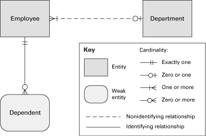
UML
The data model can be represented as a UML class diagram, where the classes correspond to data entities. The attribute compartment lists the entity attributes, and the operation compartment is empty. UML associations represent the relationships between entities and the multiplicity intervals shown at both ends of the association lines (for example, “1..*”) indicate the cardinality of the relationship. Figure 2.44 shows an example.
Figure 2.44 Data model (simplified) of a human resource system shown as a UML class diagram

UML was originally created for object-oriented modeling, not for data modeling. Therefore, it doesn’t provide built-in mechanisms for indicating primary keys, weak entities, or foreign keys. In addition, class diagrams are more flexible than ERDs. For example, a class Order may include a list of items as an attribute, whereas in an ERD, Item would naturally be a separate entity. Some constraints are needed in order to use UML class diagrams as an ERD alternative.
![]()
The Object Management Group has a draft specification for an Information Management Meta-model that contains a UML 2 profile for entity-relationship modeling. It is available online at omgwiki.org/imm.
2.6.5 Relations to Other Styles
The entities in the data model are intrinsically connected to some of the modules in other module views, especially the modules that contain the in-memory representation of the data. In object-oriented systems that use a relational database to store data, we typically find classes that correspond to the persisted entities. The mapping is not always one-to-one, because the relational paradigm is fundamentally different from the object-oriented paradigm. This problem is known as the object-relational impedance mismatch (Ambler 2006) and is addressed by object-relational mapping (ORM) tools and frameworks, such as Hibernate for Java and LLBLGen for Microsoft .NET.
The architect may find it useful to indicate what modules (in a module view), what components (in a component-and-connector view), or even what use cases from the functional requirements do use which data entities. Such mapping of the data model to other views can be recorded as a table, as described in Section 10.2. Moreover, the architect can indicate whether each element creates, reads, updates, or deletes data (CRUD, for short) from each data entity. This generic mapping can be represented as a CRUD matrix.
![]()
Mapping between views is discussed in Section 10.2.
The data model describes the structure of data entities and relationships that will typically be deployed to a shared-data-store component such as an Oracle database. Data stores are typically depicted in a shared-data view of the architecture, along with the other runtime components that access them. Also, a deployment view typically shows what machine(s) the data stores are allocated to. Documenting the mapping of entities in a data model to different data stores and respective machines is especially useful when the solution uses distributed or replicated databases.
![]()
The shared-data style is covered in Section 4.5.1.
![]()
The deployment style is described in Section 5.2.
2.6.6 Examples
Figure 2.45 shows the data model reconstructed and adapted from the Microsoft .NET Pet Shop application (Microsoft 2002), a Web store that keeps a catalog of pets and takes purchase orders from registered Web users. The data is persisted in a relational database. The majority of the functionality consists of retrieving, creating or updating the data elements shown in the data model.
Figure 2.45 Data model for the Pet Shop application using Information Engineering crow’s foot ERD notation

2.7 Summary Checklist
• A decomposition view shows how responsibilities are allocated across modules and submodules.
• A uses view shows how modules depend on one another. This view helps achieve incremental development and is especially suitable for performing change-impact analysis.
• A generalization view relates modules by showing how one is a generalization or specialization of the other. This view is widely used in object-oriented systems, where inheritance is used to exploit commonality among modules.
• A layered view divides a system into groups of modules that provide cohesive responsibilities. These groups are called layers and relate to each other unidirectionally by the allowed-to-use relation. A layered design helps a system achieve portability and modifiability.
• An aspects view shows special modules called aspects, which are responsible for crosscutting concerns. This view is particularly useful if the system implementation is going to use AOP.
• A data model view describes the structure of the data used in the system in terms of data entities and their relationships. It guides implementation and helps to improve performance and modifiability in data-centric systems.
2.8 Discussion Questions
1. Can you think of a system that cannot be described using a layered view? If a system is not layered, what would this say about its allowed-to-use relation?
2. How does a UML class diagram relate to the styles given in this chapter? Does that diagram show decomposition, uses, generalization, or another combination?
3. We consciously chose the term generalization to avoid the multiple meanings that the term inheritance has acquired. Find two or three of these meanings, compare them, and discuss how each is a kind of generalization. (Hint: You may wish to consult books by Booch and Rumbaugh, respectively.)
4. Suppose that your system will include commercial off-the-shelf (COTS) software modules. In which module views might you show them and why?
5. Would you create a data model using an entity-relationship notation for a system that will not contain a database? In what situations and why?
6. Crosscutting concerns have been implemented in object-oriented systems without using AOP constructs. Would you create an aspect view for your system if your implementation will not use AOP? Would you use aspect modules in your design in this case?
7. The two layered diagrams in Figure 2.46 are from real systems. The first is called the ECMA “toaster model,” which has slots for pluggable tools. The second is the layered architecture of the OSGi framework. How is the allowed-to-use relation represented in these diagrams? How would you create the key to each diagram so that any ambiguity in the notation is removed?
Figure 2.46 ECMA “toaster model” (left) and OSGi framework layered design (right)
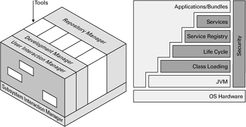
2.9 For Further Reading
Most of the styles in this chapter can be traced to a foundational paper in the annals of the software engineering literature. An architect interested in the roots of the discipline may find the original ideas refreshing in their simplicity and purposefulness. These papers, seen as a group, express the then-revolutionary idea that there is more to a computer program than getting the right answer: how it is structured also matters.
In 1968, Edsger Dijkstra wrote about designing an operating system as a set of abstract virtual machines, giving us the concept of layers (Dijkstra 1968). David Parnas showed how decomposing a system into modules based on likely changes, as opposed to steps in the processing, resulted in systems vastly easier to modify (Parnas 1972). Parnas also introduced the uses relation and showed how it could lead to software that was easy to extend or to develop incrementally (Parnas and Weiss 1979).
In the 1960s the fundamental concepts of object-oriented programming, including objects, inheritance, and dynamic binding, were invented by Ole-Johan Dahl and Kristen Nygaard at the Norwegian Computing Center in Oslo (Nygaard and Dahl 1981). The concepts were introduced in the programming language Simula-67, which, although never widely used itself, laid the foundation for the development of popular object-oriented languages such as Smalltalk and C++. In 1986–1987, two widely influential papers by Alan Snyder and Barbara Liskov, respectively, tied together two concepts that had been drifting apart: inheritance and encapsulation (Snyder 1986, Liskov 1987). Liskov in particular argued convincingly that undisciplined inheritance that violated objects’ abstractions was harmful. Between them, they set the object-oriented community on its present path.
A software engineering demonstration project that paid special attention to the use of separate architectural structures was the A-7E avionics system built by the U.S. Navy in the 1980s. A case study is presented in the book by Bass, Clements, and Kazman (2003). The example employs decomposition (using information hiding as the criterion [Parnas, Clements, and Weiss 2001]), layers, and uses, and it shows how a subset is built from the uses relation.
The authoritative source of information about the UML language and notation is the specification published by the Object Management Group (OMG 2009), which at the time of writing is on version 2.2. However, there are many UML books that are far more digestible. Two valuable references are The Unified Modeling Language User Guide, by Booch, Rumbaugh, and Jacobson (2005), and UML Distilled, by Martin Fowler (2003). UML classes, packages, and their relations are especially relevant to module styles.
The seminal paper on aspect-oriented programming was written by Gregor Kiczales and colleagues at Xerox PARC (Kiczales et al. 1997). It describes the concepts and terminology that were later used to create AspectJ and other AOP languages. The second edition of the book by Ramnivas Laddad (2008) is an excellent guide to AspectJ and provides a nice introduction to AOP. Recently, aspect orientation has been investigated in the realm of domain analysis, requirements engineering, and software architecture. Resources about the use of aspects in early phases of software development can be found at early-aspects.net.
Data modeling is a well-established discipline. Entity-relationship modeling was originally proposed by Peter Chen (1976). In addition to Chen’s original paper, the book by C. J. Date (2003) has been an important reference to relational theory, normalization, and data modeling since the publication of the first edition in 1975.