
5. Allocation Views and a Tour of Some Allocation Styles

In this chapter, after a brief overview of allocation views, we look at these aspects of allocation views and styles:
• Deployment style
• Install style
• Work assignment style
• Other allocation styles
5.1 Overview
Software elements in a software architecture interact with nonsoftware elements in the environment in which the software is developed, deployed, and executed. Computing and communication hardware, file management systems, and development teams all interact with the software architecture. Because of this, the “set of structures needed to reason about the system” (from our definition of software architecture given in the prologue) includes structures that show the relations between software and nonsoftware elements. It is through the mapping between the software architecture and the hardware that the performance of the system can be analyzed; it is through the mapping between the software architecture and a file structure that the management of the system in production can be done; and it is through the mapping between the software architecture and the team structure that project management activities can proceed.
![]()
You can think of an allocation view as the result of combining a software architecture view with a view from a different kind of architecture—for example, a hardware architecture or an organizational architecture. Section 6.6 describes techniques for combining otherwise-separate views, and why you might want to do so.
These structures have a first-class place in the Views and Beyond approach, and this chapter focuses on the views and styles that represent them. Allocation views present a mapping between software elements (from either a module view or a component-and-connector [C&C] view) and nonsoftware elements in the software’s environment.
We begin by considering the most general form of the mapping between the software architecture and its environment. We then identify three common allocation styles, as shown in Figure 5.1.
• The deployment style describes the mapping between the software’s components and connectors and the hardware of the computing platform on which the software executes.
![]()
These are not the only allocation styles; many others are possible and useful. Examples can be found in Section 5.5 and “Perspectives: Coordination Views,” on page 209, in this chapter.
• The install style describes the mapping between the software’s components and structures in the file system of the production environment.
• The work assignment style describes the mapping between the software’s modules and the people, teams, or organizational work units tasked with the development of those modules.
Figure 5.1 Three allocation styles are deployment (mapping software architecture to the hardware of the computing platform), install (mapping it to a file system in the production environment), and work assignment (mapping it to the teams in the development organization).

Table 5.1 summarizes the characteristics of the allocation styles. The elements of allocation styles are software elements plus environmental elements. Examples of environmental elements are a processor, a disk farm, a file or folder, or a group of developers. The software elements come from a module or C&C style.
Table 5.1 Summary of the characteristics of the allocation styles

The relation in an allocation style is the allocated-to relation. We usually talk about allocation styles in terms of a mapping from software elements to environmental elements, although the reverse mapping would also serve the same purposes. A single software element can be allocated to multiple environmental elements, and multiple software elements can be allocated to a single environmental element. If these allocations change over time, during either development or execution of the system, then the architecture is said to be dynamic with respect to that allocation.
Software elements and environmental elements have properties in allocation styles. The specific properties you should include in an allocation view will, as always, depend on the purpose of that view. The usual goal of an allocation view is to compare the properties required by the software element with the properties provided by the environmental elements to determine whether the allocation will be successful or not. For example, to ensure a component’s required response time, it has to execute on (be allocated to) a processor that provides sufficiently fast execution times, where “sufficiently fast” might be defined in terms of a requirement that an IEEE 754 single-precision floating-point multiply must execute in 50 microseconds. Or a computing platform might not allow a task to use more than 10 kilobytes of virtual memory. In this case, an execution model of the software element in question can be used to determine the required virtual memory usage.
The specific uses and notations for allocation styles are style specific and are covered in their respective sections.
5.2 Deployment Style
5.2.1 Overview
In the deployment style, software elements native to a C&C style are allocated to the hardware of the computing platform on which the software executes. A valid allocation ensures that the requirements expressed by the software elements are satisfied by the characteristics of the hardware element(s).
5.2.2 Elements, Relations, and Properties
Table 5.2 summarizes the characteristics of the deployment style. Environmental elements in a deployment style are entities that correspond to physical units that store, transmit, or compute data. Physical units include processing nodes (CPUs), communication channels, memory stores, and data stores.
Table 5.2 Summary of the deployment style
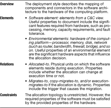
The software elements in this style are typically elements that would be documented in a C&C view. When represented in a deployment view, the software elements are assumed to run on a computer. Therefore, software elements in this style correspond to runtime entities of the computing platform (such as processes, threads, ports, or shared memory).
![]()
Although the deployment style in its general form imposes no topological-form restrictions, specializations (substyles) of the deployment style might. See Section 5.5 for examples.
The typical relation depicted in a deployment view is a special allocated-to form that shows on which physical units the software elements reside at a given moment in time. The relation can be dynamic; that is, the allocation can change as the system executes. In this case, additional relations, such as the following, may be shown:
• Migrates-to. A relation from a software element on one processor to the same software element on a different processor, this relation indicates that a software element can move from processor to processor but does not simultaneously exist on both processors.
![]()
Section 6.4.3 describes how to document dynamism and dynamic architectures.
• Copy-migrates-to. This relation is similar to the migrates-to relation, except that the software element sends a copy of itself to the new processor while retaining a copy on the original processing element.
• Execution-migrates-to. Similar to the previous two, this relation indicates that execution moves from processor to processor but that the code residency does not change. A copy of a process exists on more than one processor, but only one is active at any particular time. The execution of the process “migrates” when the active process is changed.
It is also possible for the allocation to change over time as a result of manual reconfiguration brought about by exercising a variation point built in to the architecture.
![]()
Documenting variation points is discussed in Section 6.4.
The important properties of the elements are the significant hardware features that affect the allocation of the software to the physical units. How a physical unit satisfies a software element requirement is determined by the properties of both. For example, if a software element requires a minimum storage capacity, any environmental element that has at least that capacity is a candidate for a valid allocation.
Moreover, the types of analyses to be performed via a deployment view also determine the particular properties the elements must possess. For example, if a memory capacity analysis is needed, the necessary properties of the software elements must describe memory consumption aspects, and the relevant environmental element properties must depict memory capacities of the various hardware entities.
Below are some environmental element properties relevant to physical units:
• CPU properties. The properties relevant to the various processing elements (such as processor clock speed, number of processors, memory capacity, bus speed, cache size, and instruction execution speed).
• Memory properties. The properties relevant to the memory stores (such as memory size and speed characteristics).
• Disk or other storage unit capacity. The storage capacity and access speed of disk units: individual disk drives, disk farms, and redundant arrays of independent disks (RAIDs).
• Bandwidth. The data transfer capacity of communication channels.
• Fault tolerance. Multiple hardware units may perform the same function, and these units may have a failover control mechanism.
Properties that are relevant to software elements include the following:
• Resource consumption. For example, a computation takes 32,123 instructions always, or at most, or on average, or under nominal (error-free) conditions, and so on.
• Resource requirements and constraints that must be satisfied. For example, a software element must execute in no more than 0.1 second.
• Safety critical. For example, this would be true if a software element must always be running.
The following property is relevant to the allocation:
• Migration trigger. If the allocation can change as the system executes, this property specifies what must occur for a migration of a software element from one processing element to another.
5.2.3 What the Deployment Style Is For
A deployment view is useful for analyzing performance, availability, reliability, and security. Testers use this view to understand runtime dependencies, and integrators use it to plan integration and integration testing. A deployment view may also be used to support cost estimation when evaluating purchasing options for hardware.
Performance is tuned by changing the allocation of software to hardware. Optimal or improved allocation decisions could be those that eliminate bottlenecks on processors or that distribute work more evenly (for example, processor utilization is roughly even across the system). Often performance improvement is achieved by collocating deployment units that require frequent and/or high-bandwidth communications with one another. The volume and frequency of communication among deployable units on different processing elements, which takes place along the communication channels between those elements, is the focus for much of the performance engineering of a system. The architect can employ additional hardware or replace hardware elements with more powerful versions when requirements cannot be met no matter how the allocation is optimized.
Availability and reliability are directly affected by the system’s behavior in the face of faulty or failed processing elements or communication channels. If a processor or a channel can fail without warning, copies of software components can be placed on separate processors. If a warning will precede a failure, then components can be migrated at runtime when a failure is imminent. If every processing element has enough memory to host a copy of every deployable unit, runtime migration need not occur. When a failure occurs, a different copy of the no-longer-available deployable unit becomes active, but no migration of code occurs.
Security and attack resistance are influenced by the configuration of the hardware and the allocation of software to it. Limit the services available on each host to limit exposure. Firewalls and router and bridge protections can be employed to limit access to sensitive areas. Physical security measures can be used to limit exposure of a processor to physical attack.
Modern software architectures seek to make deployment decisions transparent, and thus changeable. For example, a goal is to carry out interprocess communication in exactly the same fashion whether the processes reside on the same or on different processors. If the deployment changes, the code need not. Thus, although a deployment view is invaluable in helping to analyze and achieve quality attributes, be careful not to let the software implementers assume too much about the deployment.
5.2.4 Notation for the Deployment Style
Informal Notations
Informal graphical notations contain boxes, circles, lines, arrows, and so on to represent the software and environmental elements. In many cases, stylized symbols or icons are used to represent the environmental elements. The symbols are frequently pictures of the hardware devices in question. Additionally, shading, color, border types, and fill patterns are often used to indicate the type of element. Software elements can be listed inside or next to the hardware to which they’re allocated to show the allocated-to relation. If the deployment structure is simple, a table that lists the software units and the hardware element on which each executes may be adequate. Figure 5.2 shows an example of a deployment view primary presentation using an informal notation.
Figure 5.2 Example of a deployment view in an informal notation. This example comes from the U.S. Army Training Information Architecture-Migrated (ATIA-M) System and uses distinctive symbols for different types of hardware. The connecting lines are physical communication channels that allow the components to communicate with one another. The allocation of components is shown by overlaying their names on the symbol. The allocation of connectors is done by writing their names adjacent to the channels to denote the communication protocol. ATIA is a Java Platform, Enterprise Edition (Java EE) application comprising hundreds of components (mostly servlets and Enterprise JavaBeans [EJBs]). The ATIA architecture has a client-server multi-tier view with a Web GUI tier, a Web service tier, and an EJB tier. All components inside those tiers are deployed to WebLogic, as indicated by the annotation. NIPRNET is an Internet-like network owned by the Department of Defense.

Formal Notations
The Architecture Analysis and Design Language (AADL) and SysML are examples of architecture description languages that provide formal notations for describing deployment views. AADL provides a vocabulary for representing the hardware and binding software to hardware elements such as processors, memory, and connections. The language supports analysis of performance, reliability, safety-critical, and security requirements. In SysML, graphical representation is supported using a modified version of UML block diagrams. In addition, it provides a tabular form for representing deployment and other forms of allocation.
![]()
SysML and AADL are described in Appendices B and C, respectively.
UML
In UML, a deployment diagram is a graph of nodes connected by communication associations. Nodes correspond to processing elements, usually having a memory and a processing capability. Nodes may contain component instances, indicating that the component resides on the node. Components can be connected to each other by dependency arrows. In a UML deployment diagram, components may contain objects, meaning that the objects are part of those components. Migration of components from node to node (or objects from component to component) is shown by the <<becomes>> dependency stereotype. A node is shown using a symbol that looks like a three-dimensional box, with an optional name inside. Nodes are connected by associations that stand for communication paths. The precise nature of the communication path can be indicated by a stereotype on the association (for example, <<10-T Ethernet>>, <<RS-232>>). Properties are represented as attribute name-value pairs (for example, processorSpeed = 300 mHz, memory = 128 MB). A deployment specification specifies the parameters guiding deployment of a component, such as the mode of concurrency (for example, thread, process, none).
Figure 5.3 shows an example of UML notation for a deployment view.
Figure 5.3 A deployment view in UML, showing the hardware platform supporting a Java EE system. The <<deploy>> dependency shows which artifacts are deployed to which nodes. <<execution environment>> is a node that offers an environment to run specific types of components. To know what components are deployed to a specific node, you need to look at the install view to see what components go inside each artifact.

5.2.5 Relation to Other Styles
The deployment style is related to the C&C styles that provide the software elements that are allocated to the hardware of the computing platform. It is also closely related to the install style, which shows the contents of the files deployed to hardware nodes.
5.3 Install Style
5.3.1 Overview
The install style allocates components of a C&C style to a file management system in the production environment. Once a software system is implemented, the resulting files have to be packaged to be installed on the target production platform (such as a desktop computer or a server machine running an application server). These files include libraries, executable files, data files, log files, configuration and version control files, license files, help files, deployment descriptors, scripts, and static content (for example, HTML files and images). For a large software system, the number of files installed in the production environment can reach the thousands. These files need to be organized so as to retain control over and maintain the integrity of the system build and package process, as well as to help deployers and operators locate and manipulate the files when necessary. Configuration management techniques, build tools, and installation tools usually help to get this job done. But an architecture description shows how the installed system is organized as a structure of files and folders, and describing how software elements map to that structure is important to assist developers, deployers, and operators.
The install style helps describe what specific files should be used and how they should be configured and packaged to produce different versions of the system. Maintaining multiple versions simultaneously is a common practice for many systems. Different versions of the same system may
• Support internationalization
• Offer different pricing (for example, a free version and a commercial version)
• Accommodate customizations for different clients
• Support clients in a distributed system that still send old-version message requests
![]()
Managing multiple versions involves not only the artifacts packaged for deployment but also implementation artifacts (such as source files). The implementation view, introduced in Section 5.5, describes the structure of files and folders in the development environment. The implementation and install views together describe the structures containing all software artifacts that are version controlled.
Once the implementation is in place, configuration management tools and build scripts help to automate the process of selecting, configuring, and packaging the right configuration items for different versions. But the architecture describing this, possibly quite intricate, structure of files and folders should be initially captured in an install view.
5.3.2 Elements, Relations, and Properties
Table 5.3 summarizes the principal characteristics of the install style. Environmental elements in an install view are configuration items: files and folders in a file system, which are organized in a tree structure. The software elements are C&C components, such as processes, threads, servlets, or data stores.
Table 5.3 Summary of the install style

Two relations in the install style are
• Allocated-to. A relation between components and configuration items. This relation connects a component with the file or folder that stores that component in the file system.
• Containment. A folder in the file system contains other folders and/or files. Likewise, a file (such as a zip file) may contain other files and folders. Also, a given file or folder may be contained in multiple files or folders—for example, for multiple installed versions.
As with the deployment style, the important properties of the software and environmental elements of the install style are those that affect the allocation of the software to configuration items. For example, how a configuration management system deals with histories and branches is a configuration item property; a specific version of the Java runtime environment to use might be a required property of a software component. An install view might be designed to make extensive use of variation points, because installation requirements will likely be different on different platforms.
![]()
Section 6.4 explains what variation points are and how to document them.
5.3.3 What the Install Style Is For
Understanding the organization of the files and folders of the installed software can help developers, deployers, and operators carry out the following tasks:
• Create build-and-deploy procedures
• Navigate through a large number of files and folders that constitute the installed system, to locate specific files that require attention (such as a log file or configuration file)
• Select and configure files to package a specific version of a software product line
• Update and configure files of multiple installed versions of the same system
• Identify the purpose or contents of a missing or damaged file, which is causing a problem in production
• Design and implement an “automatic updates” feature
The required properties of the software elements in the install style can also be used to support the analysis of purchasing options for production environments.
5.3.4 Notations for the Install Style
Any notation for an install view must show components, the files and folders, and the mapping between them. The tree structure organization of the files and folders should also be shown. UML provides a number of built-in facilities to aid in showing an install view, including the <<artifact>> stereotype to denote a file (configuration item) and the <<manifest>> artifact to indicate containment.
![]()
Duke’s Bank is an example application used in Sun’s online Java tutorial. See java.sun.com/j2ee/tutorial/1_3-fcs/doc/Ebank.html.
Figure 5.4 shows an install view diagram from the Duke’s Bank application using an informal notation, and Figure 5.5 shows the same diagram rendered in UML.
Figure 5.4 An install view in an informal notation, from the Duke’s Bank Java EE application. Java applications are usually deployed in Java archive (JAR) files. Like a zip file, a JAR file may contain other files. Enterprise JavaBean JAR files contain EJB classes and other files that the EJBs may need. Web archive (WAR) files contain Web components (servlets and JavaServer Pages [JSPs]); very often, they also contain HTML, JPEG, and other files used in Web pages for “static content.” Enterprise archive (EAR) files are a packaging of zero or more JAR and zero or more WAR files. All server-side components are inside DukesBankApp.ear, which is deployed to the application server. The diagram also shows that the client-side BankAdmin Java application is deployed in app-client.jar, which is deployed to the admin user’s machine.
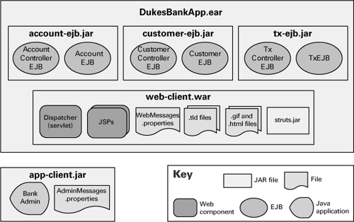
Figure 5.5 The install view of Figure 5.4 rendered in UML. The <<artifact>> stereotype denotes a file of any kind. The <<manifest>> stereotype indicates that a given component, class, or other artifact is inside a given artifact.

5.3.5 Relation to Other Styles
The install style is most strongly related to the C&C styles that describe the software elements for the allocation. The deployment style is also closely related because it shows the hardware elements where the files in an install view are deployed to.
5.4 Work Assignment Style
5.4.1 Overview
The work assignment style allocates modules of a module style to the groups and individuals who are responsible for the realization of a system. This style defines the responsibility for implementing and integrating the modules to the appropriate development teams. The style is typically used to link activities to resources to ensure that the modules are each assigned to an individual or team. The architecture in combination with process determines the actual allocations.
A common managerial tool is the work breakdown structure (WBS). This tool defines a project and groups the project’s discrete work elements in a way that helps organize and define the total work scope of the project. Software WBSs have always been based on some decomposition of the system being built into parts: the modules of a module style.
Because work assignments represent a mapping of the software architecture onto groups of humans, it is an important allocation style. Teams—and hence work assignments—are not simply associated with writing code that will run in the final system. There are many more tasks that humans must perform: configuration management, testing, evaluation of potential commercial off-the-shelf products, ongoing product sustainment, and so on.
Even if a module is purchased in its entirety as a commercial product without the need for any implementation work, someone still has to be responsible for procuring it, testing it, and understanding how it works, and someone has to “speak” for it during integration and system testing. The team responsible for that has a place in a work assignment view, just as do teams responsible for implementing “homegrown” modules.
Moreover, software written to support the building of the system—tools, environments, test harnesses, and so on—and the responsible team have a first-class place in a work assignment view.
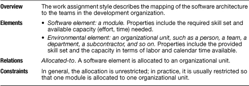
5.4.2 Elements, Relations, and Properties
The elements of this style are software modules and the groups of people in the development organization.
In this style, the allocated-to relation maps from software elements to organizational units.
A well-formed work assignment relation has the property of completeness—all work is accounted for—and no overlap—no work is assigned to two places. Properties of the software elements may include a description of the required skill set, whereas properties of the people elements may include provided skill sets.
Table 5.4 summarizes the characteristics of the work assignment style.
Table 5.4 Summary of the work assignment style
5.4.3 What a Work Assignment Style Is For
The work assignment style shows the major units of software that must be present to form a working system and who will produce them, as well as the tools and environments in which the software is developed (and their assignments to environmental elements). The work assignment style helps with planning and managing team resource allocations, assigning responsibilities for builds, and explaining the structure of a project—to a new hire, for example. The work assignment style can give each team its charter.
This style is the basis for work breakdown structures and for budget and schedule estimates.
5.4.4 Notations for the Work Assignment Style
No special notations exist for showing work assignment views. Among informal notations, a table showing software elements and responsible teams is often sufficient.
Tabular notes are a very simple and clear form of description for work assignment views. The architect doesn’t need to choose the team but rather provide information to management. Later, the actual team assignments can be added.
Figure 5.6 Work assignment view using a tabular notation. The left two columns echo the system’s module decomposition structure.
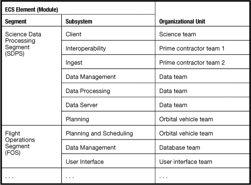
Figure 5.6 shows the primary presentation for a work assignment view of a NASA system called ECS. In the decomposition view for ECS, the highest level modules are called segments; those are decomposed into units called subsystems.
5.4.5 Relation to Other Styles
The work assignment style is strongly related to the decomposition style, because that is the most common basis for its allocation mapping. A work assignment view may extend the module decomposition by adding modules that correspond to development tools, test tools, configuration management systems, and so forth, whose procurement and day-to-day operation must also be allocated to an individual or a team.
![]()
The decomposition style is discussed in Section 2.1.
![]()
Combining views is discussed in Section 6.6.
A work assignment view is often combined with other views. For example, team work assignments could be the modules in a decomposition view, the layers in a layered view, the software associated with tiers in an n-tier architecture, or the software associated with tasks or processes in a multi-process system. You could augment those views by annotating the various software elements with the name of the team assigned to each. Or you could document the assignments as an additional property of the software elements.
The creation of a work assignment view—whether maintained separately or combined with another—enables the architect and the project manager to give careful thought to the best way to divide the work into manageable chunks. This approach also helps keep explicit the need to assign responsibility for all software, such as the development environment that will not be part of the deployed system. A danger of combining work assignments with other views is that the work assignments associated with tool building may be lost; in many situations, the ancillary software tools are not part of the actual system and do not appear in any of other views.
5.5 Other Allocation Styles
So far in this chapter you’ve seen that hardware, file management systems, and team structure all interact with the software architecture. We’ve shown a style that captures each of these allocations from software to external-to-software structures.
There are many other useful mappings of this variety. Here are a few for you to consider:
• Implementation style. The implementation style describes how the development environment is organized in a tree structure of files and folders and how modules from a module view map to that structure. When you apply the implementation style to a system, the resulting implementation view shows how files and folders should be arranged to host the implementation units: classes, programs, scripts, test cases, make files, documentation files, and any other artifacts created when the system is developed. The implementation view helps developers to navigate and locate development artifacts, and to place new artifacts in the proper place. The implementation view also helps in the implementation of version control and configuration management policies. The implementation style is similar to the install style, but instead of showing files and folders in the production environment, it shows the organization of files and folders in the development environment. A screenshot of your development environment tool (which manages the implementation environment) often makes a very useful and sufficient diagram for your implementation view.
![]()
If your development organization will create multiple software systems and wants all of them to follow the same structure for the files and folders in the development environment, you should document an implementation view that serves as a reference for all these software projects.
• Data stores style. The data stores style describes the mapping between the software’s data entities and the hardware of the data servers on which the software resides. When you apply the data stores style to a system, the resulting data stores view shows how the tables containing data described in the data model style are distributed over servers. It might show to which servers stored procedures have been allocated. It might show geographic distribution of the database or database replication. It might also show the machines that host data warehouses and the data stores that feed them. These and other similar relations are important for addressing concerns about data availability, resilience of data to physical attack or cyberattack, as well as how data accesses affect overall system performance. The data stores style is similar to a deployment style, except that (instead of C&C components) it shows data entities allocated to hardware.
![]()
Section 2.6 discusses the data model style.
Other allocation styles are possible. You could define a requirements-allocation style that maps between system requirements and the software elements of the architecture that satisfy them; that’s one way to document a mapping between requirements and design. And for projects spread across many teams and sites, a coordination view can be an important tool to bring the architecture and the development organization into alignment.
![]()
Section 10.3 discusses ways to capture mappings from requirements to software.
See “Perspectives: Coordination Views” on page 209, in this chapter.
There are also useful specializations of the styles discussed in this chapter. For example:
• Specializing the deployment style. The deployment style as presented comes with no inherent topological restrictions, but you might find certain patterns of deployment to be particularly useful. Microsoft publishes a “Tiered Distribution” pattern, which prescribes a particular allocation of components in a multi-tier architecture to the hardware they will run on. This pattern specializes the generic deployment style. If you adopt and document this pattern for your system, the result will be a Tiered Distribution view. Similarly, IBM’s WebSphere handbooks describe a number of what they call “topologies” along with the quality attribute criteria for choosing among them. There are 11 topologies (specialized deployment views) described for WebSphere version 6, including the “single machine topology (standalone server),” “reverse proxy topology,” “vertical scaling topology,” “horizontal scaling topology,” and “horizontal scaling with IP sprayer topology.”
![]()
A style is a specialization of another style if it is consistent with that style—that is, doesn’t violate it—and adds more constraints to its element types, relation types, and/or topological restrictions.
![]()
See the MSDN Web site, msdn.microsoft.com/en-us/library/ms978694.aspx.
![]()
See the IBM Redbooks Web site, www.redbooks.ibm.com/abstracts/sg246446.html.
• Specializing the work assignment style. You can also document often-used team structure patterns as specializations of the work assignment style. In Urdangarin et al. 2008, the authors describe a number of team-organization approaches for globally distributed Agile projects. Each constitutes a specialized work assignment style:
– Platform style. In a software product line development, one site is tasked with developing reusable core assets of the product line, and other sites develop applications that use the core assets.
– Competence-center style. Work is allocated to sites depending on the technical or domain expertise located at a site. For example, user-interface design is done at a site where usability engineering experts are located.
– Open-source style. Many independent contributors develop the software product in accordance with a technical integration strategy. Centralized control is minimal, except when an independent contributor integrates his code into the product line.
They also identify two other organizational allocation schemes that technically do not qualify as specializations of the work assignment style, because they allocate something other than modules to organizational units:
– Process-steps style. Work is allocated across the sites in accordance with the phases of the software development process; for example, design may be done at one site, development at another site, and testing at yet another site.
– Release-based style. The first product release is developed at one site, the second at another site, and so on. Often the releases will be overlapped to meet time-to-market goals; for example, one site is testing the next release, another site is developing a later release, and yet another site is defining or designing an even later release.
Perspectives: Coordination Views
With Jim Herbsleb
A coordination view can be an important tool to bring the architecture and the development organization into alignment, particularly for projects spread across many teams and sites.
The motivation for a coordination view stems from the limitations of communication as a coordination mechanism. Conway (1968) observed decades ago: “Any organization that designs a system will inevitably produce a design whose structure is a copy of the organization’s communication structure.” Small teams can coordinate their work rather simply through frequent communication. But since the number of potential communication paths increases as the square of the number of team members, this strategy does not scale. The usual solution is to divide a system into parts that have limited, well-specified interactions, so that developers working on one part do not need to coordinate their work with developers working on other parts. In the software domain, Parnas (1972) observed long ago that in thinking about criteria for partitioning code into modules, they should be thought of not as subprograms but as “work items” that can be assigned to teams.
Modularization is an essential strategy for allowing development projects to coordinate their work, but it is generally not sufficient. Modules are not completely independent—after all, they form a single system and must therefore interact in some way—and for this reason, the need for teams to coordinate is rarely eliminated completely. In some cases, only minimal coordination will be required, but in other cases, intensive coordination is necessary. The full picture is more complicated, as coordination can happen through shared representations, by prearranged plans and interfaces, and even by a shared work history that enables teams to predict the actions of other teams.
Just as the need to coordinate development work can vary dramatically across modules, the capacity to coordinate can vary dramatically across teams in a project. The key to successful project coordination is to ensure that the coordination required among teams never exceeds the capacity of those teams to coordinate (Cataldo et al. 2006). A coordination view is a tool that can be used to help ensure this condition is not violated.
The key to a coordination view is representing complexity and uncertainty in the relations between modules. Complexity implies that a module and its interfaces are likely to be difficult to understand and to use correctly. Uncertainty means that potentially complicated communication and negotiation between teams and with architects must occur as interfaces are worked out or the allocation of functionality to modules is determined. Representing complexity and uncertainty separately is important, since the means for addressing them are generally quite different. Complexity is generally addressed by detailed documentation, a tactic that is much less useful for handling uncertainty. Frequent Agile-style communication is often an effective way to address uncertainty, but it is easily overwhelmed and ineffective at high levels of complexity. It is important for a useful coordination view to represent both.
One straightforward form a coordination view can take is derived from matrices that represent the relations among modules and the coordination capacities of the project teams. Module relations are represented by two square matrices (like dependency structure matrices), of dimension in the number of modules, with each entry taken from the domain <0, 1, 2, 3>, representing an uncertainty (UM) or complexity (CM) relation between two modules. Zero values indicate modules are not related in any substantial way, while 1, 2, and 3 represent, respectively, low, moderate, and high levels of complexity or uncertainty in the interaction of the modules. Values can be assigned in a variety of ways, for example by an expert such as the lead architect.
![]()
Dependency structure matrices are discussed in Section 1.4.3.
These matrices can be used in conjunction with square matrices representing the relevant coordination capacity of pairs of development teams. The communication capacity matrix (CCM) represents the ease and facility with which two teams can be expected to communicate. This expectation depends on such factors as facility in a common language, cultural similarity, degree of overlap in work hours, use of similar communication technologies, and past experience successfully communicating with each other or similar teams. The documentation capacity matrix (DCM) represents the ease and facility with which two teams can be expected to create relevant documentation and achieve a common understanding of it. This expectation depends on such factors as experience with relevant notations (for example, are both teams experienced in UML if that is the chosen format), history of creating and maintaining detailed and accurate documentation of APIs, and the demonstrated willingness to publish and read documentation. For both matrices, the values can again be taken from the domain <0, 1, 2, 3>, representing approximate levels of communication or documentation capacity of pairs of teams.
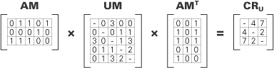
We now have four square matrices: two of dimension number of modules (UM, CM), and two of dimension number of teams (CCM, DCM). In order to compare coordination needs with coordination capacities, it is necessary to express both as relations among teams. Some additional computation with UM and CM will achieve this. All that is required is to use an allocation view in the form of a binary matrix AM of teams by modules, where an entry of 1 indicates that a team is responsible for a given module. The following multiplication represents the degree to which each pair of teams can expect to be required to coordinate uncertainties (where AMT is the transpose of AM).
AM × UM × AMT = CRU
The product CRU is a square matrix of dimension in the number of teams, where entries give an indication of the extent to which each pair of teams is working on modules that interact with uncertain interfaces and/or uncertain allocation of functionality. This indication is very approximate, but a comparison of values in CRU and CCM should give useful indication where much communication is going to be required (relatively large entries in CRU) and little communication capacity exists (relatively small entries in comparable cells of CCM). Such mismatches should trigger discussions about how communication can be supported or how work can be reassigned in order to sidestep communication problems. An analogous computation substituting CM for AM and DCM for CCM will provide a comparison of the need of teams to coordinate through documentation and their capacity to do so.
Let’s illustrate with a small example. Let AM, a matrix of dimension teams by modules, represent assignment of code modules to teams for development. This is simply a work assignment view. UM is an uncertainty matrix, representing the lead architect’s judgment about the relative degree of uncertainty, for each pair of modules, of the interface and the allocation of functionality between the modules. CRU represents the extent to which each pair of teams can expect to be required to coordinate uncertainties.
![]()
Work assignment views are discussed in Section 5.4.
CRU can now be compared with communication capacities of the teams, CCM, or used to plan how the work is assigned. It is a good bet, for example, because of the work they are performing, teams 1 and 3 will require a very robust communication capacity, if not collocation. This because of the considerable uncertainty between modules 1 and 3 as well as 3 and 5. Teams 2 and 3 will have relatively little need to work out uncertainties, meaning they can probably be located anywhere and will need no special communication technologies. Teams 1 and 2 will have a moderate need to communicate, suggesting they should work in time zones that allow overlapping work hours and have adequate teleconferencing and perhaps instant-messaging technologies. Their coordination success should be carefully monitored to ensure they don’t get out of sync.
Additional experience with coordination views will eventually tell us when this simple construction is sufficient, and when more nuanced schemes, perhaps attuned to architecture styles or other key attributes, will add value. We may also need more systematic ways of assigning values to both need and capacity. Such issues are the subject of ongoing research (Urdangarin et al. 2008; Avritzer, Cai, and Paulish 2008).
5.6 Summary Checklist
• Allocation styles map software elements to elements in the environment of the software.
• A deployment view describes the mapping of runtime software elements to the hardware of the computing platform on which the software executes.
• An install view describes the tree structure of files and folders in the production environment and how the software components are mapped to that structure.
• A work assignment view describes the mapping of modules onto the people, groups, or teams tasked with the development of those modules.
5.7 Discussion Questions
1. Consider a network diagram created by the network administrator in the IT department of your organization. How does that diagram compare with a deployment view? What is missing?
2. Suppose that you needed to map the modules under test to the test harness that generates inputs, exercises the modules, and records the outputs. Sketch an allocation style that addresses this concern.
3. In one project, short identifiers were assigned to every module. A module’s full name consisted of its identifier, prefixed by its parent’s identifier, separated by a period (.). The project’s file structure was defined by a short memorandum stating the path name of a root directory and further stating that each module would be stored in the directory obtained by changing each period in the module’s full name to a slash (/). Did this memorandum constitute an implementation view for this system? Why or why not? What are the advantages and disadvantages of this scheme?
4. Suppose that your system can be deployed on a wide variety of computing platforms and configurations. How would you represent that?
5. Besides the ones in this chapter, identify as many other structures in the environment of a software system as you can. Pick a few and answer the following: What software elements would map to it? Create an example primary presentation for a corresponding view. Discuss to whom such a view would be useful and what concerns it would address.
6. Many deployment tools and integrated development environments provide views of the development and production environments that allow you to easily understand and navigate the tree structure of files and folders. Do you think these tools can fill the need for creating install views or implementation views in the architecture documentation? Why so, or why not?
5.8 For Further Reading
Both the install style and the implementation style are aligned with the broad topic of software configuration management (SCM). An in-depth treatment of SCM is far beyond the scope of this book, but you can begin investigating the topic by looking at the documentation of SCM and version-control tools, such as Subversion, CVS, Perforce, ClearCase, and Visual SourceSafe. The Siemens Four View model defines a code architecture view that explains how the software implementing the system is organized into source, intermediate, and deployment components and related decisions regarding build and installation procedures and configuration management (Hofmeister, Nord, and Soni 2000).
In the 1960s Conway (1968) formulated a law that the architectural structure mirrors the organizational structure. He based his law on ease of communication within as opposed to across groups. This law is an organizational articulation of coupling and coherence. Architecture-based management of software projects is also discussed in the book by Paulish (2002). He has observed that accurate time and budget estimates depend on basing them on the software architecture. This is the place where a work assignment view comes into play; Paulish’s observation has a strong intuitive base, as the time and budget estimates depend on the work breakdown structure, which in turn depends on the software architecture. More recently, Avritzer and others have observed many different organizational approaches to assign work in globally distributed teams (for example, product structure, process steps, release-based, computing platform structure, competence center, and open source) (Avritzer, Cai, and Paulish 2008). Avritzer explicitly discussed assigning work in globally distributed teams.