10. Building the Documentation Package

You now have everything you need to begin building the complete documentation package. You have a repertoire of styles from which you can construct views, a method for choosing the most useful views to document, and insights about how to document architecture information beyond structure: context, diagrams, variability, interfaces, and behavior. This chapter shows you how to put it all together.
First, we return once again to our fundamental principle of documenting architectures:
Documenting an architecture is a matter of documenting the relevant views and then adding documentation that applies to more than one view.
Rule 4 for sound documentation, given in the prologue, counsels us to use a standard organization for documents. Combining these two foundations, this chapter provides standard document organizations for documenting architecture views, along with the information that transcends views.
10.1 Documenting a View
Figure 10.1 shows the template for documenting a view.

10.1.1 A Standard Organization for Documenting a View
No matter what the view, the documentation for a view can be placed into a standard organization consisting of these parts.
Section 1. The Primary Presentation
The primary presentation shows the elements and relations of the view. The primary presentation should contain the information you wish to convey about the system—in the vocabulary of that view—first. It should certainly include the primary elements and relations but under some circumstances might not include all of them. For example, you may wish to show the elements and relations that come into play during normal operation but relegate error handling or exception processing to the supporting documentation. What information you include in the primary presentation may also depend on what notation you use and how conveniently it conveys various kinds of information. A richer notation will tend to enable richer primary presentations.
![]()
Drawings help people to work out intricate relationships between parts.
—Christopher Alexander
The primary presentation is most often graphical. It might be a diagram you’ve drawn in an informal notation using a simple drawing tool, or it might be a diagram in a semiformal or formal notation imported from a design or modeling tool that you’re using. The figures that illustrate diagrams from example views in Chapters 2, 4, and 5 are all diagrams that would appear in a primary presentation.
![]()
If your primary presentation is graphical, make sure to include a key that explains the notation.
Sometimes the primary presentation can be textual, such as a table or a list. If that text is presented according to certain stylistic rules, they should be stated or incorporated by reference, as the analog to the graphical notation key. Regardless of whether the primary presentation is textual instead of graphical, its role is to present a terse summary of the most important information in the view.
![]()
An example of a textual primary presentation is shown in Figure 2.4, in Section 2.1.6.
The primary presentation may feature more than one diagram. For example, suppose the system has two separate subsystems, each of which is built using the pipe-and-filter style. A pipe-and-filter view of this system could have two diagrams in its primary presentation. Each would show the pipe-and-filter elements in one of the two subsystems.
To remind us that the primary presentation is only the starting point for documenting a view, we call the graphical portion of the view an architecture cartoon. We use the definition from the world of fine art: A cartoon is a preliminary sketch of the final work; it is meant to remind us that the picture, although getting most of the attention, is not the complete description but only a sketch of it.
![]()
An architecture cartoon is the graphical portion of a view’s primary presentation, without supporting documentation.
![]()
If the view derives from one or more published styles or patterns, let the reader know. It is most convenient to do this by adding an annotation to the primary presentation or (if it’s graphical) adding a note in the notation key. Be sure to cite the published source and not just name the pattern or style, since many patterns and styles with common names are described differently by different authors.
See “Not Every View Comes from a Published Style or Pattern,” on page 343.
Section 2. The Element Catalog
The element catalog details at least those elements depicted in the primary presentation. For instance, if a diagram shows elements A, B, and C, then the element catalog needs to explain what A, B, and C are and their purposes or the roles they play, rendered in the vocabulary of the view. In addition, if elements or relations relevant to this view were omitted from the primary presentation, they should be introduced and explained in the catalog. Specific parts of the catalog include the following:
a. Elements and their properties. This section names each element in the view and lists the properties of that element. Each style introduced throughout Part I listed a set of suggested properties associated with that style. For example, elements in a decomposition view might have the property of “responsibility”—an explanation of each module’s role in the system—and elements in a communicating-processes view might have timing parameters, among other things, as properties. Whether the properties are generic to the style chosen or the architect has introduced new ones, this is where they are documented and given values.
![]()
Section I.3, in the introduction to Part I, discusses how to choose properties to document.
b. Relations and their properties. Each view has specific relation type(s) that it depicts among the elements in that view. Mostly, these relations are shown in the primary presentation. However, if the primary presentation does not show all the relations, or if there are exceptions to what is depicted in the primary presentation, this is the place to record that information. Otherwise, this section will be empty.
![]()
Documenting interfaces is covered in Chapter 7.
Documenting behavior is covered in Chapter 8.
Context diagrams are discussed in Section 6.3.
Using a variability guide to document architecture variation points is covered in Section 6.4.4.
Documenting rationale is covered in Section 6.5.
c. Element interfaces. This section documents element interfaces.
d. Element behavior. Some elements have complex interactions with their environment. For purposes of understanding or analysis, it is incumbent on the architect to specify element behavior.
Section 3. Context Diagram
A context diagram shows how the system or portion of the system depicted in this view relates to its environment.
Section 4. Variability Guide
A variability guide shows how to exercise any variation points that are a part of the architecture shown in this view.
Section 5. Rationale
Rationale explains why the design reflected in the view came to be. The goal of this section is to explain why the design is as it is and to provide a convincing argument that it is sound. The use of a pattern or style in this view should be justified here.
Items 2–5 are called the supporting documentation and explain and elaborate the information in the primary presentation.
10.1.2 Useful Variations in the Standard Organization for a View
The standard organization for documenting a view presented in the last section serves well in most cases. However, there are some useful variations that may serve better in others. These include the following:
Variation 1: Divide the View into View Packets
Views of large software systems can contain hundreds or even thousands of elements with arbitrarily deep levels of nesting. Showing these elements in a single presentation, along with the relations among them, can result in a blizzard of information that is indecipherable. Also, many stakeholders aren’t interested in the entire view, just their little part of it. Or just the broad picture bereft of much detail. In some organizations, you might want to impose access control on parts of a view you don’t want your subcontractors to look at.
![]()
A view packet is the smallest bundle of view documentation you would show an individual stakeholder, such as a developer assigned to implement a small portion of the system or a customer interested in an overview.
If you need a way to present a view’s information in smaller “chunks,” break it up into view packets. Each view packet can show a fragment of the system with great depth of detail, or broad areas of the system with shallower detail. The documentation for a view, then, can consist of a set of view packets.
View packets make an excellent way to help the architect carry out and record refinements as they are made as part of the journey through the spectrum of design.
![]()
Refinement and the spectrum of design are discussed in Chapter 6. For an example of using view packets to record more and more detailed architectural decisions, see the sidebar “Using View Packets to Record Architecture Design Steps,” on the next page.
The same standard organization we used for a view also works for a view packet. Just remember:
• The primary presentation shows the elements and relations that populate the portion of the view shown in this view packet, rather than the whole view.
• The supporting documentation (element catalog, context diagram, variability guide, and rationale) all explain just the part of the architecture shown in the primary presentation. The “environment” shown in the context diagram may well be other elements that are internal to the overall system whose architecture we’re documenting.
• As an aid to readers’ navigation among view packets, it helps to add a pointer to a view packet’s parent view packet as well as its sibling and child view packets. (A “child” view packet is one that shows a decomposition refinement of one or more elements in its “parent” view packet.)
![]()
Decomposition refinement is discussed in Section 6.1.1.
If you divide a view into view packets, preface the set with an explanation of what view packets are provided and what part of the system each one shows. One way to do this is to show the context diagram for each included view packet, with parent/child links among the diagrams, to help a reader navigate to and identify the view packet he or she wants to see.
Advice: Using View Packets to Record Architecture Design Steps
Throughout this book, we have tried to make the point that architecture documentation is not just a necessary afterthought of architecture design, but an important contributor to the design process itself. View packets make an excellent vehicle for storing architecture decisions as they are made, making architecture design and documentation go hand in hand.
We illustrate this concept using version 2 of the Attribute-Driven Design (ADD) method. ADD is a step-by-step architecture design method that relies on iteratively choosing a part of the system to design, and then choosing appropriate architecture styles, patterns, and tactics to satisfy the architecturally significant requirements for that part. The result of each ADD iteration can be recorded in its own view packet.
Since ADD is a sequential, step-by-step method, you can also record the chronology of your design—what decisions came before and after what other decisions. This will be helpful if you need to change a design decision. You can easily see what design decisions you made after the one in question, to determine if they need to change as well.
Below are the rough steps of ADD, along with what you should record in a view packet when you carry out each one.
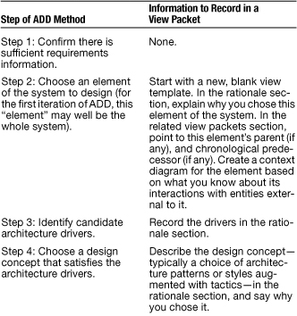
![]()
Don’t try to record all the information in pristine, ready-for-primetime fashion. For one thing, ADD includes a back-up-and-try-again option in step 4. (Perhaps the design concept you chose three iterations ago unwittingly precluded meeting the requirements you’re handling in the current iteration. You’ll have to back up and try again.) So don’t waste time making the information beautiful. Instead, make it comprehensible. You can shine it up when you have an architecture you have confidence in.
Notice how using view packets to hold design decisions as you go obviates the question of what views to use during architecture design. Your choice of architecture patterns and styles binds you to a choice of views. If you choose a service-oriented style when designing a system (or portion of a system), you’ll document a service-oriented view to capture its instantiation; if you choose a layered style, you’ll document a layered view to capture its instantiation; and so forth. Later, when you have a collection of view packets representing a collection of views, you can assemble them into collections that make sense using the Choosing the Views approach of Chapter 9.
Variation 2: Add a Section to Document the Behavior of the Whole Architecture Shown in the Primary Presentation of a C&C View
The primary presentation of a C&C view shows a group of architecture elements (components and connectors) and their runtime interactions. The element catalog contains the behavior of those elements. But you’ll almost certainly want to document the behavior of the group as a whole somewhere. Where? Alternatives include the following:
• The behavior section of the view’s element catalog. This section is primarily intended to capture the behavior of individual elements. You could add a special entry at the end to capture the behavior of everything working together.
• A new section in the standard organization for a view. Architects often show structure and the behavior of that structure next to each other, affording equal status to both. Giving the behavior its own section makes that easier.
• If you use view packets, you don’t need to change the template. The group of components and connectors shown in a view packet might well be a specialization of a single component or connector shown in a parent view packet. In that case, its behavior will be documented in the element catalog of the parent view packet.
![]()
If you combine the primary presentation with context, make sure to indicate the system boundary. Either use a clear distinguished bounding symbol, and put that symbol in your key, or indicate clearly which elements are external to the system.
Variation 3: Combine the Primary Presentation and Context Diagram
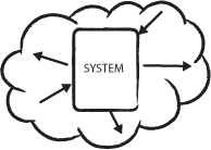
Stripped to its essentials, a context diagram shows the system being described along with external elements with which it interacts or is related. As shown in Figure 10.2, the system is depicted as a monolithic entity, starkly bounded, with no internal structure: a black box.
Figure 10.2 A pure context diagram shows the system, with no internal structure shown, and its relations to entities in its environment.
Showing the internal structure is the job of the primary presentation. While this represents a useful separation of concerns in many cases, sometimes the primary presentation can be more expressive if it contains external entities. Especially with C&C views, combining the primary presentation with the context diagram lets you see where the arrows begin and end, which can help you ensure that none of the ties between system internals and externals is overlooked.
It’s common to see external entities in primary presentations, but architects usually don’t bother indicating the fact that some of the elements they’re showing are external. This can be confusing. Figure 10.3 is an example of a cartoon that combines a primary presentation with a context diagram.
Figure 10.3 A context diagram and a primary presentation combined. Here, the external entities are denoted by symbols identified in the key.
Variation 4: A View with a Multi-part Primary Presentation
Recall that the point of view packets was to keep from having to present a massive (and massively complex) single diagram of interest to almost no one. If for some reason your stakeholders are not well served by dividing the view into view packets, you can document the whole view using a series of diagrams in its primary presentation—the diagrams that would have populated the view packets. The supporting documentation in sections 2–5, then, will explain those diagrams taken as a whole. If you take this option, you’ll have to explain how the diagrams relate to each other and/or how to navigate among them.
10.1.3 Avoiding Unnecessary Repetition Across Views or View Packets
Using the view or view packet template naively might result in information being repeated in more than one place, violating our injunction in Section P.5 to avoid unnecessary repetition. Cases include the following:
A module or a component appears in more than one view. For example, the same module might appear in a decomposition, uses, and generalization view. Rather than give its definition, properties, interface, and behavior in the element catalog of every view in which it appears, you can do the following:
• Pick the view in which it seems most appropriate to capture this information, and have the element catalogs in the other views simply refer to it.
• Package the potentially redundant information separately and have all views refer to it or automatically incorporate it.
• In the case of online documentation, have every view’s element catalog link to the information.
The context diagram of a child view packet looks like the primary presentation of its parent. Suppose a view packet shows an element without internal substructure, but you create another view packet to show the decomposition refinement of that element—that is, to reveal its internal substructure. Then the context diagram for the second view packet is going to look a lot like the primary presentation for the first. In that case, make the context diagram a simple pointer to the first view packet’s primary presentation.
![]()
Decomposition refinement is covered in Section 6.1.1.
Global policies apply to many elements. Architects often make decisions that apply to all the elements in a view, such as “All components must write a human-readable message to a log after the start and finish of every transaction.” To document information like this, you can do any of the following:
• Add an annotation to the view showing the affected elements.
• Add an entry at the beginning of the element catalog.
• Add an entry to the behavior documentation.
• Explain the global policy in the architecture background section of the documentation beyond views (see Section 10.2).
![]()
Rozanski and Woods call information like this part of the “common design model.” See Section E.3.
If you use view packets, you can document global policies in either of two places:
• In the same place that lists the view packets in a view, you can also put information common across all view packets, as a way of “factoring out” commonality and putting it in one place to avoid repetition.
• In a view packet with the greatest scope and least depth. Then all other view packets can “inherit” the common information.
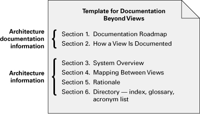
10.2 Documentation Beyond Views
In many ways, an architecture is to a system what a map of the world is to the world. Thus far, we have focused on capturing the various architecture views of a system, which tell the main story. In the words of Miles Harvey, they are the “continents, oceans, mountains, lakes, rivers, and political borders” of the map that we are drawing. But we now turn to the complement of view documentation, which is capturing the information that applies to more than one view or to the documentation package as a whole. Documentation beyond views corresponds to the adornments of the map, which complete the story and without which the work is inadequate.
10.2.1 A Standard Organization for Documenting Information Beyond Views
Documentation beyond views can be divided into two parts:
1. Information about the architecture documentation. How the documentation is laid out and organized so that a stakeholder of the architecture can find the information he or she needs efficiently and reliably.
2. Information about the architecture. Here, the information that remains to be captured beyond the views themselves is a short system overview to ground any reader as to the purpose of the system, the way the views are related to one another, an overview of and rationale behind system-wide design approaches, a list of elements and where they appear, and a glossary and an acronym list for the entire architecture.
Figure 10.4 summarizes documentation beyond views.
Figure 10.4 Summary of documentation beyond views
Document Control Information
List the issuing organization, the current version number, the date of issue and status, a change history, and the procedure for submitting change requests to the document. Usually this is captured in the front matter. Change-control tools can provide much of this information.
Section 1. Documentation Roadmap
The documentation roadmap tells the reader what information is in the documentation and where to find it.
![]()
“Would you tell me, please, which way I ought to go from here?”
“That depends a good deal on where you want to get to,” said the Cat.
“I don’t much care where,” said Alice.
“Then it doesn’t matter which way you go,” said the Cat.
—Lewis Carroll, Alice in Wonderland
A roadmap consists of four sections:
1. Scope and summary. Explain the purpose of the document and briefly summarize what is covered and (if you think it would help) what is not covered. Explain the relation to other documents (such as downstream design documents, or upstream system engineering documents).
2. How the documentation is organized. For each section in the documentation, give a short synopsis of the information that can be found there. An alternative to this is to use an annotated table of contents. This is a table that doesn’t just list section titles and page numbers, but also gives a synopsis with each entry. It provides one-stop shopping for a reader attempting to look up a particular kind of information.
3. View overview. The major part of the roadmap describes the views that the architect has included in the package. For each view, the roadmap gives
i. The name of the view and what style it instantiates.
ii. A description of the view’s element types, relation types, and property types. This lets a reader begin to understand the kind of information that is presented in the view.
iii. A description of language, modeling techniques, or analytical methods used in constructing the view.
4. How stakeholders can use the documentation. The roadmap follows with a section describing which stakeholders and concerns are addressed by each view; this is conveniently captured as a table. This section shows how various stakeholders might use the documentation to help address their concerns. Include short scenarios, such as “A maintainer wishes to know the units of software that are likely to be changed by a proposed modification. The maintainer consults the decomposition view to understand the responsibilities of each module in order to identify the modules likely to change. The maintainer then consults the uses view to see what modules use the affected modules (and thus might also have to change).”
![]()
To be compliant with ISO/IEC 42010:2007 (see Section E.1), you must consider the concerns of at least users, acquirers, developers, and maintainers.
Section 2. How a View Is Documented
Adopting a standard organization means using it, but also explaining it. This is where you explain the standard organization you’re using to document views—either the one described in this chapter or one of your own. It tells your readers how to find information in a view.
If your organization has standardized on a template for a view, as it should, then you can simply refer to that standard. If you are lacking such a template, then text such as that in Section 10.1.2 should appear in this section of your architecture documentation.
Section 3. System Overview
This is a short prose description of the system’s function, its users, and any important background or constraints. The purpose is to provide readers with a consistent mental model of the system and its purpose.
The system overview is, strictly speaking, not part of the architecture—that is, it is not part of the designed solution.
However, it is indispensable for understanding the architecture. If an adequate system overview exists elsewhere, such as in the overall project documentation, you can incorporate it by reference.
Section 4. Mapping Between Views
Because all the views of an architecture describe the same system, it stands to reason that any two views will have much in common. Helping a reader understand the associations between views will help that reader gain a powerful insight into how the architecture works as a unified conceptual whole. Being clear about the association by providing mappings between views is key to increasing understanding.
The associations between elements across views in a particular architecture are in general many-to-many. For instance, each module may map to multiple runtime elements, and each runtime element may map to multiple modules. Sometimes runtime elements of the system do not exist as code elements at all, such as when they are imported at runtime or incorporated at build or load time. Sometimes modules, such as layers, do not appear at runtime. In general, parts of elements in one view correspond to parts of elements in another view.
There are three ways to document a mapping between views.
1. State a rule that lets a reader know how to look at two views and see the association between elements in each. Naming conventions often provide convenient rules for mappings. The simplest rule is that if an element with the same name appears in different module views, or two different C&C views, it’s the same element.
2. View-to-view associations can be conveniently captured as tables, such as the one in Figure 10.5, taken from the Duke’s Bank example. List the elements of the first view in some convenient lookup order. The table itself should be annotated or introduced with an explanation of the association that it depicts; that is, what the correspondence is between the elements across the two views. Examples include “is implemented by,” for mapping from a component-and-connector view to a module view; “implements,” for mapping from a module view to a component-and-connector view; “included in,” for mapping from a decomposition view to a layered view; and many others.
Figure 10.5 An excerpt from a mapping between views
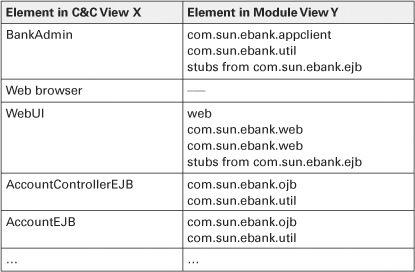
![]()
Duke’s Bank is an example application used in Sun’s online Java tutorial. See java.sun.com/j2ee/tutorial/1_3-fcs/doc/Ebank.html.
3. The mapping can be shown graphically. An example is shown in Figure 10.6.
Figure 10.6 A graphical mapping between views. On the far right are UML packages that correspond to modules from a decomposition view. The <<manifest>> relations show the different JAR files (UML artifacts) inside which the modules are bundled for deployment. The <<deploy>> relations show how the JAR files (MySystem.ear, MySystem.war, and corporative.jar) are deployed to the production platform. The platform elements on the left are represented as UML nodes and come from the deployment view of the architecture.
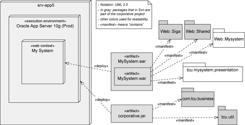
![]()
Allocation views (discussed in Chapter 5) also show mappings. They map between software structures and nonsoftware structures in the system’s environment.
For which views should you provide an explicit mapping? (Mappings using naming conventions are implicit.) Begin with these rules of thumb:
• Provide a mapping between the decomposition view and every C&C view.
• Ensure at least one mapping between a module view and a component-and-connector view.
• If your system uses more than one module view, map them to each other.
![]()
Use the guidelines in Section 6.5 to help you capture the key architecture decisions.
Section 5. Rationale
This section documents the architectural decisions that apply to more than one view. Prime candidates include documentation of background or organizational constraints or major requirements that led to decisions of system-wide import. The decisions about which fundamental architecture patterns or styles to use are often described here.
![]()
We are searching for some kind of harmony between two intangibles: a form which we have not yet designed and a context which we cannot properly describe.
—Christopher Alexander
Section 6. Directory
The directory is a set of reference material that helps readers find more information quickly. It includes the following:
• Index. Include an index of the elements, relations, and properties that appear anywhere in the architecture documentation. The index should also distinguish between pages where a term is used and the page where it is first defined. A convenient way to do this is to embolden the page number on which the term is defined. (An online search capability may obviate this need.)
![]()
Include terms in the glossary that your stakeholders won’t necessarily know, or terms whose meaning might not be the same among stakeholders.
• Glossary. The glossary defines terms used in the architecture documentation that have special meaning. Often there is a system-wide glossary; if that exists and suffices, it can be incorporated by reference.
• Acronym list. Make sure to define the important acronyms you use in the architecture documentation. Again, projects often keep a system-wide acronym list, which can be incorporated by reference.
• Referenced material. This is the place to put references to material cited throughout the architecture documentation.
10.2.2 Useful Variations in the Standard Organization for Documentation Beyond Views
Variation 1: Document How to Use the Architecture
You may wish to document “use cases” for the architecture—that is, how to use the architecture to build applications. This is especially helpful if the architecture is meant to be a product-line architecture. People usually learn by internalizing examples, so give a few. Start small; show how to build your application’s equivalent of “hello, world!” and then work up. Audiovisual media such as a video or a podcast can be useful in demonstrating the use cases.
![]()
See “Coming to Terms: Product-Line Architectures” on page 234, Chapter 6.
![]()
The idea for using audiovisual media to document architecture comes from Markus Voelter, coauthor of the (German) book Software Arkitektur. He was interviewed during the OOPSLA 2007 conference. You can find the interview at infoq.com/interviews/MarkusVoelteraboutSoftwareArchitectureDocumentation.
Variation 2: Document the Major Design Approaches Taken
Architectures often have dominating “motifs” or design approaches, and elegant ones almost always do. These approaches often take the form of well-known architecture styles or patterns, but other overarching motifs are possible as well. For example, your architecture may dictate that elements implementing new functions all have certain programs on their interfaces, or share data or handle errors in a particular way.
Variation 3: Make a Single Element Catalog for the Whole Architecture
Because the same element might appear in more than one view, there is a danger that its element catalog entries will be redundant. An option is to take all of the element catalogs and merge them into a single one for the whole architecture. This “supercatalog” would belong in the “documentation beyond views” part, because it obviously contains information common to more than one view.
Be careful if you take this option. Describing an element in separate views tends to reinforce the specific role the element plays in the architecture in each view, and that’s helpful. For example, a module (in a decomposition view) is usually described in terms of what kinds of changes it encapsulates against, whereas the same module (in a uses view) is described in terms of what it uses and the role it plays in incremental development. The same element, showing up as a component in some C&C view, would be described in terms of its interactions with other elements and its runtime quality attribute properties. Just giving an element a single element catalog entry runs the risk of overlooking what it contributes to each view in which it appears.
Variation 4: Add a Section to Record Open Questions
This is particularly helpful during early development. It provides a “to do” list for the architect, and it informs stakeholders of the major unknowns (and hence possible areas of instability) still in the architecture.
10.3 Documenting a Mapping to Requirements
In many projects, showing how the architecture satisfies requirements is an important part of the documentation. This helps to validate the architecture by showing that
• No requirement was forgotten.
• No requirement was contradicted.
• Every architectural decision is either predicated on at least one requirement or legitimately within the discretion of the architect. (Not every architectural decision satisfies a stated requirement.)
To facilitate validation, the architect records a mapping between architectural decisions and requirements. Anyone interested in a particular requirement should be able quickly to find where in the architecture it is handled.
![]()
A detailed mapping to requirements often changes quite frequently during a project’s life cycle. Consider capturing the mapping in a database rather than a static document, to facilitate updates and to allow queries and searches to be run.
The mapping can be as detailed as the requirements themselves. Projects with formal requirements documents generally have detailed mappings, whereas projects with informal or fluid requirements (especially Agile projects) will have less detailed mappings. Mappings are conveniently recorded in tables such as in Figure 10.7.
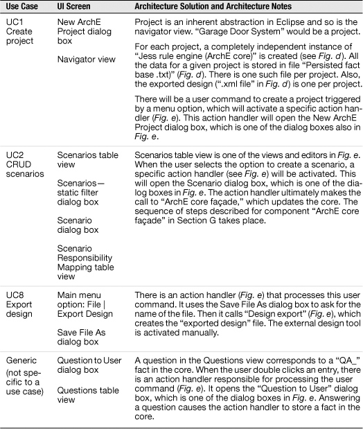
Figure 10.7 This figure shows an excerpt of the mapping between functional requirements (here, use cases) and architecture for the ArchE system. Because ArchE is a GUI desktop application, most of the use cases are mapped to one or more UI screens (second column). The third column describes how each use case is handled in the architecture. The figures mentioned in the description are primary presentations of the view(s) where the referenced element is defined. (Sections 2.3.6 and 6.6.4 have more information about the ArchE tool.)
You can document a mapping to requirements in any of the following ways.
1. Put the mapping in a single place in the documentation, a new section in the documentation beyond views. This option is good for projects that have informal or fluid requirements or that do not require fine-grained accounting of each requirement. Putting the information in one place makes it is easy to update and convenient for validation, and it doesn’t clutter the documentation with information that is needed only for a short while by just a few stakeholders. This option most often takes the form of a table that maps a requirements reference to an architecture element, decision, or section of the architecture document. An example is shown in Figure 10.7.
2. Distribute the mapping throughout the architecture documentation. You could add a separate section to each view. Or you could overlay every place in the architecture with a tag or adornment that reflects a requirement—every primary presentation, element catalog, context diagram, or variability mechanism. This option is good for projects with fine-grained requirements that map to fine-grained architectural decisions. The architect can record the requirements addressed in the same place and at the same time as the architecture decisions are made. It’s also reasonably convenient if the documentation is in an electronic form that allows us to switch the adornments on and off or (even better) automatically extract, collect, and index them to produce an all-in-one-place summary.
3. Capture the mapping to requirements in a view of its own. This option is explored in the sidebar “The Requirements Viewpoint.” Where might such a view belong in the Style Zoo?
– You could consider the requirements a “structure” in the software’s environment as real as the organizational, development, or execution structures. Thus, a mapping to requirements could be considered a new kind of allocation style, and documented as a kind of allocation view.
– You could consider the requirements as a set of concerns that crosscut the architecture elements you’ve designed. Thus, a mapping to requirements could be considered a kind of aspect view. This option is good for projects with fine-grained requirements that map to multiple architectural decisions or elements.
Advice: The Requirements Viewpoint
With Peter Eeles
Beyond the approaches for capturing a mapping to requirements outlined in this chapter, there are several precedents for treating the requirements that influence the architecture as a more first-class citizen in terms of an architecture description. For example, there is Kruchten’s “Plus One View” of architecture, whose scenarios “are in some sense an abstraction of the most important requirements” (Kruchten 1995). In “The Process of Software Architecting” (Eeles and Cripps 2009), the authors take this thinking further by introducing a more comprehensive requirements viewpoint. A requirements view, based on this viewpoint, describes those requirements that have shaped the architecture, and may include functional requirements, quality attribute requirements, and constraints.
![]()
You can read about the 4+1 approach in Section E.2.
![]()
ISO 42010 defines viewpoint as a work product establishing the conventions for the construction, interpretation, and use of architecture views and associated architecture models (ISO/IEC 42010:2007). ISO 42010 is described in Section E.1.
The value of a requirements view, however, is not confined to the identification of the subset of requirements that are deemed to be architecturally significant; the architecture description as a whole should explicitly define how the architecture addresses each of these requirements. Such “traceability” from architecture to requirements can be particularly useful during architecture reviews when the architect needs to justify their decisions, or when the architect needs to remind themselves of the rationale for their decisions.
![]()
One place this traceability might be captured is in the rationale section of your documentation. Documenting rationale is described in Section 6.5.
The architecturally significant requirements that you capture in a requirements view may be defined within the current project that is responsible for developing the system, or they may come from outside the project (such as an enterprise architecture or an industry body defining mandatory regulations). The solution architecture is derived from both sets of requirements, as shown in Figure 10.8, with the outermost ring representing requirements defined outside the project, the inner ring representing those requirements defined within the current project (and that align with the requirements defined outside the project), and the center representing the solution architecture that is shaped by both sets of requirements.
Figure 10.8 Elements of a requirements view (Eeles and Cripps 2009)
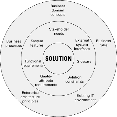
Elements defined within the project may include stakeholder needs, system features, interfaces between the system and external entities, functional requirements, a glossary of terms, quality attribute requirements, and any constraints on the solution. Elements defined outside the project, but that also influence the architecture of the system, may include a definition of the key concepts in the business domain, business processes, business rules, principles that inform and guide the way in which the system will be created (such as “buy versus build”), and a description of existing elements that comprise the current IT environment and that may be used by, or constrain, the system under development. These elements constitute the contents that you should capture and document in a requirements view.
10.4 Packaging the Architecture Documentation
10.4.1 Packaging Schemes
You can use the templates in this chapter to create architecture documentation structured in a variety of ways. Which option you choose will depend on the size of the system, how you wish to package it for its stakeholders, and your organization’s standards and practices.
Produce All One Package
Here is a suggested ordering for producing a single architecture document:
1. Document control information
2. Documentation roadmap
3. How a view is documented
4. System overview
5. Views
6. Mapping between views
7. Rationale
8. Directory
Produce Separate Documents
If a single document seems too unwieldy, there are a number of ways to divide the documentation into more manageable chunks. One way is to break the views out into their own document. If you do that, then it makes sense to put the “How a view is documented” section with them. Both documents should have document control information.
Other arrangements are possible, such as putting every view in its own document, grouping views by category (module, C&C, allocation), or breaking out the mapping to requirements into its own document. You may also wish to divide the documentation along architectural lines—a document per subsystem, for example. Consult your stakeholders to find out what would work best for them.
Produce Documentation Packages from Different Views
A view is a representation of a set of element types and relation types applied to a system. If you break a view into view packets, then every view packet in that view shares the same underlying type. This is not always the most convenient documentation package to give to a stakeholder. Stakeholders are often interested in, for example, shallow overviews of the whole system, or holistic (that is, multi-view) insight and detail about a particular subsystem or layer.
To serve stakeholders like these, you can put together a package of information including view packets from different views. For example, you can assemble a package that provides a broad overview of the architecture by showing high-level view packets from various views. This can be followed by view packets that show deeper and deeper levels of the architecture, again across views. The documentation roadmap for documentation like this must tell the reader how to navigate through the view packets.
10.4.2 Online Documentation, Hypertext, and Wikis
These days, Web-based documentation is becoming the norm. Hyperlinking your documents can provide easy navigation in and among them, as well as instant access to related documents, definitions, catalogs, and external references. Hyperlinking also relieves you of all the problems associated with keeping multiple copies of documents around: You make one copy and link to it wherever the information contained in it is needed. (Recall the second rule of sound documentation: Avoid unnecessary repetition.)
Prepared using a Web-based documentation tool, a document can be structured as linked Web pages. Compared with documents written with a text-editing tool, Web-oriented documents typically consist of short pages (created to fit on one screen) with a deeper structure. One page usually provides some overview information and has links to more-detailed information. When done well, a Web-based document is easier to use for people who just need to have some overview information. On the other hand, it can become more difficult for people who need detail. Finding information can be more difficult in multi-page, Web-based documents than in a single-file, text-based document, unless a search engine is available.
![]()
Shared documentation, in a Web-based environment, allows you to increase collaboration among stakeholders and avoid unnecessary repetition.
Using readily available tools, it’s possible to create a shared document that many stakeholders can contribute to. The hosting organization needs to decide what permissions it wants to give to various stakeholders; the tool used has to support the permissions policy. In the case of architecture documentation, we would want all stakeholders to comment on and add clarifying information to the architecture, but we would want only architects to be able to change it, or at least provide architects with a “final approval” mechanism.
In a shared document environment, where every user is allowed to (and is encouraged to) contribute, the workload is distributed—an effect that is typically seen as very positive. The concepts of author (one who creates and maintains the document) and reader (one who only reads the document) are diminished. Readers feel more empowered, and hence have a stronger stake in the documentation. A special kind of shared document is a wiki. A wiki is a collection of Web pages designed to enable anyone with access to contribute or modify content.
Coming to Terms: Wiki
A wiki is a Web site that allows users freely to create and edit Web-page content using any Web browser. A wiki offers an alternative to using an editing tool paired with a configuration management tool. A wiki, however, is not an alternative to modeling or drawing tools.
![]()
A wiki is a collection of Web pages designed to enable anyone with access to contribute or modify content, using a simplified markup language. (Wikipedia 2010c)
Everyone who can use a Web browser and fill out Webbased forms can view and edit the content of a wiki page. A wiki supports hyperlinks and has a simple text syntax for creating new pages and links between pages “on the fly.” If you can suppress your desire for fancy formatting, wiki is a fast-to-learn, easy-to-use, and intuitive editing environment. It allows novice users to produce fairly nice-looking Web pages that are immediately available to all other users. A wiki also allows the reorganizing of content. Pages can be reordered, and new pages can be created to show the existing content in a different order. When anyone makes changes to a page, everyone can see what was changed.
Advice
If you are going to use a wiki as the repository of your software architecture, there are some practical considerations and guidelines that may help. Here is a list of recommendations for the configuration and day-by-day use of your wiki-based architecture document.
• The first step is to create a new wiki or define a page for the architecture document in an existing wiki. It is possible to automatically enforce a specific structure for a wiki page, but not for an entire wiki. But it is highly advisable to follow a standard organization like the ones in this chapter, enforced by convention. Create the initial page of the architecture documentation as a list of links to the main topics.
• Create one wiki page for each architecture view, and a template for that page. Follow a convention to name the views, so that it is easy to remember the names when creating links (the view and its wiki page should share the same name).
• Create one wiki page for each mapping between views, so that each mapping can be edited independently.
• If you are using a drawing tool, such as Visio or PowerPoint, create one file for each diagram or one file for each architecture view. Prefix the file with the name of the view, replacing spaces with a standard character.
• A wiki does not provide an editorial feature similar to the Track Changes option in Word. The wiki option is to add comments to the discussion page. An alternative that has proven to be effective when reviewing a wiki page is this process:
1. Copy the wiki page to a blank Word document.
2. Activate the Track Changes option.
3. Edit the Word document and add comments as needed.
4. Send the Word document to the author of the wiki page, who then can change the wiki page based on the edits and comments in the review.
• It is very common for an element in the architecture to appear in more than one view. Create the description of that element in a separate page and include it by reference in the element catalog of all pages that contain that element.
![]()
The process of including a description by reference is called transclusion.
• If you already have documentation created in Word and want to migrate it to a wiki, there are macros/scripts that can help. To find them, do a Web search for “Word2Wiki” or “WordToWiki.”
10.4.3 Configuration Management
What book on documentation would be complete without stressing the importance of keeping your documentation complete and up to date? Recall the sixth rule of sound documentation: “Keep documentation current but not too current.” Nothing is worse than opening a set of architecture documentation and trying to figure out if it represents the most recent version of the system.
Documents should be dated and versioned. If someone is looking at several figures, it should be obvious at a glance which figures are from the same version of the system.
You probably think of software configuration management systems more in terms of keeping track of the code associated with your project, but we recommend that you think of the documentation that you are creating as software too, and treat it just as carefully as you do the code that derives from it.
In fact, the versions of the documentation and the code should refer to each other. When looking at code, it should be easy to determine which version of the architecture it reflects.
10.4.4 Follow a Release Strategy
Your project’s development plan should specify the process for keeping the important documentation, including architecture documentation, current. The architect should plan to issue releases of the documentation to support major project milestones, which usually means far enough ahead of the milestone to give developers time to put the architecture to work.
Projects follow a rhythm, a drumbeat of incremental milestones leading to eventual full release, and then entry into maintenance and sustainment. Early in the life cycle, the drumbeat tends to be much faster than after the system is released or brought to market. Plan your releases of architecture documentation to support the next beat of the drum. For example, the end of each iteration or sprint or incremental release could be associated with providing revised documentation to the development team.
10.5 Summary Checklist
• A complete architecture documentation package consists of a set of views, along with documentation of the information that applies to more than one view.
• Document the views, and documentation beyond views, using the templates in this chapter (tailored for your own use if necessary) or one of your own making.
• A view consists of a primary presentation, an element catalog, a context diagram, a variability guide, and rationale. The part after the primary presentation is called supporting documentation.
• Documentation beyond views consists of document control information, a documentation roadmap, a view template, a system overview, mapping between views, rationale, and a directory.
• Document the mapping between views by using a table showing how elements of one view correspond to elements of another. You can also show the mapping graphically.
• A view packet is a portion of a view that you would want to show to a single stakeholder. A view packet includes a primary presentation depicting a part of the system, and supporting documentation that explains the primary presentation.
• Choose a scheme for capturing the mapping to requirements based on the nature of the requirements and stakeholder need.
10.6 For Further Reading
To read more about documenting architectures using a wiki, see the technical note “Experience Using the Web-Based Tool Wiki for Architecture Documentation,” by Felix Bachmann and Paulo Merson (2005). You can also search for “wikis for software engineering” to see the results of workshops and research in this area.