
Chapter 14 NetWare 6 High Availability with Novell Cluster Services
This chapter covers the following testing objectives for Novell Course 3005: Advanced Novell Network Management:
![]() Identify the Purpose and Advantages of Implementing an NCS Solution
Identify the Purpose and Advantages of Implementing an NCS Solution
![]() Design and Set Up an NCS Cluster Configuration
Design and Set Up an NCS Cluster Configuration
![]() Verify NCS System Requirements
Verify NCS System Requirements
![]() Create a Cluster by Installing NCS
Create a Cluster by Installing NCS
![]() Check Cluster Configuration Settings
Check Cluster Configuration Settings
![]() Test and Monitor the Cluster
Test and Monitor the Cluster
![]() Configure NCS for High Availability File Access
Configure NCS for High Availability File Access
![]() Identify Cluster-Aware and Cluster-Naive Applications
Identify Cluster-Aware and Cluster-Naive Applications
![]() Identify How to Cluster-Enable an Application
Identify How to Cluster-Enable an Application
![]() Identify How to Assign Nodes to a Resource
Identify How to Assign Nodes to a Resource
![]() Identify How to Set Start, Failover, and Failback Modes
Identify How to Set Start, Failover, and Failback Modes
![]() Identify How to View and Edit Load and Unload Scripts
Identify How to View and Edit Load and Unload Scripts
![]() Manage Resources in an NCS Cluster
Manage Resources in an NCS Cluster
![]() Identify How to Find NCS Configuration and Troubleshooting Information
Identify How to Find NCS Configuration and Troubleshooting Information
Welcome to Chapter 14. Throughout this book, we’ve discussed NetWare 6 as a catalyst for anytime, anywhere access to these network services: filing (iFolder), printing (iPrint), network management (iManager), and directory services (eDirectory). Now we shift our attention away from building Novell’s information superhighway to keeping it running. In this lesson, Anytime, Anywhere Access (AAA) will take on a new meaning: Anytime, Anywhere, Always Up!!
Always Up in the Novell universe is accomplished by using NCS (Novell Cluster Services). NCS is a high-availability solution built into NetWare 6 that enables you to create redundant storage area networks (SANs) for critical network applications and files. In this lesson, you’ll learn how to design a NetWare 6 NCS solution, install it, configure it, and keep it running.
Here’s a preview of the NetWare 6 high availability lessons that we’ll explore in this chapter:
![]() “Understanding Novell Cluster Services”—In this first section, we’ll explore high availability in theory and explore the various factors that cause computer system outages. High availability generally means 24×7×365 availability of services for a certain percentage of the time. Of course, every IT manager or businessperson has a different definition of high availability. For this reason, we’ll explore a variety of high-availability vocabulary terms, including Mean Time Between Failures (MTBF) and Mean Time To Recovery (MTTR). We’ll also explore the benefits and features of NetWare 6’s NCS high availability solution, including multinode clustering, multiprocessing, flexible resource management, shared storage support, and a single point of control.
“Understanding Novell Cluster Services”—In this first section, we’ll explore high availability in theory and explore the various factors that cause computer system outages. High availability generally means 24×7×365 availability of services for a certain percentage of the time. Of course, every IT manager or businessperson has a different definition of high availability. For this reason, we’ll explore a variety of high-availability vocabulary terms, including Mean Time Between Failures (MTBF) and Mean Time To Recovery (MTTR). We’ll also explore the benefits and features of NetWare 6’s NCS high availability solution, including multinode clustering, multiprocessing, flexible resource management, shared storage support, and a single point of control.
![]() “Designing Novell Cluster Services”—After you’ve nailed down the basic fundamentals of NCS, it’s time to design your clustering solution. NetWare 6 includes a two-node version of NCS 1.6. To activate this high availability solution, you’ll need two or more NetWare 6 servers with NCS 1.6 installed on each of them, and a shared disk system. With NCS 1.6, you can share a central disk system using a Fiber Channel configuration or a SCSI hard drive configuration.
“Designing Novell Cluster Services”—After you’ve nailed down the basic fundamentals of NCS, it’s time to design your clustering solution. NetWare 6 includes a two-node version of NCS 1.6. To activate this high availability solution, you’ll need two or more NetWare 6 servers with NCS 1.6 installed on each of them, and a shared disk system. With NCS 1.6, you can share a central disk system using a Fiber Channel configuration or a SCSI hard drive configuration.
![]() “Installing Novell Cluster Services”—Installing NCS 1.6 is a four-step process. First, you must make sure that your system meets the minimum hardware, software, and disk system requirements. Then, in step 2, you can create a cluster by installing NCS on each server and adding a Cluster object to eDirectory. In step 3, you must perform some NCS configuration tasks to the Cluster objects created in eDirectory. Finally, in step 4, you test and monitor the cluster state by using ConsoleOne, NetWare Remote Manager, and NCS-based console commands. Congratulations, you’re clustering!
“Installing Novell Cluster Services”—Installing NCS 1.6 is a four-step process. First, you must make sure that your system meets the minimum hardware, software, and disk system requirements. Then, in step 2, you can create a cluster by installing NCS on each server and adding a Cluster object to eDirectory. In step 3, you must perform some NCS configuration tasks to the Cluster objects created in eDirectory. Finally, in step 4, you test and monitor the cluster state by using ConsoleOne, NetWare Remote Manager, and NCS-based console commands. Congratulations, you’re clustering!
![]() “Configuring High Availability Solutions”—There are two main network resources that you can make highly available by using NCS: files and services. In the final lesson of this chapter, we’ll explore high availability file access and high availability services using NCS 1.6. To cluster-enable Novell Storage Services (NSS), you must first create a shared disk partition and NSS file system on the shared device. Then you can cluster-enable the NSS components by associating them with a new virtual server object via a unique IP address. In addition, you can make network applications and services highly available to users, even if they don’t recognize the cluster. The good news is that Novell already includes a number of cluster-aware applications (such as GroupWise) that take full advantage of NCS clustering features. However, you can also cluster-enable any application by creating a cluster resource and migrating it into NCS.
“Configuring High Availability Solutions”—There are two main network resources that you can make highly available by using NCS: files and services. In the final lesson of this chapter, we’ll explore high availability file access and high availability services using NCS 1.6. To cluster-enable Novell Storage Services (NSS), you must first create a shared disk partition and NSS file system on the shared device. Then you can cluster-enable the NSS components by associating them with a new virtual server object via a unique IP address. In addition, you can make network applications and services highly available to users, even if they don’t recognize the cluster. The good news is that Novell already includes a number of cluster-aware applications (such as GroupWise) that take full advantage of NCS clustering features. However, you can also cluster-enable any application by creating a cluster resource and migrating it into NCS.
Novell Cluster Services practically makes it possible to guarantee that your anytime, anywhere network won’t ever go down. This always up capability is the polish on your NetWare 6 information superhighway. Don’t underestimate the importance of high availability. After all, it’s the difference between your successful anytime, anywhere network and the job-crushing alternative—no time, nowhere!
Let’s start this lesson with a comprehensive overview of NCS fundamentals.
Test Objective Covered:
![]() Identify the Purpose and Advantages of Implementing an NCS Solution
Identify the Purpose and Advantages of Implementing an NCS Solution
Earlier this year, 100 nerds at BrainShare (Novell’s annual engineer conference) were asked to define high availability. The myriad of answers received were as diverse as the stars in the sky. For some, high availability meant 100% uptime (virtually impossible), whereas others believed that a few hours of downtime each month was acceptable (not by most standards). For the most part, everyone agreed that high availability was a critical aspect of any productive network. In addition, all the engineers surveyed felt that Novell’s networks are among the most highly available in the world.
One of the main reasons for Novell’s success in the high-availability realm is NCS. NCS 1.6 is Novell’s latest evolution of a three-year-old product. NCS 1.6 is multinode, multiprocessor, eDirectory enabled, and optimized for NetWare 6. In fact, the NetWare 6 operating system includes a license for a two-node NCS 1.6 cluster. And because NCS 1.6 has been optimized for NetWare 6, you cannot mix it with prior versions.
In this section, we’ll perform a slightly more scientific study of high availability terms and definitions. In addition, we’ll explore the key factors of computer system outages and learn about all the features and benefits of NCS 1.6.
Before you can build a high availability solution, you must first understand what it is. The definition of high availability centers on the term service. A service is the very thing that is being made highly available. From a user’s perspective, service availability is the purpose of a network. In this case, services include printing, file access, Web services, and email. Of course, network administrators are responsible for the platform of service availability (the server) and because servers serve services, you must make sure that servers don’t go down. A network administrator ensures that resources (all services or data that can be migrated from one server to another in a cluster) are available to network users.
High availability is analogous to server availability. So, what determines server availability? Availability is the percentage of total system time that the service and server are accessible for normal use. Therefore, it follows that outage is the enemy of availability. Outage is the loss of a computer service. These three concepts combine to create two important measurements: uptime and downtime. Uptime is the duration of time the service is functioning, whereas downtime is the duration of any planned or unplanned outage.
High availability is measured by the amount of time a system and server are operational—this is known as reliability. Furthermore, reliability is measured and expressed in terms of these two metrics:
![]() Mean time between failures (MTBF)—The average time that a device or system works without failure (usually listed in hours). You can calculate the MTBF by dividing the total number of operating hours by the total number of failures.
Mean time between failures (MTBF)—The average time that a device or system works without failure (usually listed in hours). You can calculate the MTBF by dividing the total number of operating hours by the total number of failures.
![]() Mean time to recovery (MTTR)—The average time that a device takes to recover from a nonterminal failure. MTTR is often part of a maintenance contract in which you would pay more for a system with a 24-hour MTTR than for a system with an MTTR of seven days. The ultimate goal of high availability is an MTTR of zero. This means that the system has integrated fault-tolerant components that take over the instant the primary components fail.
Mean time to recovery (MTTR)—The average time that a device takes to recover from a nonterminal failure. MTTR is often part of a maintenance contract in which you would pay more for a system with a 24-hour MTTR than for a system with an MTTR of seven days. The ultimate goal of high availability is an MTTR of zero. This means that the system has integrated fault-tolerant components that take over the instant the primary components fail.
With all of this in mind, we can define high availability as 24×7×365 at 100% availability of services with zero downtime, high reliability, and an MTTR of zero. Bottom line, availability (A) is defined as
A=MTBF/(MTBF + MTTR)
Although you can work toward 100% availability 24 hours a day, 7 days a week, 365 days a year, it’s practically impossible to achieve because of unforeseen natural and manmade disasters.
If 100% availability is not accessible, what is your goal for high availability? It all depends on your company’s accessibility tolerance. For example, a high-availability quotient of three 9s (99.9% uptime) might be adequate for your employees, customers, and partners. Three 9s high availability equates to 8.7 hours of downtime each year. On the other hand, you might be required to make the high investment necessary to achieve five 9s (99.999% uptime), which equates to only 5.2 minutes of downtime each year.
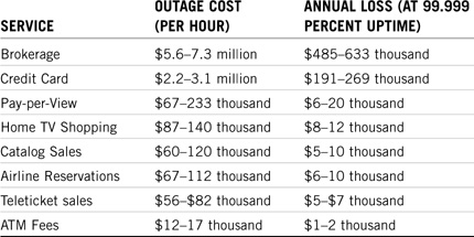
To achieve this level of high availability, you’ll have to recruit help from power vendors, application retailers, and a clustering consultant. Believe me, five 9s high availability does not come cheap. Table 14.1 compares five popular high availability quotients.

Although NCS provides all the software that you need to configure a high availability clustering solution, many other factors might affect your high availability quotient. The following factors can cause computer system outages at anytime:
![]() Physical—Physical faults are hardware failures in your network system. This includes temperature, air quality, and network magnetism. A good rule of thumb is that if you’re comfortable in a room, computers are probably comfortable as well. However, certain simple precautions must be taken in the physical environment to protect network components.
Physical—Physical faults are hardware failures in your network system. This includes temperature, air quality, and network magnetism. A good rule of thumb is that if you’re comfortable in a room, computers are probably comfortable as well. However, certain simple precautions must be taken in the physical environment to protect network components.
![]() Design—Design errors in both the hardware and software subsystems can cause a network to fail. You should be particularly sensitive to the design of cluster-enabled components.
Design—Design errors in both the hardware and software subsystems can cause a network to fail. You should be particularly sensitive to the design of cluster-enabled components.
![]() Operations—Users can be your network’s biggest enemy. Errors caused by operations personnel or users themselves can cause computer systems to fail. In this case, education is the key to high availability. For example, you should proactively educate your users that the CD-ROM tray is not a cup holder and email worms are bad. This will improve the availability of your disk subsystems.
Operations—Users can be your network’s biggest enemy. Errors caused by operations personnel or users themselves can cause computer systems to fail. In this case, education is the key to high availability. For example, you should proactively educate your users that the CD-ROM tray is not a cup holder and email worms are bad. This will improve the availability of your disk subsystems.
![]() Environmental—In addition to the physical environment, you might have to be concerned about static electricity, lightning, electromagnetic interference (EMI), and other power anomalies. As if that’s not enough, your external network connections can fail because of natural disasters and so on.
Environmental—In addition to the physical environment, you might have to be concerned about static electricity, lightning, electromagnetic interference (EMI), and other power anomalies. As if that’s not enough, your external network connections can fail because of natural disasters and so on.
![]() Reconfiguration—Scheduled maintenance, upgrades, or configuration changes can also bring networks down.
Reconfiguration—Scheduled maintenance, upgrades, or configuration changes can also bring networks down.
Of course, all of these computer system outage factors are exaggerated when they converge on a single point of failure. Try to avoid this disastrous situation by building fault tolerance and redundancy into all your network components.
So, how highly available do you want to be? It really depends on what business you’re in and how valuable your data is. Table 14.2 shows the thousands (and sometimes millions) of dollars that are lost every time your network fails. In many of these cases, Novell Cluster Services is more than a nice thing to have—it’s job security.
Novell Cluster Services 1.6 is not a magic pill for 100% high availability. It is, however, a major leap toward five 9s. NCS helps you avoid all network outages caused by the NetWare server. In addition, it covers any hardware outages associated with the server’s power, internal components, or storage devices. This is accomplished by a zero MTTR failover from one server to another. And, miraculously enough, all files and applications are maintained because both servers share a common disk system.
The most impressive benefits and features provided by NCS 1.6 are
![]() Multinode all-active cluster (up to 32 nodes)—NCS enables you to configure up to 32 NetWare servers (nodes) into a high availability cluster, where resources can be dynamically switched or moved to any server at anytime. Furthermore, services can be assigned across the cluster to different services. This means that any NetWare server in the cluster can instantly restart resources from a failed server. This helps NCS achieve an MTTR of zero.
Multinode all-active cluster (up to 32 nodes)—NCS enables you to configure up to 32 NetWare servers (nodes) into a high availability cluster, where resources can be dynamically switched or moved to any server at anytime. Furthermore, services can be assigned across the cluster to different services. This means that any NetWare server in the cluster can instantly restart resources from a failed server. This helps NCS achieve an MTTR of zero.
![]() Multiprocessor and multithreading enabled—Because NCS 1.6 sits on a NetWare 6 platform, it is both multiprocessor and multithreaded enabled. That means each processor can be maximized to execute commands faster and more efficiently, providing faster network throughput that delivers 24×7×365 availability.
Multiprocessor and multithreading enabled—Because NCS 1.6 sits on a NetWare 6 platform, it is both multiprocessor and multithreaded enabled. That means each processor can be maximized to execute commands faster and more efficiently, providing faster network throughput that delivers 24×7×365 availability.
![]() Consolidation of applications and operations—NCS enables you to tailor a cluster to the specific applications and hardware infrastructure that fit your organization’s needs. You can also reduce unplanned and planned outages by offloading services to nonactive nodes. This means that you can reduce the number of servers needed to provide your services by 50% or more.
Consolidation of applications and operations—NCS enables you to tailor a cluster to the specific applications and hardware infrastructure that fit your organization’s needs. You can also reduce unplanned and planned outages by offloading services to nonactive nodes. This means that you can reduce the number of servers needed to provide your services by 50% or more.
![]() Flexible resource management—You can configure resources to switch to an active node automatically when a server fails, or you can move services manually to troubleshoot hardware or balance the workload. This flexible resource management enables you to optimize the resources you’re using to deliver highly available services.
Flexible resource management—You can configure resources to switch to an active node automatically when a server fails, or you can move services manually to troubleshoot hardware or balance the workload. This flexible resource management enables you to optimize the resources you’re using to deliver highly available services.
![]() Shared storage support—NCS provides support for shared SCSI devices or for Fiber Channel SANs. In addition, you can achieve shared disk fault tolerance by implementing RAID Level 5. Refer to Chapter 12, “Advanced Novell Storage Management,” for a more detailed explanation of RAID levels.
Shared storage support—NCS provides support for shared SCSI devices or for Fiber Channel SANs. In addition, you can achieve shared disk fault tolerance by implementing RAID Level 5. Refer to Chapter 12, “Advanced Novell Storage Management,” for a more detailed explanation of RAID levels.
![]() Single point of control—NCS 1.6 enables you to manage a cluster from a single point of control by using ConsoleOne or NetWare Remote Manager. In fact, the browser-based NetWare Remote Manager enables you to load balance network services across the cluster from a remote location.
Single point of control—NCS 1.6 enables you to manage a cluster from a single point of control by using ConsoleOne or NetWare Remote Manager. In fact, the browser-based NetWare Remote Manager enables you to load balance network services across the cluster from a remote location.
![]() Fan-out failover—Based on factors such as node traffic and availability of installed applications, you can configure migration and load balancing of resources to other nodes during a failover. The network administrator (or clustering consultant) configures fan-out failure for the cluster.
Fan-out failover—Based on factors such as node traffic and availability of installed applications, you can configure migration and load balancing of resources to other nodes during a failover. The network administrator (or clustering consultant) configures fan-out failure for the cluster.
![]() Cluster event and state notification—You can configure NCS 1.6 to notify administrators through email when cluster states change. This is a critical component of your high availability maintenance and notification procedures.
Cluster event and state notification—You can configure NCS 1.6 to notify administrators through email when cluster states change. This is a critical component of your high availability maintenance and notification procedures.
Now that you’ve gained a greater appreciation for the meaning of high availability and have mastered the fundamentals of NCS, let’s learn how to design a highly available system of our own.
Test Objective Covered:
![]() Design and Set Up an NCS Cluster Configuration
Design and Set Up an NCS Cluster Configuration
Before you can build it, you must design it.
As with any complex network system, you must design a high availability architecture before you can install NCS 1.6. Designing Novell Cluster Services is a marriage between typical network design and atypical NCS architecture design. On the typical side, NCS design requires minimum server requirements, high capacity network planning, and load balancing. On the other hand, a typical NCS design involves Fiber Channel or SCSI cluster configurations, NCS system design, and SAN management.
In this lesson, we’ll focus on the atypical design components specific to NCS high availability. We’ll begin with a discussion of the NCS basic system architecture and then quickly expand into the area of NCS system design. In the primary section of this lesson, you’ll learn about cluster-enabled volumes and pools, fan-out failover, and a detailed process of casting off failed nodes in a cluster. We’ll complete the lesson with a quick overview of SAN management and troubleshooting.
So, without any further ado, let’s begin our NCS design lesson with a peek at the basic NCS system architecture.
The basic clustering system architecture involves two or more servers, NCS 1.6 software installed on each server, a shared disk system, and a high-speed channel between them all. Figure 14.1 provides an illustration of this basic architecture.
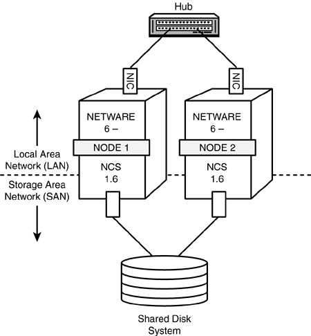
Actually, the NCS system architecture is much more complex than what is shown in Figure 14.1. Let’s take a moment to review the NCS cluster vocabulary.
To fully appreciate and understand the complexity of the NCS architecture, you should be familiar with the following clustering terms:
![]() Cluster—A group of servers linked together in a dedicated network to minimize the loss of service by reducing or managing failures and minimizing downtime.
Cluster—A group of servers linked together in a dedicated network to minimize the loss of service by reducing or managing failures and minimizing downtime.
![]() Node—A server in a cluster. Remember that NCS 1.6 supports up to 32 nodes in a single cluster.
Node—A server in a cluster. Remember that NCS 1.6 supports up to 32 nodes in a single cluster.
![]() Cluster resource—A server resource, such as an application or network service, with a dynamic location managed by NCS. Remember that a cluster resource is assignable to only one node at a time in NCS.
Cluster resource—A server resource, such as an application or network service, with a dynamic location managed by NCS. Remember that a cluster resource is assignable to only one node at a time in NCS.
![]() Shared storage device—A device, such as an external hard drive, that hosts shared cluster resources. In most instances, this is the shared disk system that I’ve been speaking of.
Shared storage device—A device, such as an external hard drive, that hosts shared cluster resources. In most instances, this is the shared disk system that I’ve been speaking of.
![]() Storage area network (SAN)—A dedicated network connecting servers and shared storage devices. In NCS 1.6, a cluster is analogous to a SAN.
Storage area network (SAN)—A dedicated network connecting servers and shared storage devices. In NCS 1.6, a cluster is analogous to a SAN.
![]() Migration—The process of moving resources from one node to another within a cluster. Migration differs from failover in that it occurs before a server fails. Migration is useful for tasks such as load balancing of resources and upgrading servers in a cluster.
Migration—The process of moving resources from one node to another within a cluster. Migration differs from failover in that it occurs before a server fails. Migration is useful for tasks such as load balancing of resources and upgrading servers in a cluster.
![]() Failover—The automatic migration of resources after a node fails. Failover normally results from a server hardware or power source problem, and is unplanned. Anything else is a migration.
Failover—The automatic migration of resources after a node fails. Failover normally results from a server hardware or power source problem, and is unplanned. Anything else is a migration.
![]() Fan-out failover—Load balancing of the migration of resources to other nodes during a failover, based on factors such as node traffic and availability of installed applications. In NCS clustering, you can configure fan-out failure options to optimize resource load balancing. Fan-out failover is also known as intelligent failover.
Fan-out failover—Load balancing of the migration of resources to other nodes during a failover, based on factors such as node traffic and availability of installed applications. In NCS clustering, you can configure fan-out failure options to optimize resource load balancing. Fan-out failover is also known as intelligent failover.
![]() Failback—The process of returning a failed node’s resources back to the way they were before the failover. Of course, failback implies that the original cause of the failure has been remedied.
Failback—The process of returning a failed node’s resources back to the way they were before the failover. Of course, failback implies that the original cause of the failure has been remedied.
![]() Fibre Channel—The Fibre Channel Standard (FCS) defines a high-speed data transfer interface for workstations, mainframes, supercomputers, storage devices, and displays. By using FCS, you can build a very fast and reliable NCS cluster. Fibre Channel supports a variety of optical and electrical media with data transfer rates from 260 megabits per second (copper wire) up to 4 gigabits per second (fiber optics). Furthermore, Fibre Channel with fiber optics supports very long connections—up to 10 km (6.2 miles).
Fibre Channel—The Fibre Channel Standard (FCS) defines a high-speed data transfer interface for workstations, mainframes, supercomputers, storage devices, and displays. By using FCS, you can build a very fast and reliable NCS cluster. Fibre Channel supports a variety of optical and electrical media with data transfer rates from 260 megabits per second (copper wire) up to 4 gigabits per second (fiber optics). Furthermore, Fibre Channel with fiber optics supports very long connections—up to 10 km (6.2 miles).
Now that you’re a pro with NCS nomenclature, let’s explore the four basic components that make up our cluster system architecture.
The four components that make up a NetWare 6 NCS cluster are
![]() NetWare 6 servers—You must have two or more NetWare 6 servers configured to communicate with each other via TCP/IP. In addition, each server must have at least one local disk device used for the SYS volume. NCS 1.6 supports up to 32 NetWare 6 servers in a single cluster.
NetWare 6 servers—You must have two or more NetWare 6 servers configured to communicate with each other via TCP/IP. In addition, each server must have at least one local disk device used for the SYS volume. NCS 1.6 supports up to 32 NetWare 6 servers in a single cluster.
![]() NCS 1.6—You must install the Novell Cluster Services 1.6 software on each server in the cluster. In addition, NCS 1.6 runs on the NetWare 6 platform; therefore, you must also install NetWare 6 on each server in the cluster.
NCS 1.6—You must install the Novell Cluster Services 1.6 software on each server in the cluster. In addition, NCS 1.6 runs on the NetWare 6 platform; therefore, you must also install NetWare 6 on each server in the cluster.
![]() Shared disk system—The whole point of clustering is multinode access to a shared disk system. This is the cornerstone component of NCS 1.6.
Shared disk system—The whole point of clustering is multinode access to a shared disk system. This is the cornerstone component of NCS 1.6.
NOTE
A number of NetWare services do not require a shared disk system including Novell Licensing, LDAP Server, and DHCP.
![]() NCS communications platform—NCS 1.6 provides two options for communications between cluster nodes and the shared disk system. Your two choices are Fiber Channel (recommended) and SCSI. Refer to the next section for a description of these two NCS cluster configurations.
NCS communications platform—NCS 1.6 provides two options for communications between cluster nodes and the shared disk system. Your two choices are Fiber Channel (recommended) and SCSI. Refer to the next section for a description of these two NCS cluster configurations.
These are the four basic components that make up the cluster system architecture.
In NCS, the server (node) acts as a midpoint between two networks: LAN (local area network) and SAN (storage area network). LAN communications are accomplished via an internal server NIC (network interface card) and Ethernet cabling through a central network hub. This half of the NCS cluster communications equation operates the same way it operates for any Novell network. SAN communications, on the other hand, are the cornerstone of Novell clustering. In a Fiber Channel configuration, SAN communications are accomplished via a Fiber Channel card in each server. Furthermore, these cards are connected to a shared storage device via a Fiber Channel switch. NCS 1.6 supports two basic SAN cluster configurations:
![]() Fiber Channel
Fiber Channel
![]() SCSI
SCSI
Figure 14.2 illustrates a typical Fiber Channel cluster configuration. This configuration defines two levels of communication: LAN communication via Ethernet NICs and SAN communications via Fiber Channel cards (FC).
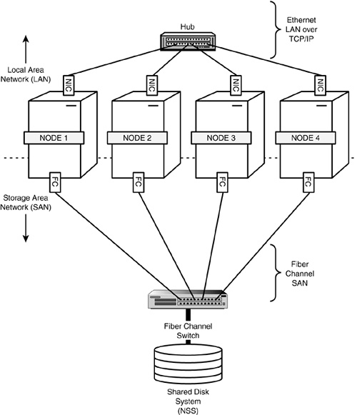
The interesting thing about the Fiber Channel architecture is that it supports both copper and fiber-optic cabling. In fact, Fiber Channel is an architecture standard protocol for transmitting data at very high speeds within a SAN. Fiber Channel cards are sometimes called host bus adaptors (HBAs).
Although Fiber Channel is the recommended cluster configuration, you can also use a dedicated SCSI hardware architecture. Figure 14.3 illustrates the SCSI hard drive cluster configuration. In some non-mission–critical environments (such as testing and demos), you can configure a small two-node cluster to use an external shared SCSI hard drive. Remember: This is not a recommended configuration for production cluster systems.

In this cluster configuration, an Ethernet NIC handles LAN communications and SAN communications operate over SCSI adapter cards and high-speed cables. If you use SCSI cards and a SCSI hard drive to configure a two-node cluster, make sure that the hard drive and each card are assigned different SCSI ID numbers.
That completes our basic discussion of clustering system architecture. I hope that I’ve clarified any questions you have regarding NCS cluster vocabulary, the components that make up a clustering system, and the two cluster configurations supported by NCS 1.6: Fiber Channel and SCSI.
To build a reliable high availability solution with NCS 1.6, you must understand how all the different components communicate with each other. We’ll use the Fiber Channel architecture to explore the detailed operation of Novell Cluster Services in this section. During this system design discussion, I’ll describe the activities of five very important NCS components:
![]() Master node—The first server that is enabled in an NCS cluster is assigned the cluster IP address and becomes the master node. The master node updates information transmitted between the cluster and eDirectory, and monitors the health of the other cluster nodes. If the master node fails, NCS migrates the cluster IP address to another server in the cluster and that server becomes the master node.
Master node—The first server that is enabled in an NCS cluster is assigned the cluster IP address and becomes the master node. The master node updates information transmitted between the cluster and eDirectory, and monitors the health of the other cluster nodes. If the master node fails, NCS migrates the cluster IP address to another server in the cluster and that server becomes the master node.
![]() Slave nodes—All servers in an NCS cluster, except the master node, are referred to as slave nodes. Slave nodes receive instructions from the master node and wait patiently in case the master node fails.
Slave nodes—All servers in an NCS cluster, except the master node, are referred to as slave nodes. Slave nodes receive instructions from the master node and wait patiently in case the master node fails.
![]() Cluster resource—A cluster resource is an object in eDirectory that represents an application or other type of service that you can migrate or failover from one node to another in NCS. This resource could be an email application, DHCP server, master IP address, or anything else that eDirectory supports. It’s important that each cluster resource have, in eDirectory, an accompanying object that includes scripts for unloading the service from one node and loading it to another. Also you must make sure that the Cluster Resource service itself is installed on all nodes in the cluster that will host it.
Cluster resource—A cluster resource is an object in eDirectory that represents an application or other type of service that you can migrate or failover from one node to another in NCS. This resource could be an email application, DHCP server, master IP address, or anything else that eDirectory supports. It’s important that each cluster resource have, in eDirectory, an accompanying object that includes scripts for unloading the service from one node and loading it to another. Also you must make sure that the Cluster Resource service itself is installed on all nodes in the cluster that will host it.
![]() Shared storage device—The shared storage device is the cornerstone of the NCS SAN. This is where all the users’ files are stored. By moving all files to a shared storage device, you can reduce the number of servers needed in your network and reserve files on the local node drive for network administration. Remember that each node must have a local SYS: volume that isn’t shared for operating system files and utilities.
Shared storage device—The shared storage device is the cornerstone of the NCS SAN. This is where all the users’ files are stored. By moving all files to a shared storage device, you can reduce the number of servers needed in your network and reserve files on the local node drive for network administration. Remember that each node must have a local SYS: volume that isn’t shared for operating system files and utilities.
![]() Cluster-enabled volumes and pools—A cluster-enabled volume is a NetWare 6 NSS volume that gives users continuous read/write file access on the shared storage device. Furthermore, NetWare 6 enables you to cluster-enable storage pools. This makes it possible for you to migrate or failover more than one volume at a time. With NetWare 6 clustering, volumes are associated with NSS pools that provide a unique secondary Internet Protocol (IP) address (through a virtual server object) for locating the volumes on the cluster’s shared storage device.
Cluster-enabled volumes and pools—A cluster-enabled volume is a NetWare 6 NSS volume that gives users continuous read/write file access on the shared storage device. Furthermore, NetWare 6 enables you to cluster-enable storage pools. This makes it possible for you to migrate or failover more than one volume at a time. With NetWare 6 clustering, volumes are associated with NSS pools that provide a unique secondary Internet Protocol (IP) address (through a virtual server object) for locating the volumes on the cluster’s shared storage device.
In this section, you’ll learn how master and slave nodes monitor the LAN and SAN for cluster health. You’ll also learn how NCS handles slave node and master node failovers in case something unexpected happens. Finally, we’ll explore a specific design for load-balancing cluster resources using the fanout failover method.
Now it’s time to master NCS system design.
NCS uses two important mechanisms for monitoring the health of communications on the LAN and the SAN: heartbeats and SBD. The goal of this monitoring strategy is to ensure high availability of cluster resources on both the LAN and SAN segments. The following is a brief description of how NCS monitors the health of LANs and SANs:
![]() Monitoring the LAN—NCS uses heartbeats to monitor the health of nodes on the LAN. A heartbeat is a small IP packet periodically sent over the LAN (not the SAN) by the master node and all slave nodes in the cluster. The master node sends out a multicast heartbeat to all slaves, and the slaves send a unicast response back to the master. All nodes in a cluster monitor the heartbeat of each other at a tolerance rate of eight seconds (default setting). The tolerance rate is the amount of time that a node waits for a heartbeat from another node before taking action that results in casting off a failed node.
Monitoring the LAN—NCS uses heartbeats to monitor the health of nodes on the LAN. A heartbeat is a small IP packet periodically sent over the LAN (not the SAN) by the master node and all slave nodes in the cluster. The master node sends out a multicast heartbeat to all slaves, and the slaves send a unicast response back to the master. All nodes in a cluster monitor the heartbeat of each other at a tolerance rate of eight seconds (default setting). The tolerance rate is the amount of time that a node waits for a heartbeat from another node before taking action that results in casting off a failed node.
![]() Monitoring the SAN—Simultaneously, NCS uses a split-brain detector (SBD) on the shared storage device to ensure that each node maintains membership in the cluster. A tic (transport-independent checking) is a type of heartbeat sent over the SAN by a node. SBD is implemented as a small dedicated disk partition on the shared disk. Each node in the cluster periodically writes an epoch number (through a tic) over the SAN (not the LAN) to the SBD partition on the shared storage device. Before writing its own epoch number, the node reads the epoch numbers of all other nodes in the cluster. This number increases by one each time a node leaves or joins the cluster. SBD is an important mechanism for monitoring the migration of nodes in and out of a given cluster.
Monitoring the SAN—Simultaneously, NCS uses a split-brain detector (SBD) on the shared storage device to ensure that each node maintains membership in the cluster. A tic (transport-independent checking) is a type of heartbeat sent over the SAN by a node. SBD is implemented as a small dedicated disk partition on the shared disk. Each node in the cluster periodically writes an epoch number (through a tic) over the SAN (not the LAN) to the SBD partition on the shared storage device. Before writing its own epoch number, the node reads the epoch numbers of all other nodes in the cluster. This number increases by one each time a node leaves or joins the cluster. SBD is an important mechanism for monitoring the migration of nodes in and out of a given cluster.
Once NCS has determined that there’s been a change in the availability of cluster resources from a given node, it can initiate a failover. Let’s take a closer look.
The following steps describe the detailed process of casting off a failed slave node in NCS:
1. Each node in the NCS cluster sends a heartbeat packet over the LAN at a preconfigured rate (one second by default).
2. Simultaneously each node also writes an epoch number to the SBD on the shared storage device. The epoch number is written at half the preconfigured tolerance rate of the heartbeat (four seconds by default).
3. The master node monitors the heartbeats of all other nodes in the cluster to determine whether they’re still alive. The master node also reads the epoch numbers for all nodes in the cluster.
4. If a heartbeat is not received from a slave node within eight seconds (the default tolerance rate), the master node and remaining slave nodes create a new cluster membership view. The new cluster membership view does not include the node that failed to communicate to the master node. That slave node has now been cast off. Furthermore, each node in the new view must update its epoch number by one because there has been a change in cluster membership.
5. Now there are two cluster membership views. The node that failed to send a heartbeat uses the old cluster membership view with the old epoch number. The other nodes use the new Cluster Membership View with a new Epoch Number. This causes a split-brain condition. NCS uses the information in SBD to vote between the two cluster membership views. The cluster membership view that has the most nodes wins. However, if there are equal nodes in both views, the side with the master node wins.
6. The nodes in the surviving cluster membership view write a special token to the SBD for the losing node. The losing node reads the special token and then abends (that is, has an abnormal ending) by taking a “poison pill.” Abending ensures that nodes on the losing side cannot corrupt the new, healthy cluster.
7. The new cluster migrates the resources assigned to the failed node to other nodes in the cluster and users are none the wiser. As a result, cluster services are uninterrupted and high availability is maintained.
The following steps describe the process of casting off a failed master node in NCS:
1. Each node in the NCS cluster sends a heartbeat packet over the LAN at a preconfigured rate (one second by default).
2. Simultaneously, each node also writes an epoch number to the SBD on the shared storage device. The epoch number is written at half the preconfigured tolerance rate of the heartbeat (four seconds by default).
3. The master node monitors the heartbeats of all other nodes in the cluster to determine whether they’re still alive. Simultaneously, each slave node in a cluster continuously monitors the heartbeat of the master node.
4. If the master node fails to send a heartbeat to the slaves within eight seconds (the default tolerance level), the slave nodes create a new cluster membership view. At the same time, the old cluster membership view is maintained by the master node. In addition, each node in the new cluster membership view increases its epoch number by one in the SBD partition.
5. Now there are two cluster membership views. The master node uses the old cluster membership view with the old epoch number. The other nodes use the new cluster membership view with a new epoch number. This causes a split-brain condition. NCS uses the information in SBD to vote between the two cluster membership views. The cluster membership view that has the most nodes wins. However, if there are equal nodes in both views, the side with the master node wins. Because the master node has a different cluster membership view and is the only node with a different epoch number, the new cluster membership view with the slave nodes wins.
6. The nodes in the new cluster membership view write a special token to the sector in SBD for the master node. The losing master node reads the special token and then it abends by taking a poison pill. At the same time, the slave nodes use an algorithm to vote on which node becomes the new master.
7. The new cluster (with a new master node) migrates all cluster resources (volumes and services) assigned to the previous master node and high availability is maintained. NCS and all of your users win again!
As you learned earlier, failover is the process of automatically migrating resources from a failed node to other slaves and masters in a cluster. Although this migration happens automatically, you must design and configure where each volume and cluster resource migrates during failover. Furthermore, you’ll probably want to distribute or fan out the volumes and resources to several nodes based on a variety of factors, including load balancing, network configuration, availability of installed applications, hardware platform, and so on.
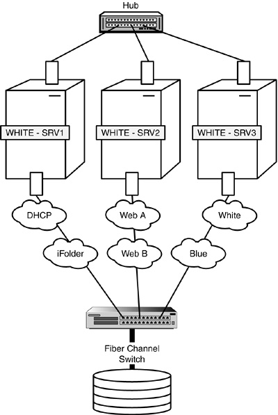
Although the process of fan-out failover is automatic, its design and configuration are not. Follow along by using Figures 14.4 and 14.5 as we walk through an example of designing fan-out failover for ACME. In Figure 14.4, the Tokyo location of ACME has a three-node Fiber Channel cluster of WHITE servers. During normal cluster operations, each server remains in constant communication with the others by sending out periodic heartbeats over the LAN. In addition, you can see that each server hosts specific network resources and services: WHITE-SRV1 hosts DHCP and iFolder, WHITE-SRV2 hosts two Web sites (A and B), and WHITE-SRV3 hosts two email servers (WHITE and BLUE).

One day, something catastrophic happens to WHITE-SRV3. Fortunately, you’ve preconfigured the WHITE NCS cluster for automatic fan-out failover.
Figure 14.5 illustrates the automatic fan-out failover of email services from WHITE-SRV3 to WHITE-SRV1 and WHITE-SRV2. During this automatic migration, the shared data volumes and email applications running on WHITE-SRV3 are restarted on WHITE-SRV1 (WHITE email services) and WHITE-SRV2 (BLUE email services). It’s important to note that these email services must already be installed on WHITE-SRV1 and WHITE-SRV2.
In this example, the email migration happens so quickly that users might not even notice. In most cases, they’ll lose email access for only a few seconds. When the problems with WHITE-SRV3 have been resolved, you can migrate both email services back to their original host server. This process, known as failback, can be accomplished manually or automatically. By default, NCS configures failback in manual mode. This gives you the opportunity to test the WHITE and BLUE email services on the newly restored WHITE-SRV3 before you make them live. You can, however, with a flip of a switch, configure NCS for automatic failback. This means WHITE-SRV3 will initiate its original email services as soon as it’s added back to the cluster.
TIP
NCS resources are configured with failback disabled by default. Because of this, you can bring a failed node back into the cluster and test its viability without resources automatically loading on the node. You can, however, set resources to automatically failback to a particular node when that node joins the cluster.
That completes our lesson in NCS system design. As you can see, this is a complex and sophisticated system. Believe me when I say that Novell Cluster Services is not for the faint of heart. However, the rewards are great! You’ll quickly gain hero status for maintaining five 9s availability on mission-critical systems.
Now let’s complete our NCS design lesson with a quick jaunt through SAN management.
Just as in life, rules in networking separate cluster services from storage chaos. In this section, we explore a number of storage area network (SAN) management and troubleshooting rules for maintaining an orderly cluster system.
TIP
To avoid such problems as assigning a local volume and a shared volume to the same pool, each shared storage device in NCS is assigned a global unique ID (GUID). A flag is set on the device to help NetWare 6 distinguish between local server storage devices and shared storage devices. If the server with the local volume fails, the shared volume is assigned another node, but the local volume remains inaccessible to users.
Let’s start with the following four guidelines for avoiding data corruption or volume loss:
![]() Noncluster servers—Don’t attach a noncluster server to a central shared storage device unless you isolate the system so that the noncluster server only has access to its own volumes. Remember that all servers attached to the shared storage device (whether in the cluster or not) have access to all volumes unless you specifically prevent such access. NCS manages access to shared volumes for all cluster nodes, but cannot protect shared volumes from being corrupted by noncluster servers.
Noncluster servers—Don’t attach a noncluster server to a central shared storage device unless you isolate the system so that the noncluster server only has access to its own volumes. Remember that all servers attached to the shared storage device (whether in the cluster or not) have access to all volumes unless you specifically prevent such access. NCS manages access to shared volumes for all cluster nodes, but cannot protect shared volumes from being corrupted by noncluster servers.
![]() NetWare 6 installation—Don’t install NetWare 6 on a server that’s currently attached to shared storage. You must disconnect the shared device from the server before you install NetWare. This rule is necessary because NetWare 6 installation deletes all NetWare partitions that it finds on local and shared storage devices. Imagine the chaos in your high availability solution if your NetWare partitions suddenly disappeared. Ouch.
NetWare 6 installation—Don’t install NetWare 6 on a server that’s currently attached to shared storage. You must disconnect the shared device from the server before you install NetWare. This rule is necessary because NetWare 6 installation deletes all NetWare partitions that it finds on local and shared storage devices. Imagine the chaos in your high availability solution if your NetWare partitions suddenly disappeared. Ouch.
![]() NSS cluster volume operations—Don’t perform NSS cluster volume operations (such as deleting, resizing, and renaming) from noncluster nodes.
NSS cluster volume operations—Don’t perform NSS cluster volume operations (such as deleting, resizing, and renaming) from noncluster nodes.
![]() Shared volumes—Don’t clutter the shared storage device with volumes that can be kept on local server drives. Only place volumes on shared storage that contain data or files that need to be shared by multiple users or multiple applications. This way you can keep your cluster uncluttered.
Shared volumes—Don’t clutter the shared storage device with volumes that can be kept on local server drives. Only place volumes on shared storage that contain data or files that need to be shared by multiple users or multiple applications. This way you can keep your cluster uncluttered.
In addition to SAN management, there are a number of rules that can help you troubleshoot SAN problems when they occur. Most problems in setting up a SAN result from errors in preparing and connecting devices on the SCSI bus. If you have problems with your SAN, use the following troubleshooting rules to check your configuration:
![]() Multi-initiator enabled—Is the SCSI adapter card and driver you are using multi-initiator enabled? (That is, can it support multiple host adapters on the same SCSI bus?) NCS requires this feature when attaching multiple nodes to a single shared device. To determine the capabilities of your SCSI adapter card and drivers, refer to the manufacturer’s Web site. Be aware that only a few third-party drivers support multi-initiation. Personally, I like to use the Adaptec 2940 adapter card with the Novell .HAM driver.
Multi-initiator enabled—Is the SCSI adapter card and driver you are using multi-initiator enabled? (That is, can it support multiple host adapters on the same SCSI bus?) NCS requires this feature when attaching multiple nodes to a single shared device. To determine the capabilities of your SCSI adapter card and drivers, refer to the manufacturer’s Web site. Be aware that only a few third-party drivers support multi-initiation. Personally, I like to use the Adaptec 2940 adapter card with the Novell .HAM driver.
![]() SCSI hardware installation—Make sure that all SCSI cables in the cluster have the same impedance and the same length, and that the same manufacturer built them. In addition, make sure that all SCSI devices are turned on and that the adapter cables and power are properly connected. Finally, confirm that the SCSI adapter card is seated securely in the motherboard of each cluster node.
SCSI hardware installation—Make sure that all SCSI cables in the cluster have the same impedance and the same length, and that the same manufacturer built them. In addition, make sure that all SCSI devices are turned on and that the adapter cables and power are properly connected. Finally, confirm that the SCSI adapter card is seated securely in the motherboard of each cluster node.
![]() Unique SCSI IDs—Each device in the SCSI bus (including adapter cards and hard drives) must have a unique SCSI ID number. Most SCSI hard drives are preset with an ID number of zero (0) and SCSI adapter cards are preset with an ID number of 7. If you’re using an external SCSI hard drive, the SCSI ID number is usually set with a switch on the back of the device. Finally, when configuring a two-node SCSI cluster for NCS, consider using 7 as the SCSI ID for one card and 6 for the other card. Even if higher ID numbers are available (such as 8 through 15), avoid using them with NCS.
Unique SCSI IDs—Each device in the SCSI bus (including adapter cards and hard drives) must have a unique SCSI ID number. Most SCSI hard drives are preset with an ID number of zero (0) and SCSI adapter cards are preset with an ID number of 7. If you’re using an external SCSI hard drive, the SCSI ID number is usually set with a switch on the back of the device. Finally, when configuring a two-node SCSI cluster for NCS, consider using 7 as the SCSI ID for one card and 6 for the other card. Even if higher ID numbers are available (such as 8 through 15), avoid using them with NCS.
![]() SCSI hard drive termination—To ensure reliable communication on the SCSI bus, the end devices must be properly terminated. For a two-node NCS SCSI cluster, each SCSI adapter must be terminated. Furthermore, the hard drive is not terminated because it sits in the middle of the SCSI bus system. Installing or removing a SCSI terminator plug controls termination on most SCSI hard drives. However, some hard drives allow you to enable and disable termination by using a switch on the back of the drive.
SCSI hard drive termination—To ensure reliable communication on the SCSI bus, the end devices must be properly terminated. For a two-node NCS SCSI cluster, each SCSI adapter must be terminated. Furthermore, the hard drive is not terminated because it sits in the middle of the SCSI bus system. Installing or removing a SCSI terminator plug controls termination on most SCSI hard drives. However, some hard drives allow you to enable and disable termination by using a switch on the back of the drive.
![]() SCSI hard drive low-level format—Every SCSI hard disk must be low-level formatted, partitioned, and logically formatted before it can store data. Most SCSI drives are preformatted at the factory. However, if you connect a used SCSI hard drive to the NCS nodes for clustering, you must perform a low-level format before you can use the drive. Because this process destroys all data on the drive, make sure that you back up the data before performing a low-level format. Finally, consider using the SCSI utility to configure various BIOS settings on your SCSI adapter card. See Table 14.3 for more details.
SCSI hard drive low-level format—Every SCSI hard disk must be low-level formatted, partitioned, and logically formatted before it can store data. Most SCSI drives are preformatted at the factory. However, if you connect a used SCSI hard drive to the NCS nodes for clustering, you must perform a low-level format before you can use the drive. Because this process destroys all data on the drive, make sure that you back up the data before performing a low-level format. Finally, consider using the SCSI utility to configure various BIOS settings on your SCSI adapter card. See Table 14.3 for more details.

Good job, you have successfully designed a sophisticated clustering system. In this lesson, you learned Novell’s basic clustering system architecture and explored Fiber Channel and SCSI configurations. In addition, we used heartbeats and split-brain detector to monitor the LAN and SAN. And with these tools in place, you learned how slave and master node failover works.
In the last section of this lesson, we armed ourselves with some important rules for SAN management and troubleshooting. I think you’re now ready for the real action: installing Novell Cluster Services. So far, you’ve mastered the fundamentals of NCS and designed a basic system architecture. Now let’s build one for ourselves.
Ready, set, cluster!
Test Objectives Covered:
![]() Verify NCS System Requirements
Verify NCS System Requirements
![]() Create a Cluster by Installing NCS
Create a Cluster by Installing NCS
![]() Check Cluster Configuration Settings
Check Cluster Configuration Settings
![]() Test and Monitor the Cluster
Test and Monitor the Cluster
It’s time for action!
After you’ve designed your cluster architecture via a Fiber or SCSI Channel and set up and configured your SAN, it’s time to install and test NCS on all your cluster nodes. The process of installing Novell Cluster Services involves the following four steps:
1. NCS system requirements—Before installing NCS, your system must meet a minimum set of hardware, software, and shared disk system requirements. In summary, all your nodes must be running NetWare 6, NCS 1.6, and support at least one local disk device for volume SYS:. In addition, the shared disk system must have at least 10MB of free disk space available for the SBD partition.
2. NCS installation—The NCS installation program uses NetWare Deployment Manager. NWDEPLOY.EXE creates a cluster object in eDirectory and installs NCS 1.6 on all the servers in your cluster. Fortunately, NetWare 6 includes the NCS 1.6 software and licensing for a two-node cluster.
3. NCS configuration—After you’ve created a new cluster and installed NCS 1.6, it’s time for configuration. You’ll use ConsoleOne or NetWare Remote Manager to configure these four cluster objects: Cluster Admin, the Cluster object itself, Master IP Address Resource, and each cluster server node.
4. NCS testing and monitoring—Finally, with all the cluster nodes installed and configured correctly, you can shift your attention to NCS testing and monitoring. We’ll use ConsoleOne and NetWare Remote Manager to monitor a variety of cluster status views. In addition, NetWare 6 provides several server console commands for viewing the cluster status and managing your new cluster.
So, without any further ado, let’s put all this great new cluster knowledge to the test and install Novell Cluster Services.
In step 1 of an NCS installation, you must gather all of your clustering hardware and software and build the basic system architecture. To achieve NetWare 6 high availability with NCS, your cluster hardware must meet the following minimum system requirements:
![]() Two (or more) NetWare 6 servers; NCS 1.6 supports up to 32 servers in a single cluster.
Two (or more) NetWare 6 servers; NCS 1.6 supports up to 32 servers in a single cluster.
![]() At least 256MB of memory on all servers in the cluster (512MB is recommended for multiple application failover to the same server).
At least 256MB of memory on all servers in the cluster (512MB is recommended for multiple application failover to the same server).
![]() One local disk device (not shared) for SYS: on each server.
One local disk device (not shared) for SYS: on each server.
![]() A Network Interface Card (NIC) in each server and appropriate cabling for LAN communications.
A Network Interface Card (NIC) in each server and appropriate cabling for LAN communications.
![]() An FC or SCSI adapter card in each server and appropriate cabling for SAN communications. If you’re using a SCSI configuration, the external SCSI hard drive and each SCSI adapter card must have a unique SCSI ID.
An FC or SCSI adapter card in each server and appropriate cabling for SAN communications. If you’re using a SCSI configuration, the external SCSI hard drive and each SCSI adapter card must have a unique SCSI ID.
In addition to the hardware requirements just mentioned, you must make sure that all your NCS nodes are running the following minimum software components:
![]() NetWare 6 must be running on each node in the cluster. In addition, all cluster servers must be in the same eDirectory tree.
NetWare 6 must be running on each node in the cluster. In addition, all cluster servers must be in the same eDirectory tree.
![]() All servers in the cluster must be configured for IP and on the same IP subnet. Unfortunately, NCS is not IPX compatible.
All servers in the cluster must be configured for IP and on the same IP subnet. Unfortunately, NCS is not IPX compatible.
![]() Additional IP addresses are required for the following cluster components: one for the cluster itself, one (or more) for each cluster resource, and one (or more) for each cluster-enabled volume. The IP address assigned to each cluster resource is a secondary IP address that NCS uses to find and migrate the resource from one node to another in the cluster. If a service already has an IP address, that address is preserved as part of the service when you cluster-enable the service. It is not used as a resource secondary IP address for clustering.
Additional IP addresses are required for the following cluster components: one for the cluster itself, one (or more) for each cluster resource, and one (or more) for each cluster-enabled volume. The IP address assigned to each cluster resource is a secondary IP address that NCS uses to find and migrate the resource from one node to another in the cluster. If a service already has an IP address, that address is preserved as part of the service when you cluster-enable the service. It is not used as a resource secondary IP address for clustering.
In addition to minimum hardware and software requirements, NCS installation depends on the correct configuration of your shared disk system. The minimum requirements for your shared disk are
![]() At least 15MB of free disk space must be available on the shared disk for creating the SBD partition. NCS installation allocates one cylinder on one drive of the shares for this special cluster partition. If the drive where the cluster partition will be created is larger than 10GB, you might need more than 15MB of free disk space to allocate an entire cylinder.
At least 15MB of free disk space must be available on the shared disk for creating the SBD partition. NCS installation allocates one cylinder on one drive of the shares for this special cluster partition. If the drive where the cluster partition will be created is larger than 10GB, you might need more than 15MB of free disk space to allocate an entire cylinder.
![]() All NetWare servers in your cluster must recognize the shared disk system. Prior to installation, verify this by entering LIST DEVICES on each server that you’ll add to the cluster. If any drives in the shared disk system don’t show up in the list, you cannot continue with NCS installation until the problem has been remedied.
All NetWare servers in your cluster must recognize the shared disk system. Prior to installation, verify this by entering LIST DEVICES on each server that you’ll add to the cluster. If any drives in the shared disk system don’t show up in the list, you cannot continue with NCS installation until the problem has been remedied.
![]() The disks contained in the shared disk system must be configured in a RAID 1 (mirroring) or RAID 5 configuration to add fault tolerance.
The disks contained in the shared disk system must be configured in a RAID 1 (mirroring) or RAID 5 configuration to add fault tolerance.
After your NCS system has been built according to these specifications, it’s time to create a cluster. Now let’s continue with step 2: NCS installation.
Now it’s time to create our new NCS cluster. As you know, NCS 1.6 is integrated with NetWare 6. After you have installed NetWare 6 on all your cluster nodes, you can cluster them together using the NCS installation program. This program, via NetWare Deployment Manager, creates a cluster object in eDirectory and installs NCS 1.6 on all servers in your cluster. In addition, the NCS installation program enables you to add servers to your cluster later or upgrade NCS software from a previous version.
To install NCS 1.6 and create a new cluster, perform the following steps:
1. Insert the NetWare 6 CD-ROM in a NetWare workstation and allow NetWare Deployment Manager to launch. (You can also access this tool by running NWDEPLOY.EXE from the root of the CD-ROM.) Next, open the Post-Installation Tasks folder and select Install or Upgrade a Novell Cluster by double-clicking it. See Figure 14.6 for more information. When the Welcome screen appears, click Next to continue.

TIP
If the disks in your shared disk system are not configured for RAID 1 (mirroring) or RAID 5 (striping with parity), a single disk error can cause a volume failure. Remember that NCS does not protect against such faults. NCS is a high availability solution for protecting against server crashes, not shared disk crashes. That’s why you should always employ extra care in building fault tolerance around your shared disk system.
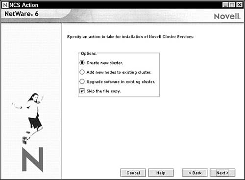
2. The NCS Action screen appears as shown in Figure 14.7. This screen enables you to choose one of three paths for NCS installation: create a new cluster, add a node to an existing cluster, or upgrade NCS software in an existing cluster. In addition, the Skip the File Copy option is useful if NCS files have already been copied to cluster nodes and you want to save time. For example, the NetWare 6 installation program already copies all NCS files to every NetWare 6 server. And because you’ve already installed NetWare 6 on all the nodes, you don’t need to copy the NCS files again. To create a new cluster, select the Create New Cluster radio button and click Next.
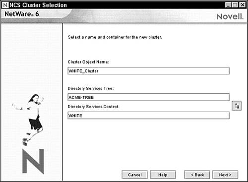
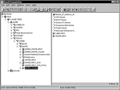
3. The NCS Cluster Selection screen appears as shown in Figure 14.8. Enter the name for the cluster object you’re creating and specify the eDirectory tree and context where you want it created. Remember that eDirectory uses the cluster object to track configuration settings for nodes and cluster resources. Typically, you should identify the host container object within the cluster name. In this example, I’m using WHITE_Cluster. Click Next to continue.
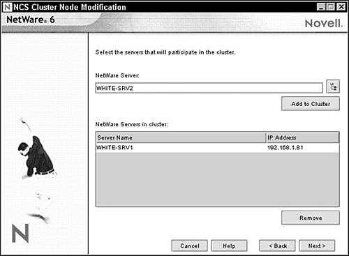
4. The NCS Cluster Node Modification screen appears as shown in Figure 14.9. In this form, you’ll use the NetWare Server field to add nodes to your new cluster. First, select the Browse button on the right side of the field and find the server. Click Add to begin defining nodes for your new cluster. Notice that all the new cluster servers appear in the NetWare Servers in Cluster list. When you add a server to a new cluster, the NCS installation program detects the server name and IP address automatically. If your server has more than one IP address, you’ll be prompted to select the one you want to use. Finally, click Next to continue.
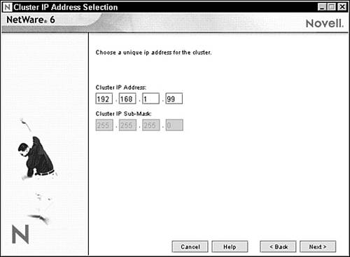
5. The Cluster IP Address Selection screen appears as shown in Figure 14.10. At this point, you must enter a unique IP address for the cluster. The cluster IP address is separate from any other IP address and is required for external programs to identify cluster status alerts. The cluster IP address is assigned to the master node and remains with the master node regardless of which server is assigned that special status. After you’ve defined the cluster IP address, click Next to continue.
6. The NCS Shared Media Selection screen appears. In this screen, you specify whether your cluster has a shared disk system and, if it does, you select the drive where you want the special SBD partition created. You’re also given the option of mirroring the partition for greater fault tolerance. When you’re done, click Next to continue.
7. The Start Clustering screen appears as shown in Figure 14.11. Now you can configure each node to start clustering automatically when installation is complete. Choose the Start Clustering radio button and click Next to continue.

8. At this point in the installation, NetWare Deployment Manager might ask you for the location of the license files. This screen appears only if you’re installing or creating a three-node or larger cluster. Because NetWare 6 includes a two-node cluster license by default, you probably won’t see this screen. Additionally, you can install NCS without licenses and it will automatically activate two nodes. If you want to add more nodes later, you must manually install the licenses by using Novell iManager.
9. After the NCS installation program has recognized the license, the Summary screen appears. Novell Cluster Services should be listed as the product to be installed. Begin the installation process by selecting Finish.
10. The NCS installation program creates a Cluster object in eDirectory and installs NCS 1.6 on all servers in your cluster. During installation, several clustering NLMs are loaded on each server, including NISP.NLM, NCSPROXY.NLM, and SBDLIB.NLM. When installation is complete, the Cluster Membership Monitor is displayed on each server listing the node with an UP status.
Hooray! You’ve used NCS 1.6 to create a multinode cluster. Believe it or not, you’re not done. Before you can claim that your network is highly available, you must configure your new NCS components and test them.
When you install NCS 1.6, several Cluster objects are created in eDirectory. During step 3 of NCS installation, you must use ConsoleOne or NetWare Remote Manager to configure a variety of settings for each of these objects. Here’s a preview of the four cluster objects that we’ll configure in this section:
![]() Cluster object—The NCS Cluster object contains most of the critical properties for NCS operation. In addition, the Cluster object houses the master IP address resource, cluster server nodes, and resource templates. This is the “father” of NCS eDirectory integration.
Cluster object—The NCS Cluster object contains most of the critical properties for NCS operation. In addition, the Cluster object houses the master IP address resource, cluster server nodes, and resource templates. This is the “father” of NCS eDirectory integration.
![]() Master IP Address Resource object—The Master IP Address Resource object contains a variety of scripts and policies for node failover and failback. In addition, this object allows the cluster to advertise on the LAN as if it were a virtual server.
Master IP Address Resource object—The Master IP Address Resource object contains a variety of scripts and policies for node failover and failback. In addition, this object allows the cluster to advertise on the LAN as if it were a virtual server.
![]() Cluster Server Node objects—When you install NCS 1.6, a Cluster Server Node object is created for every server in your cluster. By using this object, you can view or edit the cluster server node number, IP address, and view the context of the host NetWare server.
Cluster Server Node objects—When you install NCS 1.6, a Cluster Server Node object is created for every server in your cluster. By using this object, you can view or edit the cluster server node number, IP address, and view the context of the host NetWare server.
![]() Cluster ADMIN object—In addition to these three paramount Cluster objects, NCS creates an ADMIN object (such as ADMIN_WHITE-CLUSTER) for NCS configuration. This specialized ADMIN enables you to configure attributes, trustees, and rights for Cluster objects. It also enables you to set policies and specific operational parameters. By default, the Cluster ADMIN object is placed in the same eDirectory container as the Cluster object itself.
Cluster ADMIN object—In addition to these three paramount Cluster objects, NCS creates an ADMIN object (such as ADMIN_WHITE-CLUSTER) for NCS configuration. This specialized ADMIN enables you to configure attributes, trustees, and rights for Cluster objects. It also enables you to set policies and specific operational parameters. By default, the Cluster ADMIN object is placed in the same eDirectory container as the Cluster object itself.
Now let’s take a closer look at NCS configuration by exploring the properties of the three Cluster objects just listed.
The Cluster object is the cornerstone of NCS and eDirectory integration. As such, it behaves as both a leaf and container object (check it out in Figure 14.12). As a leaf, the Cluster object includes five key properties for NCS operation. As a container, the Cluster object houses all the Cluster Server Node and Cluster Resource objects.
The following is a description of the five main configuration properties included in the NCS Cluster object:
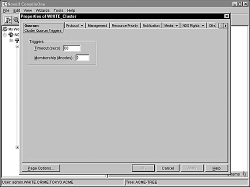
![]() Timeout and quorum membership—When you first start a cluster, NCS waits for a specific amount of time and for a specific number of nodes to join before it starts. The specific number of nodes is called a quorum. You can configure the timeout and quorum membership properties of a Cluster object by selecting the Quorum tab within the Properties option of ConsoleOne (see Figure 14.13). Quorum Timeout is the amount of time NCS will wait for the number of servers defined in the quorum membership before the cluster starts. If the timeout period elapses before the quorum membership reaches its specified number, resources will begin running on the servers that are currently enabled in the cluster. Quorum Membership is a related property that defines the number of nodes that must be running in the cluster before resources start to load. You must set the Quorum Membership property to a number greater than one so that all resources don’t load on the first server brought up in the cluster.
Timeout and quorum membership—When you first start a cluster, NCS waits for a specific amount of time and for a specific number of nodes to join before it starts. The specific number of nodes is called a quorum. You can configure the timeout and quorum membership properties of a Cluster object by selecting the Quorum tab within the Properties option of ConsoleOne (see Figure 14.13). Quorum Timeout is the amount of time NCS will wait for the number of servers defined in the quorum membership before the cluster starts. If the timeout period elapses before the quorum membership reaches its specified number, resources will begin running on the servers that are currently enabled in the cluster. Quorum Membership is a related property that defines the number of nodes that must be running in the cluster before resources start to load. You must set the Quorum Membership property to a number greater than one so that all resources don’t load on the first server brought up in the cluster.
![]() Cluster Protocol—You can configure the Cluster Protocol properties of the Cluster object by using the Protocol tab within the Properties Option of ConsoleOne. The resulting Cluster Protocol Settings form includes five parameters:
Cluster Protocol—You can configure the Cluster Protocol properties of the Cluster object by using the Protocol tab within the Properties Option of ConsoleOne. The resulting Cluster Protocol Settings form includes five parameters:
![]() Heartbeat defines the amount of time, in seconds, between LAN transmissions for all nodes.
Heartbeat defines the amount of time, in seconds, between LAN transmissions for all nodes.
![]() Tolerance defines the amount of time, in seconds, that the master node gives all other nodes in the cluster to signal that they are alive.
Tolerance defines the amount of time, in seconds, that the master node gives all other nodes in the cluster to signal that they are alive.
![]() Master Watchdog defines the amount of time, in seconds, between LAN transmissions from the master node to all other nodes in the cluster.
Master Watchdog defines the amount of time, in seconds, between LAN transmissions from the master node to all other nodes in the cluster.
![]() Slave Watchdog defines the master node tolerance, in seconds, until all slave nodes in the cluster cast off the master.
Slave Watchdog defines the master node tolerance, in seconds, until all slave nodes in the cluster cast off the master.
![]() Max Retransmits defines the number of times the master node waits for a heartbeat from another node before casting it off from the cluster.
Max Retransmits defines the number of times the master node waits for a heartbeat from another node before casting it off from the cluster.
![]() Cluster IP Address and Port—You can configure the Cluster IP Address and Port properties of your Cluster object by using the Management tab within the Properties option of ConsoleOne. When you install NCS, you assign an IP address to the cluster. This address normally does not need to be changed, but it can be changed if necessary. In addition, the default cluster port number is 7023. It is assigned when the cluster is created. You should change the cluster port number only if there is a conflict with another resource on the server.
Cluster IP Address and Port—You can configure the Cluster IP Address and Port properties of your Cluster object by using the Management tab within the Properties option of ConsoleOne. When you install NCS, you assign an IP address to the cluster. This address normally does not need to be changed, but it can be changed if necessary. In addition, the default cluster port number is 7023. It is assigned when the cluster is created. You should change the cluster port number only if there is a conflict with another resource on the server.
![]() Resource Priority—You can configure the resource priority of a Cluster object by using the Resource Priority tab within the Properties options of ConsoleOne. These settings control the order in which multiple resources start on a given node when failover or failback is initiated. The Resource Priority settings of your Cluster object are a critical component of the fan-out failover process. NCS 1.6 defines a default priority order for cluster resources based on preconfigured algorithms.
Resource Priority—You can configure the resource priority of a Cluster object by using the Resource Priority tab within the Properties options of ConsoleOne. These settings control the order in which multiple resources start on a given node when failover or failback is initiated. The Resource Priority settings of your Cluster object are a critical component of the fan-out failover process. NCS 1.6 defines a default priority order for cluster resources based on preconfigured algorithms.
![]() Cluster E-mail Notification—You can configure the Cluster email notification properties of your Cluster object by using the Notification tab within the Properties option of ConsoleOne (refer to Figure 14.14). This feature enables you to keep yourself and other administrators informed when changes in a cluster status occur. You can enable or disable email notification by using this form and you can specify up to eight administrator email addresses for each Cluster object. In addition, the Notification tab enables you to select the type of cluster events you want administrators to receive, including receive only critical events (sends messages only when nodes fail or resources are migrated), verbose messages (sends notification of all cluster state changes), and XML messages (sends notification of all cluster state changes in XML format).
Cluster E-mail Notification—You can configure the Cluster email notification properties of your Cluster object by using the Notification tab within the Properties option of ConsoleOne (refer to Figure 14.14). This feature enables you to keep yourself and other administrators informed when changes in a cluster status occur. You can enable or disable email notification by using this form and you can specify up to eight administrator email addresses for each Cluster object. In addition, the Notification tab enables you to select the type of cluster events you want administrators to receive, including receive only critical events (sends messages only when nodes fail or resources are migrated), verbose messages (sends notification of all cluster state changes), and XML messages (sends notification of all cluster state changes in XML format).
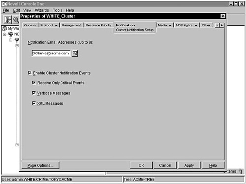
That completes our lesson in the Cluster object. Remember, the Cluster object is the cornerstone of NCS and eDirectory integration. As such, it behaves as both a leaf and container object. Now, let’s explore the next clustering object: the Master IP Address Resource.
The Master IP Address Resource object includes a number of configuration properties related to cluster scripts, failover and failback node settings, and critical cluster policies (see Figure 14.15).

Even though the Master IP Address Resources object behaves just like any other Cluster object in eDirectory, it is special because the master IP address is automatically assigned to the master node. Therefore, many of the properties associated with this object in ConsoleOne (including (Node) Cluster resource load and unload scripts, policies, and Nodes) can only be viewed, but not edited.
You can configure the properties of each Cluster Server Node object by using the Nodes tab within the Properties option of ConsoleOne. Each cluster node has a corresponding object in eDirectory with properties for the server node number, host IP address, and context information for the host NetWare server.
TIP
In addition to Cluster IP Address resources and Server Node objects, the Cluster object contains cluster resource templates. These templates enable you to quickly create resources for a variety of services including DHCP, iFolder, and GroupWise.
That completes step 3: NCS configuration. As you can see, most of your cluster configuration activities focus on the Cluster object itself. After you’ve properly configured this object in eDirectory, you’re well on your way to a highly available network. Now, let’s complete NCS installation with a quick test in step 4.
Before you can let users loose on your new highly available Novell cluster, you must test the new configuration. Fortunately, both ConsoleOne and NetWare Remote Manager provide special status screens for viewing cluster states. In addition, these cluster status views enable you to migrate resources, check the event log, and print (or save) an HTML report.
To display the Cluster State View screen in ConsoleOne, use the Cluster State View option under View (see Figure 14.16). At the top of the view, ConsoleOne displays the Cluster object name and epoch number. The epoch number indicates the number of times that the cluster state has changed since it was created. In addition, an icon for each cluster server is displayed in the middle and all cluster resources are shown in a list at the bottom of the screen. Finally, gauges in the middle enable you to track the percentages of nodes and resources available.

The cluster node and resource icons in the Cluster State View screen display in different colors, depending on their operating state:
![]() Green—When the icons are green, nodes and resources are in normal operating condition.
Green—When the icons are green, nodes and resources are in normal operating condition.
![]() Red—When a node icon is red with a break in the icon, the node has failed. When a resource icon is red, the resource is waiting for administrator intervention.
Red—When a node icon is red with a break in the icon, the node has failed. When a resource icon is red, the resource is waiting for administrator intervention.
![]() Gray—When a node icon is gray with no break, it is not a member of the cluster or its state is unknown.
Gray—When a node icon is gray with no break, it is not a member of the cluster or its state is unknown.
![]() No color (or blank)—When a resource icon is blank or has no color, it is unassigned, offline, changing state, or in the process of loading or unloading.
No color (or blank)—When a resource icon is blank or has no color, it is unassigned, offline, changing state, or in the process of loading or unloading.
![]() Yellow—The master node has a yellow ball in the middle of its icon.
Yellow—The master node has a yellow ball in the middle of its icon.
TIP
You can also test and monitor your new cluster via the Web by using NetWare Remote Manager. To get to the Cluster Status screen, simply click the Cluster Manager link within the Clustering section. The Cluster Status screen within NetWare Remote Manager operates almost identically to the Cluster State View screen in ConsoleOne.
In addition to colored icons, ConsoleOne provides a variety of resource states to help you monitor the health of your cluster resources. As you saw in Figure 14.16, the cluster state is displayed for each resource at the bottom of the view. Table 14.4 provides a detailed description of each state parameter offered in the cluster state view of ConsoleOne.
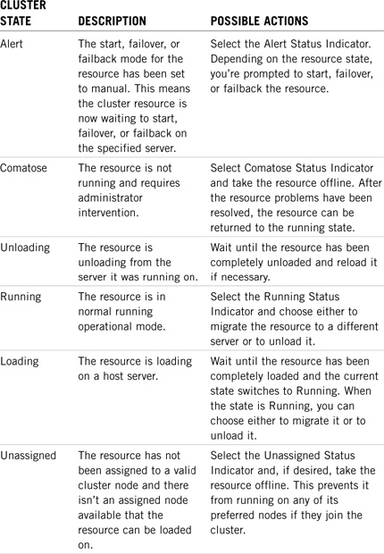
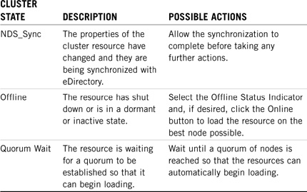
In addition to the Cluster State View in ConsoleOne, you can use event logs and HTML reports to monitor the health of your new cluster. The Event Log tab displays a detailed history of your cluster sorted by time stamp. In addition, you can sort events by node, resource, or cluster event. You can reverse the sort order by pressing the Shift key while selecting a column heading. The event log is stored on the SBD cluster partition on the shared storage device, which ensures that it’s always available.
In addition, you can select the HTML Report tab in ConsoleOne to display a more detailed report of the state of your cluster. You can save both the event log and HTML report to a file for printing or viewing at a later date. NCS 1.6 supports a number of console commands for cluster testing, monitoring, and loading. Table 14.5 provides a detailed list of cluster-related console commands in NetWare 6.
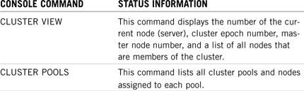
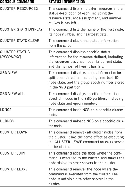
Congratulations! You’ve used NCS 1.6 to build a NetWare 6 high availability solution.
In this lesson, you learned how to install NCS 1.6 on a number of server nodes by using a simple four-step process. First, we built the hardware and software architecture with our eye on minimum hardware, software, and disk system requirements. In step 2, we created a cluster by installing NCS 1.6 on each server and adding a Cluster object to eDirectory.
In step 3, we performed some NCS configuration tasks by using the new eDirectory objects. NCS configuration focused on three important tasks: configuring the Cluster object, configuring the Master IP Address Resource object, and configuring each of the Cluster Server Node objects. Finally, in step 4, we learned how to test and monitor the cluster state by using ConsoleOne, NetWare Remote Manager, and NCS-based console commands.
Now let’s complete our high availability quest for five 9s by learning how to configure two network resource solutions: file access and services.
Test Objectives Covered:
![]() Configure NCS for High Availability File Access
Configure NCS for High Availability File Access
![]() Identify Cluster-Aware and Cluster-Naive Applications
Identify Cluster-Aware and Cluster-Naive Applications
![]() Identify How to Cluster-Enable an Application
Identify How to Cluster-Enable an Application
![]() Identify How to Assign Nodes to a Resource
Identify How to Assign Nodes to a Resource
![]() Identify How to Set Start, Failover, and Failback Modes
Identify How to Set Start, Failover, and Failback Modes
![]() Identify How to View and Edit Load and Unload Scripts
Identify How to View and Edit Load and Unload Scripts
![]() Manage Resources in an NCS Cluster
Manage Resources in an NCS Cluster
![]() Identify How to Find NCS Configuration and Troubleshooting Information
Identify How to Find NCS Configuration and Troubleshooting Information
Now we’re clustering! Well, actually, the servers are clustering—but the users aren’t.
After you’ve created an NCS cluster, you must configure cluster resources to make them highly available to users. There are two main network resources that users are interested in: files and services. In the remaining lesson of this chapter, you’ll learn how to configure high availability for each of these resources:
Let’s continue by enabling an NCS file system.
As you just learned, there are two main network resources that you can make highly available by using NCS: files and services. In this section, we’ll explore using NCS 1.6 to create high availability file access. Fortunately, clustering leverages the sophistication and stability of Novell Storage Services (NSS).
To cluster-enable NSS, you must first create a shared disk partition and NSS file system on the shared device. Then you can cluster-enable the NSS components (such as volumes and pools) by associating them with a new Virtual Server object via a unique IP address. This enables NSS volumes to be accessible even if the user’s host server fails—such is the definition of high availability.
To configure NCS 1.6 to make data and files highly available to users, we must perform three steps:
1. Create a shared disk partition
2. Create a shared NSS volume and pool
3. Cluster-enable the NSS volume and pool
Now, let’s use ConsoleOne to create a NetWare 6 high availability file-access solution.
As you recall from earlier, NetWare 6 NSS architecture relies on partitions, pools, and volumes (in that order) for scalable file storage. Therefore, it makes sense that you need to create a shared disk partition to enable high availability file access. We are effectively building a shared NSS file system on the SAN.
To create a shared disk partition on your clustered SAN, make sure that all of your nodes are attached to the SAN and the appropriate drivers have been loaded. Then activate ConsoleOne and navigate to the Cluster object. Right-click it and select Properties. On the Media tab, select Devices and choose the device that will host your shared partition. Make sure that the Shareable for Clustering box is marked. In fact, this box should be marked because NetWare 6 detects that it is a shared storage device when you add it to the SAN. If this option isn’t chosen, it means that NetWare did not detect the device as a shared storage device. This might be a problem.
On the Media tab, select Partitions and click New. Select the device once again and configure the following parameters:
![]() Partition Size—Specify the largest possible partition size the device will support.
Partition Size—Specify the largest possible partition size the device will support.
![]() Partition Type—NSS is selected by default.
Partition Type—NSS is selected by default.
![]() Hot Fix—Should be marked.
Hot Fix—Should be marked.
![]() Mirror—Should be marked.
Mirror—Should be marked.
![]() Create New Mirror Group—Should be marked.
Create New Mirror Group—Should be marked.
To create the new shared partition, click OK. That completes step 1. In step 2, you must create a shared NSS volume and pool for hosting clustered files.
Storage pools are next in the NSS architecture hierarchy. Although storage pools must be created prior to creating NSS volumes, you can create both at the same time by using the Create a New Logical Volume option in ConsoleOne.
First, right-click any Server object in your cluster and select Properties. Next, choose Media, NSS Logical Volumes, New. The Create a New Logical Volume dialog box should appear. In the Name field, enter a unique name for the volume. ConsoleOne will choose a subsequent related name for the host storage pool. Select Next to continue.
When the Storage Information dialog box appears, select the shared disk partition that you created in step 1. This is where the shared storage pool and volume will reside. Enter a quota for the volume or select the box to allow the volume to grow to the pool size. Remember that we want to make the volume and pool as large as possible because they will host shared file storage. After you’ve selected Next, the Create a New Pool dialog box will appear. Enter a related name for the pool and select OK.
Because the partition you selected is on a shared storage device, the Create a New Pool Cluster dialog box appears with the following options:
![]() Cluster Enable on Creation—(Selected by default.) This option causes the pool to be activated and cluster-enabled when it is created.
Cluster Enable on Creation—(Selected by default.) This option causes the pool to be activated and cluster-enabled when it is created.
![]() Virtual Server Name—A Virtual Server object is created and given the name of the Cluster object plus the cluster-enabled pool when you cluster-enable a pool. The Virtual Server object contains the IP address for the NSS pool and is associated with the pool and volume.
Virtual Server Name—A Virtual Server object is created and given the name of the Cluster object plus the cluster-enabled pool when you cluster-enable a pool. The Virtual Server object contains the IP address for the NSS pool and is associated with the pool and volume.
![]() IP Address—The IP address required by each cluster-enabled NSS pool is used to provide access, migration, and failover capability to the cluster-enabled pool. Regardless of which server in the cluster is accessing the pool, the IP address remains assigned to the pool.
IP Address—The IP address required by each cluster-enabled NSS pool is used to provide access, migration, and failover capability to the cluster-enabled pool. Regardless of which server in the cluster is accessing the pool, the IP address remains assigned to the pool.
![]() Advertising Protocols—Choices for advertising protocols over the network for the NSS pool IP address include NCP (the protocol used by Novell clients), CIFS (the protocol used by Microsoft clients), and AFP (the protocol used by Macintosh clients). When you select any of the protocols, lines are added to the pool resource load and unload scripts to activate the selected protocols on the cluster. This ensures that the cluster-enabled pool you create is highly available to your clients.
Advertising Protocols—Choices for advertising protocols over the network for the NSS pool IP address include NCP (the protocol used by Novell clients), CIFS (the protocol used by Microsoft clients), and AFP (the protocol used by Macintosh clients). When you select any of the protocols, lines are added to the pool resource load and unload scripts to activate the selected protocols on the cluster. This ensures that the cluster-enabled pool you create is highly available to your clients.
Enter an IP address for the NSS pool and make any other changes to the configuration information.
The Attribute Information dialog box will appear next. Review and edit the attributes as necessary. When you’ve finished editing the volume attributes, select Finish to complete step 2.
Now that you’ve created an NSS storage pool and volume on the shared storage device, it’s time to cluster-enable them. Believe it or not, NetWare 6 does not cluster-enable shared volumes by default. At this point, the volume and pool are currently assigned as local resources to the server you chose in step 2. Now we will cluster-enable it in step 3.
When you create a standard NSS volume, it’s associated with a specific server. For example, the WHITE_NSSVOL01 volume would be connected to the WHITE-SRV1 server. The problem with this scenario is that all files on the NSS volume are subject to a single point of failure: the WHITE-SRV1 server. Furthermore, if WHITE-SRV1 goes down, its server IP address is no longer broadcast and the volume cannot be migrated to a new server for high availability.
To solve this problem, NCS enables you to cluster-enable an NSS volume and pool independently of the physical server object. That means you associate the volume and pool with a new virtual server with its own IP address. This enables the volume to be accessible even if WHITE-SRV1 goes down.
During the cluster-enabling process, the old Volume object is replaced with a new Volume object that is associated with the pool and the old Pool object is replaced with a new Pool object that is associated with the virtual server. Table 14.6 provides a detailed description of this eDirectory object transition.
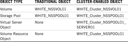
TIP
You should create an A record on your DNS server for the new virtual server’s IP address. This enables your users to log in using the logical DNS name.
The following are five important guidelines that you must follow when you cluster-enable volumes and pools in NCS 1.6:
![]() Cluster-enabled volumes no longer appear as cluster resources. If you want each cluster-enabled volume to be its own cluster resource, you must create a one-to-one mapping from volume to storage pool. Each cluster-enabled NSS pool requires its own IP address for the virtual server. Therefore, it’s important to note that the load and unload scripts in Cluster Resource objects apply to pools directly (not volumes).
Cluster-enabled volumes no longer appear as cluster resources. If you want each cluster-enabled volume to be its own cluster resource, you must create a one-to-one mapping from volume to storage pool. Each cluster-enabled NSS pool requires its own IP address for the virtual server. Therefore, it’s important to note that the load and unload scripts in Cluster Resource objects apply to pools directly (not volumes).
![]() The first volume that you cluster-enable in a pool automatically cluster-enables the entire pool. After the pool has been cluster-enabled, you must cluster-enable all volumes in the pool if you want them to be mounted during a failover. This is because NSS only mounts cluster-enabled volumes when pools are migrated throughout the cluster. Any volumes in the pool that are not cluster-enabled must be mounted manually.
The first volume that you cluster-enable in a pool automatically cluster-enables the entire pool. After the pool has been cluster-enabled, you must cluster-enable all volumes in the pool if you want them to be mounted during a failover. This is because NSS only mounts cluster-enabled volumes when pools are migrated throughout the cluster. Any volumes in the pool that are not cluster-enabled must be mounted manually.
![]() To allow each cluster-enabled volume to be its own cluster resource, each volume must have its own pool.
To allow each cluster-enabled volume to be its own cluster resource, each volume must have its own pool.
![]() If a server application does not require NetWare client access to volumes, cluster-enabling those pools and volumes might not be necessary.
If a server application does not require NetWare client access to volumes, cluster-enabling those pools and volumes might not be necessary.
![]() Storage pools should be deactivated and volumes should be dismounted before being cluster-enabled.
Storage pools should be deactivated and volumes should be dismounted before being cluster-enabled.
To cluster-enable an NSS volume (and pool) using ConsoleOne, navigate to the Cluster object and select File, New, Cluster, and Cluster Volume. Then browse and select a volume on the shared disk system to be cluster-enabled. Next enter an IP address for the new volume. This is required for only the first volume in the pool. Subsequent volumes will adopt the same IP address because it is assigned at the pool level. Finally, mark the following three fields and click Create: Online Resource After Create (to mount the volume after it has been created), Verify IP Address (validates that there are no IP address conflicts), and Define Additional Properties.
REAL WORLD
When you cluster-enable an NSS volume (and pool), two important new objects are created: a Virtual Server object and a Cluster Volume object. During the creation process, ConsoleOne and NetWare Remote Manager give you the option to change the default name of each of these objects. Here is the syntax that NCS normally uses:
![]() The Virtual Server object is given the name of the Cluster object plus the cluster-enabled pool. For example, if the cluster name is WHITE_Cluster and the cluster-enabled pool is NSSPool01, the default virtual server name is WHITE_Cluster_NSSPool01_Server.
The Virtual Server object is given the name of the Cluster object plus the cluster-enabled pool. For example, if the cluster name is WHITE_Cluster and the cluster-enabled pool is NSSPool01, the default virtual server name is WHITE_Cluster_NSSPool01_Server.
![]() The Cluster Volume object is given the name of the Cluster object plus the volume name. For example, if the cluster name is WHITE_Cluster and the volume name is NSSVol01, the default cluster-enabled Volume object name is WHITE_Cluster_NSSVol01.
The Cluster Volume object is given the name of the Cluster object plus the volume name. For example, if the cluster name is WHITE_Cluster and the volume name is NSSVol01, the default cluster-enabled Volume object name is WHITE_Cluster_NSSVol01.
That completes our lesson in NCS high availability file access. In this section, you learned the three-step process for creating a clustered file access solution. First, we created a shared disk partition on the SAN. Then we created an NSS volume and pool to host the shared files. Finally, we cluster-enabled the volume and pool with a new Virtual Server object. This process should help you sleep at night now that your users’ files are always up.
In the next NCS lesson, you’ll learn how to build a high availability service solution.
Network services are just as important to users as files. With NCS, you can make network applications and services highly available to users even if they don’t recognize the cluster. Novell already includes a number of cluster-aware applications that take full advantage of NCS clustering features (one example is GroupWise). However, you can also cluster-enable any application by creating a cluster resource and migrating it into NCS.
In this section, you’ll learn how to use NCS 1.6 to guarantee always-up NetWare 6 services. Along the way, we’ll discover two different types of NCS resources:
![]() Cluster-aware applications are programmed to take advantage of NCS clustering. These applications always know that they are running within an NCS cluster and try very hard to stay available. Table 14.7 lists cluster-aware applications in NCS 1.6.
Cluster-aware applications are programmed to take advantage of NCS clustering. These applications always know that they are running within an NCS cluster and try very hard to stay available. Table 14.7 lists cluster-aware applications in NCS 1.6.
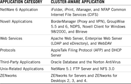
![]() Cluster-naive applications are not programmed to recognize NCS clustering. Fortunately, NCS does support cluster-naive applications; however, failover and failback operations are not as seamless as with their cluster-aware cousins. In this case, NCS must work extra hard to ensure that cluster-naive resources are migrated to other cluster nodes when their host server fails.
Cluster-naive applications are not programmed to recognize NCS clustering. Fortunately, NCS does support cluster-naive applications; however, failover and failback operations are not as seamless as with their cluster-aware cousins. In this case, NCS must work extra hard to ensure that cluster-naive resources are migrated to other cluster nodes when their host server fails.
In this final NCS lesson, you’ll learn how to configure high availability services by performing these five administrative tasks:
![]() Cluster-enabling applications
Cluster-enabling applications
![]() Assigning nodes to a cluster resource
Assigning nodes to a cluster resource
![]() Configuring cluster resource failover
Configuring cluster resource failover
![]() Migrating cluster resources
Migrating cluster resources
![]() Configuring cluster resource scripts
Configuring cluster resource scripts
Cluster resources are at the center of the NCS universe. To cluster-enable any network service, such as an application, you must create a corresponding cluster resource. The resource includes a unique IP address and is available for automatic or manual migration during a node failure.
You can create cluster resources for cluster-aware or cluster-naive applications, including Web sites, email servers, databases, or any other server-based application. This magic is accomplished using ConsoleOne or NetWare Remote Manager. After you’ve created an application’s cluster resource, you can assign nodes to it and configure failover options (we’ll discuss these topics in just a moment).
To create a cluster resource for a given network application, launch ConsoleOne. Next navigate to the host Cluster object and select File, New, Cluster, and Cluster Resource. Then enter a descriptive name for the cluster resource that defines the application it will be serving. Next, mark the Inherit from Template field to perform additional configurations based on a pre-existing template. If a template does not exist, select the Define Additional Properties box to make the configurations manually. Finally, if you want the resource to start on the master node as soon as it has been created, select Online Resource After Create and click Create.
You’ve created a new cluster resource in eDirectory for your highly available application. However, this is only the beginning. For users to have constant access to the application, you must assign nodes to the cluster resource, configure failover options, and build load scripts so that NCS knows how to enable the application. Let’s continue with node assignment.
Before your new cluster resource is highly available, it must have two (or more) nodes assigned to it. Furthermore, the order in which the nodes appear in the Assigned Nodes list determines their priority during failover.
To assign nodes to a cluster resource in ConsoleOne, navigate to the new cluster resource in eDirectory. Next, right-click it and select Properties. When you activate the Nodes tab, two lists will appear: Unassigned (which should have two or more servers in it) and Assigned (which should be blank).
To assign nodes to this cluster resource, simply highlight the server from the Unassigned list and click the right-arrow button to move the selected server to the Assigned Nodes list. When you have two (or more) servers in the Assigned Nodes list, you can use the up-arrow and down-arrow buttons to change the failover priority order.
Speaking of failover, let’s continue with a quick lesson in configuring cluster resource failover.
After you’ve created a cluster resource for your application and added nodes to it, you’re ready to configure the automatic and manual failover settings. The following is a list of the failover modes supported by the Policies page in ConsoleOne:
![]() Start mode—NCS supports two start modes for cluster resource: Automatic and Manual. When set to Automatic, the cluster resource automatically starts on its preferred node anytime the cluster is activated. When set to Manual, the cluster resource goes into an Alert state any time the cluster is restarted. In this state, ConsoleOne displays the resource as an alert and presents you with the option of manually starting the resource. The default mode is Automatic.
Start mode—NCS supports two start modes for cluster resource: Automatic and Manual. When set to Automatic, the cluster resource automatically starts on its preferred node anytime the cluster is activated. When set to Manual, the cluster resource goes into an Alert state any time the cluster is restarted. In this state, ConsoleOne displays the resource as an alert and presents you with the option of manually starting the resource. The default mode is Automatic.
![]() Failover mode—NCS also supports two failover modes for cluster resources: Automatic and Manual. When set to Automatic, the cluster resource starts on the next server on the Assigned Nodes list when its host node fails. When set to Manual, the cluster resource goes into an alert state when its host node fails. In the Alert state, ConsoleOne enables you to manually move the resource to any cluster node of your choice. The default mode is Automatic.
Failover mode—NCS also supports two failover modes for cluster resources: Automatic and Manual. When set to Automatic, the cluster resource starts on the next server on the Assigned Nodes list when its host node fails. When set to Manual, the cluster resource goes into an alert state when its host node fails. In the Alert state, ConsoleOne enables you to manually move the resource to any cluster node of your choice. The default mode is Automatic.
![]() Failback mode—NCS supports three failback modes for cluster resources: Automatic, Manual, and Disable. When set to Automatic, the cluster resource automatically fails back to its most preferred node when that node rejoins the cluster. When set to Manual, the cluster resource goes into an alert state when its preferred node rejoins the cluster. At this point, ConsoleOne enables you to move the resource back to its preferred node when you think the time is right. In Disable mode, the cluster resource doesn’t do anything when its most preferred node rejoins the cluster. This is the default setting and is recommended under most circumstances.
Failback mode—NCS supports three failback modes for cluster resources: Automatic, Manual, and Disable. When set to Automatic, the cluster resource automatically fails back to its most preferred node when that node rejoins the cluster. When set to Manual, the cluster resource goes into an alert state when its preferred node rejoins the cluster. At this point, ConsoleOne enables you to move the resource back to its preferred node when you think the time is right. In Disable mode, the cluster resource doesn’t do anything when its most preferred node rejoins the cluster. This is the default setting and is recommended under most circumstances.
If you don’t feel comfortable automatically migrating cluster resources in NCS, you can always migrate them manually. Let’s continue with a quick lesson in resource migration.
TIP
When configuring cluster resource failover modes, ConsoleOne presents an Ignore Quorum check box. By selecting this parameter, you can instruct NCS to ignore the clusterwide timeout period and node number limits. This ensures that the cluster resource will be launched immediately on any server in the Assigned Nodes list as soon as the server is brought online. I highly recommend that you check the Ignore Quorum box because time is of the essence when building a high-availability solution.
You can migrate cluster resources to different nodes in the Assigned Nodes list without waiting for a failure to occur. This type of load balancing is a very good idea to lessen the performance load on any specific server. In addition, resource migration is a great tool to free up servers when they’re scheduled for routine maintenance. Finally, migration enables you to match resource-intensive applications with the best server hardware.
To migrate cluster resources by using ConsoleOne, navigate to the Cluster object that contains the resource that you want to migrate. Highlight the Cluster object and select View, Cluster State View. In the Cluster Resource list, select the resource you want to migrate.
The Cluster Resource Manager screen appears and displays the resources host server and a list of possible servers that you can migrate the resource to. Select a server from the list and click the Migrate button to manually move the resource to the new server. Furthermore, you can select a resource and click the Offline button to unload it from its host server. At this point, the resource hangs in limbo until you manually assign it to another node.
So far, you’ve created a cluster resource for your network application and assigned nodes to it. Then you configured automatic cluster failover modes and migrated resources manually for load balancing. That leaves us with only one important high availability task: configuring cluster resource scripts. This is probably the most important task because it determines what the resources do when they’re activated.
Ready, set, script!
When a cluster resource loads, NCS looks to the load script to determine what to do. This is where the application commands and parameters are stored for the specific cluster resource. Load scripts are analogous to NCF (NetWare configuration files) batch files that run automatically when NetWare servers start. In fact, cluster resource load scripts support any command that you can place in an NCF file.
Similarly, the unload script contains all the commands necessary to deactivate the cluster resource or take it offline. Both load and unload scripts can be viewed or edited by using ConsoleOne or NetWare Remote Manager.
To configure a specific cluster resource’s load script in ConsoleOne, navigate to the Cluster Resource object and right-click it. Next, select Properties and enable the Load Script tab. The Cluster Resource Load Script window will appear. Simply edit the commands as you would any NCF batch file. In addition, you’ll have to define a timeout setting for the load script. If the load script does not complete within the timeout period (600 seconds by default), the resource will go into a comatose state.
To help you troubleshoot configuring and running a two-node NCS cluster, Novell makes NCS documentation and technical information documents (TIDs) available at its Web site. To access NCS documentation, consult www.novell.com/documentation/lg/ncs6/index.html.
To access NCS clustering TIDs, access the Novell Web site (www.novell.com) and then select Support, Knowledgebase. For the product category, select NetWare and then select the TIDs product set. Enter cluster for the search term and the select Search Now.
In this NetWare 6 lesson, you learned how to implement Novell’s new AAA—Anytime, Anywhere, Always Up. Always up is accomplished by using NCS (Novell Cluster Services). You also learned how to design a NetWare 6 NCS solution, how to install it, how to configure it, and how to keep it running.
In the first NCS section, we explored high availability in theory and built an impressive NCS vocabulary, including mean time between failures (MTBF) and mean time to recovery (MTTR). After we nailed down the basic fundamentals of NCS, we used NCS 1.6 to design a clustering solution. In the basic system architecture, we learned how to use a Fiber Channel or SCSI configuration to share a central disk system.
In the third lesson, we discovered the four-step process for installing NCS 1.6. Then, we learned how to configure two high availability solutions: file access and services. At the end of the chapter, we learned how to manage resources in an NCS cluster, and where to find help through the Novell Web site. So, there you go...Novell Cluster Services in all its glory!!
Next up, Chapter 15, “Novell Troubleshooting Tools,” provides us with the all-important troubleshooting toolset—a must have for any qualified CNE.
Ready, set, let’s troubleshoot!