
Chapter 19 Novell eDirectory Tree Design
This chapter covers the following testing objectives for Novell Course 575: Novell eDirectory Design and Implementation:
![]() Create an eDirectory Naming Standards Document
Create an eDirectory Naming Standards Document
![]() Design the Upper Layers of the eDirectory Tree
Design the Upper Layers of the eDirectory Tree
![]() Design the Lower Layers of the eDirectory Tree
Design the Lower Layers of the eDirectory Tree
![]() Identify Fundamental Directory Design Factors
Identify Fundamental Directory Design Factors
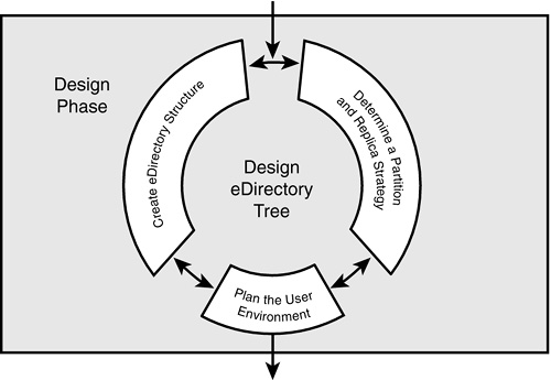
eDirectory design is the most critical phase of the NetWare design and implementation process. It affects virtually every network user and/or resource. As you can see in Figure 19.1, the eDirectory design phase consists of five interrelated tasks:
![]() eDirectory naming standards—A complete naming standards document is important because it enables you to design an eDirectory database that’s flexible, easy to use, and meets your business needs.
eDirectory naming standards—A complete naming standards document is important because it enables you to design an eDirectory database that’s flexible, easy to use, and meets your business needs.
![]() eDirectory tree design—Next you should convert your design input into a preliminary design of your eDirectory tree. The top layers should be based on location and the bottom layers should be based on function. The design of the container structure should resemble the shape of a pyramid, with most of the containers at the bottom and fewer containers at the top.
eDirectory tree design—Next you should convert your design input into a preliminary design of your eDirectory tree. The top layers should be based on location and the bottom layers should be based on function. The design of the container structure should resemble the shape of a pyramid, with most of the containers at the bottom and fewer containers at the top.
![]() Partition and replica design—When the tree design is in place, you need to divide the new tree into smaller pieces (that is, partition it) and strategically place copies of the pieces on particular servers in the network (replica placement). This task is important because it directly affects your network’s performance, accessibility, and fault tolerance. (Note: This task was covered in Chapter 17, “Novell eDirectory Troubleshooting.”)
Partition and replica design—When the tree design is in place, you need to divide the new tree into smaller pieces (that is, partition it) and strategically place copies of the pieces on particular servers in the network (replica placement). This task is important because it directly affects your network’s performance, accessibility, and fault tolerance. (Note: This task was covered in Chapter 17, “Novell eDirectory Troubleshooting.”)
![]() Time synchronization design—Next you must build a time synchronization system that ensures consistent time stamps throughout the network. You can choose to accept the NetWare 6 defaults or you can institute a customized time synchronization strategy; for instance, one that mixes IPX and IP protocol segments. (Note: This task was covered in Chapter 5, “NetWare 6 eDirectory Management.”)
Time synchronization design—Next you must build a time synchronization system that ensures consistent time stamps throughout the network. You can choose to accept the NetWare 6 defaults or you can institute a customized time synchronization strategy; for instance, one that mixes IPX and IP protocol segments. (Note: This task was covered in Chapter 5, “NetWare 6 eDirectory Management.”)
![]() eDirectory accessibility design—Finally, you should create a user environment plan that addresses special eDirectory accessibility considerations, including mobile users, remote users, login scripts, bindery services, connections, and non-DOS workstations. (Note: This task will be covered in Chapter 20, “Novell eDirectory Accessibility Design.”)
eDirectory accessibility design—Finally, you should create a user environment plan that addresses special eDirectory accessibility considerations, including mobile users, remote users, login scripts, bindery services, connections, and non-DOS workstations. (Note: This task will be covered in Chapter 20, “Novell eDirectory Accessibility Design.”)
So much to learn, and so little time. Let’s start with a closer look at the fundamentals of object naming, and explore a naming standards document for ACME.
Test Objective Covered:
![]() Create an eDirectory Naming Standards Document
Create an eDirectory Naming Standards Document
The eDirectory design phase begins with an eDirectory naming standards document. This document provides guidelines for naming key container and leaf objects (including Users, Printers, Servers, Volumes, Print Queues, and Organizational Units). In addition, it identifies standard properties and value formats.
eDirectory uses a mechanism called the schema to define the eDirectory naming structure for all network resources. The schema is distributed to all eDirectory servers and follows specific rules. Unlike the NetWare 3 bindery, eDirectory is a special-purpose naming service that stores objects in a hierarchical format and services up to billions of objects per server (assuming eDirectory Version 8 and higher). Your understanding of the schema will help you manage the internal structure of eDirectory naming. It will also help you plan for the future through supplemental object types, add-on products, and third-party applications.
Let’s start our discussion of eDirectory naming standards with a brief overview of eDirectory object types. Then we’ll explore eDirectory naming rules, including distinguished names, relative distinguished names, context, typeful, and finally, typeless naming.
The directory consists of the schema, objects, properties, and values.
The schema defines the types of objects that you can create, as well as what information is required when the object is created. Each type of object has associated with it a defined schema class. NetWare 6 ships with the base schema that, when modified, becomes known as an extended schema. Modifications to the schema are usually done with the Schema Manager in the ConsoleOne utility.
An object is similar to a record or row of information in a database table. It contains information about a particular network entity. eDirectory represents each network resource as an object in the directory. For example, a User object represents a particular user on the network. An object can be a physical resource (such as a workstation), an eDirectory resource (such as a group), or an organizational resource (such as a container).
An object property is similar to a field in a database record. It is a category of information you can store about an object. For example, properties of a User object include such things as login name, password, and telephone number. Each type of object has a specific set of properties associated with it; this defines its class. Properties are predefined by eDirectory and determine how a given object can be used. For example, server properties differ from printer properties because they are different eDirectory objects with different functions.
Three important types of eDirectory properties include the following:
![]() Required properties—These properties contain vital object data and therefore must be supplied to create the object. Required properties can’t be deleted. For example, when you create a User object, you must indicate values for the Login Name and Last Name properties. As a matter of fact, the name of an object is always a required property. (Otherwise, you would have no way of referring to it.) In contrast, the required properties for a non-NDPS Printer object include Printer Name, Network Address, and Configuration Information.
Required properties—These properties contain vital object data and therefore must be supplied to create the object. Required properties can’t be deleted. For example, when you create a User object, you must indicate values for the Login Name and Last Name properties. As a matter of fact, the name of an object is always a required property. (Otherwise, you would have no way of referring to it.) In contrast, the required properties for a non-NDPS Printer object include Printer Name, Network Address, and Configuration Information.
![]() Multivalued properties—These properties support more than one entry. For example, the Telephone Number property associated with a User object can hold multiple phone numbers for that user. Other User-related multivalued properties include Title, Location, and Fax Number. (This type of multivalued property is represented in ConsoleOne with a “...” button to the right of the property field. If you click this button, you’ll be allowed to enter additional entries for the property.)
Multivalued properties—These properties support more than one entry. For example, the Telephone Number property associated with a User object can hold multiple phone numbers for that user. Other User-related multivalued properties include Title, Location, and Fax Number. (This type of multivalued property is represented in ConsoleOne with a “...” button to the right of the property field. If you click this button, you’ll be allowed to enter additional entries for the property.)
![]() Optional properties—These properties contain nonvital information about an object. As such, you need to supply values for them only if you want to do so. Examples include a user’s title, telephone number, and fax number.
Optional properties—These properties contain nonvital information about an object. As such, you need to supply values for them only if you want to do so. Examples include a user’s title, telephone number, and fax number.
Finally, a property value is similar to a data string in a field of a database record. In other words, it’s a data item associated with a property. For example, the value associated with the Password property of a User object would be the actual password for that User object.
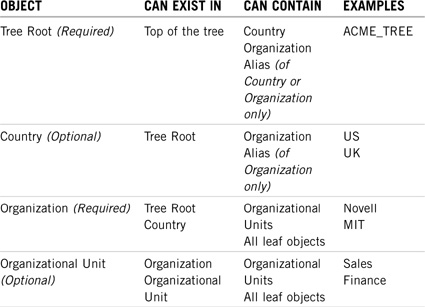
Examine Table 19.1 for an illustration of the relationship between eDirectory objects, properties, and values.

As we discussed earlier, the directory is an object-oriented database that’s organized in a hierarchical structure called the eDirectory tree. It provides a way to view the logical organization of network resources stored in the directory database. As you can see in Figure 19.2, the tree is similar to a file system.

The schema contains object classes that represent the actual definition of each type of eDirectory object. eDirectory contains the following three main classes of objects:
![]() Tree root
Tree root
![]() Container objects
Container objects
![]() Leaf objects
Leaf objects
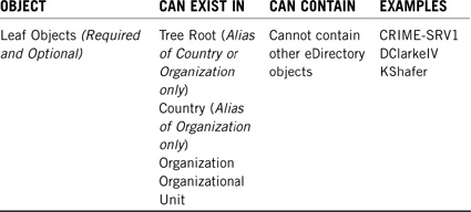
The top of the tree is called the Tree Root. Container objects, which are analogous to folders, define the organizational boundaries of the directory and are used to store other container objects and/or leaf objects, depending on which type of container they are. (A container object is called a parent object if it contains other objects.) Leaf objects, which are analogous to files, are typically stored in container objects. They’re the physical or logical network resources that provide technical services and WAN functionality. Leaf objects define the lowest level of the eDirectory structure and, thus, cannot contain other objects.
The main difference between eDirectory and DOS architecture is that eDirectory containers have restrictions on where they can be placed and what can be placed in them. Typically, each NetWare 6 network will have only one eDirectory tree. If a network has more than one tree, each will function as a separate, independent database. In other words, resources cannot be shared between them.
In the directory, each network resource is defined as a logical object. There are a number of different types of objects. For example, an object can represent a person (such as a user), a physical resource (such as a printer), an eDirectory resource (such as a group), or an organizational resource (such as an Organizational Unit container).
The bottom line is this: Users don’t access physical resources anymore. Instead, they access logical objects in the eDirectory tree. That means they don’t need to know which NetWare 6 server provides a particular resource. All they need to know is where the resource exists in the logical eDirectory world.
Now that you’ve mastered the subtle differences between eDirectory schema, objects, properties, and values, let’s explore some of the most interesting objects in detail, starting at the top with the Tree Root.
The Tree Root is a required object that defines the top of the eDirectory organizational structure. Because it represents the opening porthole to our eDirectory world, its icon is appropriately a picture of a tree. Each Directory tree can have only one Tree Root, which is created during installation of the first server in that tree. The only objects that can be created directly under the Tree Root are Country, Organization, Domain, Security, Audit File Object, DNS Server, DNS Zone, and Alias (in this case, the Alias object can only point to a Country or Organization object.)
Although some people think of the Tree Root as a container object because it contains all the objects in the Directory, it differs from other container objects in the following ways:
![]() It cannot be created except during installation of the first NetWare 6 server on a network.
It cannot be created except during installation of the first NetWare 6 server on a network.
![]() It is essentially a placeholder; it has only one property: Name. The Tree Root name is shown in the hierarchy of ConsoleOne.
It is essentially a placeholder; it has only one property: Name. The Tree Root name is shown in the hierarchy of ConsoleOne.
![]() It cannot be moved, deleted, or renamed.
It cannot be moved, deleted, or renamed.
![]() It uses the eDirectory tree name, which can be changed at a later date.
It uses the eDirectory tree name, which can be changed at a later date.
Although you can change the eDirectory name of the tree after you’ve created your eDirectory structure, doing so introduces more work for you as the network administrator. For example, when you change the name of the tree, you must also do the following:
![]() Reconfigure clients to use the new name
Reconfigure clients to use the new name
![]() Inform all employees that they must now log in to a different tree name
Inform all employees that they must now log in to a different tree name
![]() Reinstall any applications or utilities that might be affected by the change
Reinstall any applications or utilities that might be affected by the change
![]() Regenerate public and private keys
Regenerate public and private keys
By setting a tree-naming standard at the outset of the creation of your tree, and by deciding on a good name and sticking with it, you can avoid all the extra work.
Like other objects, the Tree Root can be assigned as a trustee of other objects, and other objects can be granted trustee access rights to it. For example, an object can be granted trustee rights to the entire eDirectory tree by making the object a trustee of the Tree Root object (see CNA Study Guide for NetWare 6, for further information on trustee rights.)
Container objects are logical objects that organize (store) other container or leaf objects. A container can represent a country, location within a country, company, department, responsibility center, workgroup, or collection of shared resources. Each class of container object has different rules that define what it can contain and where it can be located in the tree. Each class also has different properties. The following are the most common types of NetWare 6 container objects:
![]() Country—Designates the country where certain parts of the organization reside.
Country—Designates the country where certain parts of the organization reside.
![]() Organization—Represents a company, university, or department. eDirectory supports only one layer of Organization objects; hence, the term one-dimensional. Organizations can hold Organizational Unit containers or Leaf objects.
Organization—Represents a company, university, or department. eDirectory supports only one layer of Organization objects; hence, the term one-dimensional. Organizations can hold Organizational Unit containers or Leaf objects.
![]() Organizational Unit—Represents a division, business unit, or project team within the organization. Organizational Units hold other Organizational Units or leaf objects. They are multidimensional.
Organizational Unit—Represents a division, business unit, or project team within the organization. Organizational Units hold other Organizational Units or leaf objects. They are multidimensional.
Refer to Figure 19.2 earlier in this chapter for an illustration of the relationship between the Tree Root and container objects. The ACME Organization houses other Organizational Units (including LABS) that in turn house leaf objects (such as AEinstein). Let’s take a closer look at these three different container objects.
The Country object is an optional container that organizes a directory tree by country. This type of object can only be defined directly under the Tree Root and must be named using a two-character abbreviation. Novell states that you must use a valid two-character country abbreviation. Presumably, this is to ensure that your network is in compliance with the two-character abbreviations defined in the ISO X.500 standard.
Interestingly, if you create a Country object using the ConsoleOne utility, it allows you to use any two-character name. To determine which two-character names are compliant with the ISO X.500 standard, click Help when creating the Country object and NetWare 6 will tell you whether the name is compliant. You can also visit the ISO Web site at www.iso.ch/iso/en/prods-services/iso3166ma/02iso-3166-code-lists/list-en1.html to see a list of country codes. The only objects that can exist in a Country container are an Organization or Alias object pointing to an Organization.
If you don’t use a Country object, the next layer in the tree is typically an Organization. You can use an Organization object to designate a company, a division of a company, a university or college with various departments, and so on. Every directory tree must contain at least one Organization object. Therefore, it is required. Many small implementations use only the Organization object and place all their resources directly underneath it. Organization objects must be placed directly below the Tree Root unless a Country object is used. Finally, Organization objects can contain all objects except Tree Root, Country, and Organization.
Although most organizations use only one Organization container object because they want to represent all resources in the same organization, you can create more than one Organization container object. Creating one Organization container object is not a strict rule in eDirectory. Creating one Organization container object does represent the fewest disadvantages, however. Some of the conditions under which you might consider more than one Organization container object include the following:
![]() If your organization consists of many companies that do not share the same network
If your organization consists of many companies that do not share the same network
![]() If your organization needs to represent separate business units
If your organization needs to represent separate business units
![]() If your organization has internal guidelines dictating that units within it must remain separate
If your organization has internal guidelines dictating that units within it must remain separate
Earlier, we defined the Organization as a one-dimensional object. That means the tree can support only one layer of Organization objects. If you look closer at the icon, you’ll see a box with multiple horizontal boxes underneath. Additional vertical hierarchy is defined by Organizational Units, which are multidimensional. I’ll describe them in just a moment.
Figure 19.3 illustrates the object dialog box for the ACME Organization using ConsoleOne. Within the screen there are many page buttons that identify categories of eDirectory properties for this object. Associated with each page button is an input screen for a specific set of information. The Identification page button (shown here) enables you to define a variety of Organization properties, including Name, Other Name, Description, Location, Telephone, and Fax Number.
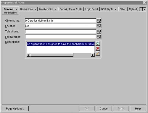
Similar page buttons enable you to configure important Organization parameters, including postal information, print job configurations, trustee assignments, and so on. As far as ACME is concerned, the Organization container defines the top of the functional tree.
The Organizational Unit object is a natural group. It allows you to organize users with the leaf objects they use. You can create a user template for security, group login scripts, trustee assignments, security equivalences, and distributed administrators.
An Organizational Unit can represent a division, business unit, project team, or department. Organizational Units are multidimensional in that you can have many hierarchical levels of containers within containers. Remember, Organization objects can exist at only one level in the eDirectory tree.
Organizational Units are the most flexible containers because they can contain other Organizational Unit objects or leaf objects. As a matter of fact, Organizational Units can contain most of the eDirectory object types, except the Tree Root, Country, or Organization containers (or aliases of any of these).
Now let’s take a look at the real stars of our eDirectory world—leaf objects.
Leaf objects represent logical or physical network resources. Because leaf objects reside at the end of the structural eDirectory tree, they cannot be used to store other objects. In other words, they represent the legendary “end of the road.” As you learned earlier, each class of leaf object has certain properties associated with it. This collection of properties differentiates the various leaf object classes from each other. For example, User objects contain different properties than Printer objects.
The following are some of the key leaf objects covered in this course:
![]() Alias—An Alias object points to another object that exists in a different location in the eDirectory tree. It enables a user to access an object outside of the user’s normal working context (that is, container). An Alias object does not carry trustee rights.
Alias—An Alias object points to another object that exists in a different location in the eDirectory tree. It enables a user to access an object outside of the user’s normal working context (that is, container). An Alias object does not carry trustee rights.
![]() Application—An Application object enables network administrators to manage applications as objects in the eDirectory tree. The advantage of this object is that users don’t have to worry about drive mappings, paths, or rights when they want to execute an application. This information is defined by Application object properties.
Application—An Application object enables network administrators to manage applications as objects in the eDirectory tree. The advantage of this object is that users don’t have to worry about drive mappings, paths, or rights when they want to execute an application. This information is defined by Application object properties.
![]() Directory Map—A Directory Map object represents a logical pointer to a physical directory or folder in the NetWare 6 file system. This object is useful in mapping statements because it enables you to map a drive to a resource without knowing its physical location. If the path to the resource changes, you need only change the path designated in the Directory Map object, rather than any of the login script mapping statements that refer to it.
Directory Map—A Directory Map object represents a logical pointer to a physical directory or folder in the NetWare 6 file system. This object is useful in mapping statements because it enables you to map a drive to a resource without knowing its physical location. If the path to the resource changes, you need only change the path designated in the Directory Map object, rather than any of the login script mapping statements that refer to it.
![]() Group—A Group object defines a list of users for the purpose of assigning access rights or other configuration parameters. The members of a group can be a subset of users in the same container or spread across multiple containers. The difference between containers and groups is that container objects store User objects, whereas Group objects store a list of User objects. Groups enable one of the great CNE tricks: They enable you to specify login script commands to a subset of users with the IF MEMBER OF syntax.
Group—A Group object defines a list of users for the purpose of assigning access rights or other configuration parameters. The members of a group can be a subset of users in the same container or spread across multiple containers. The difference between containers and groups is that container objects store User objects, whereas Group objects store a list of User objects. Groups enable one of the great CNE tricks: They enable you to specify login script commands to a subset of users with the IF MEMBER OF syntax.
![]() LDAP Group—An LDAP Group object stores configuration data (class mappings, attribute mappings, and security policies) for groups of LDAP servers. During installation, an LDAP Group object named LDAP Group <servername> is created by default in the host server’s home container.
LDAP Group—An LDAP Group object stores configuration data (class mappings, attribute mappings, and security policies) for groups of LDAP servers. During installation, an LDAP Group object named LDAP Group <servername> is created by default in the host server’s home container.
![]() LDAP Server—An LDAP Server object stores configuration data for a NetWare 6 server running LDAP Services for eDirectory. During installation, an LDAP Server object named LDAP Server- <servername> is created by default in the host server’s home container. Make sure not to assign the same LDAP Server object to more than one server running LDAP Services for eDirectory.
LDAP Server—An LDAP Server object stores configuration data for a NetWare 6 server running LDAP Services for eDirectory. During installation, an LDAP Server object named LDAP Server- <servername> is created by default in the host server’s home container. Make sure not to assign the same LDAP Server object to more than one server running LDAP Services for eDirectory.
![]() License Certificate—A License Certificate object is used by NetWare Licensing Services (NLS) to monitor and control the use of licensed applications on the network. When the NLS-aware application is installed, a License Certificate object is added to the Licensed Product container.
License Certificate—A License Certificate object is used by NetWare Licensing Services (NLS) to monitor and control the use of licensed applications on the network. When the NLS-aware application is installed, a License Certificate object is added to the Licensed Product container.
![]() NDPS Broker—An NDPS Broker provides three network support services for network printing: Service Registry Services (SRS), Event Notification Services (ENS), and Resource Management Services (RMS). When Novell Distributed Print Services (NDPS) is installed, the installation utility ensures that a Broker object is loaded on your network.
NDPS Broker—An NDPS Broker provides three network support services for network printing: Service Registry Services (SRS), Event Notification Services (ENS), and Resource Management Services (RMS). When Novell Distributed Print Services (NDPS) is installed, the installation utility ensures that a Broker object is loaded on your network.
![]() NDPS Manager—The NDPS Manager is a logical entity used to create and manage NDPS printers and printer agents. The NDPS Manager object stores information used by NDPSM.NLM on a single server. This single server can control multiple printer agents.
NDPS Manager—The NDPS Manager is a logical entity used to create and manage NDPS printers and printer agents. The NDPS Manager object stores information used by NDPSM.NLM on a single server. This single server can control multiple printer agents.
![]() NDPS Printer—NDPS printers magically transform electronic bits into written words. These objects are created by iManager as controlled access printers.
NDPS Printer—NDPS printers magically transform electronic bits into written words. These objects are created by iManager as controlled access printers.
![]() Organizational Role—An Organizational Role object defines a position or role within the organization that can be filled by any designated user. The Organizational Role is particularly useful for rotating positions that support multiple employees, where the responsibilities of the job, and the network access required, are static. If a User object is assigned as an occupant of an Organizational Role, the user absorbs all trustee rights assigned to it. Some Organizational Role examples include PostMaster, Network Administrator, Silicon Valley CEO, and Receptionist.
Organizational Role—An Organizational Role object defines a position or role within the organization that can be filled by any designated user. The Organizational Role is particularly useful for rotating positions that support multiple employees, where the responsibilities of the job, and the network access required, are static. If a User object is assigned as an occupant of an Organizational Role, the user absorbs all trustee rights assigned to it. Some Organizational Role examples include PostMaster, Network Administrator, Silicon Valley CEO, and Receptionist.
![]() Print Server (Non NDPS)—A Print Server (Non NDPS) object represents a network print server used for monitoring queue-based print queues and printers.
Print Server (Non NDPS)—A Print Server (Non NDPS) object represents a network print server used for monitoring queue-based print queues and printers.
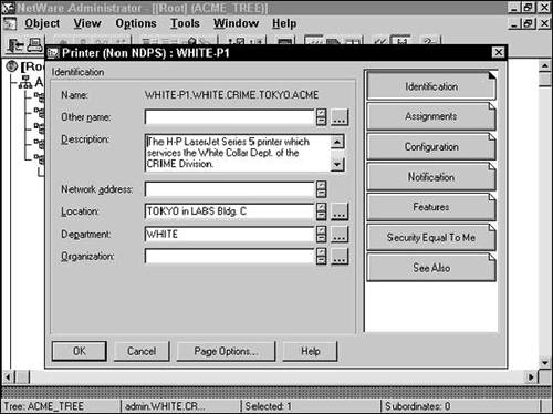
![]() Printer (Non NDPS)—A Printer (Non NDPS) object represents a queue-based physical printing device on the network, such as a printer or plotter. See Figure 19.4 for an illustration of the Printer (Non NDPS) properties that can be managed using ConsoleOne.
Printer (Non NDPS)—A Printer (Non NDPS) object represents a queue-based physical printing device on the network, such as a printer or plotter. See Figure 19.4 for an illustration of the Printer (Non NDPS) properties that can be managed using ConsoleOne.
![]() Profile—A Profile object defines a login script for a subset of users in the same container or spread across multiple containers. (If all the users in a container need the same login script, you should use a Container login script instead.)
Profile—A Profile object defines a login script for a subset of users in the same container or spread across multiple containers. (If all the users in a container need the same login script, you should use a Container login script instead.)
![]() Server—A Server object represents a server running eDirectory on your network. eDirectory supports the following operating system platforms: NetWare, Solaris, Linux, and Windows 2000. You can even create a Server object for bindery servers running NetWare 2 or NetWare 3. This object is used by various leaf objects (such as Volume objects) to identify a physical server that provides particular network services. See Figure 19.5 for an illustration of the Server properties that can be managed using ConsoleOne.
Server—A Server object represents a server running eDirectory on your network. eDirectory supports the following operating system platforms: NetWare, Solaris, Linux, and Windows 2000. You can even create a Server object for bindery servers running NetWare 2 or NetWare 3. This object is used by various leaf objects (such as Volume objects) to identify a physical server that provides particular network services. See Figure 19.5 for an illustration of the Server properties that can be managed using ConsoleOne.

![]() Unknown—An Unknown object represents an eDirectory object that has been corrupted, invalidated, or that cannot be identified as belonging to any of the other leaf classes. For example, an Alias object becomes Unknown when its host is deleted. Ouch!!!
Unknown—An Unknown object represents an eDirectory object that has been corrupted, invalidated, or that cannot be identified as belonging to any of the other leaf classes. For example, an Alias object becomes Unknown when its host is deleted. Ouch!!!
![]() User—A User object represents a person who uses the network (for example, you, me, or Fred). For security reasons, you should create a separate User object for each user on the network. A User object contains a plethora of interesting properties, including Login Name, Password, Full Name, Login Restrictions, and so on. See Figure 19.6 for an illustration of the User properties that can be managed using NetWare Administrator and ConsoleOne.
User—A User object represents a person who uses the network (for example, you, me, or Fred). For security reasons, you should create a separate User object for each user on the network. A User object contains a plethora of interesting properties, including Login Name, Password, Full Name, Login Restrictions, and so on. See Figure 19.6 for an illustration of the User properties that can be managed using NetWare Administrator and ConsoleOne.

![]() Volume—A Volume object represents a physical volume on the network. Volumes are typically created during the server installation process. Remember that a Volume object is a leaf object rather than a container object—even though the ConsoleOne utility might give you the opposite impression. It stores information about a volume including server name, physical volume mapping, and volume use statistics. No information about files and folders on a volume is contained in a Volume object. However, you can access that information through ConsoleOne. Volume objects are supported only on NetWare. If you’re using Unix file system partitions, they cannot be managed using Volume objects.
Volume—A Volume object represents a physical volume on the network. Volumes are typically created during the server installation process. Remember that a Volume object is a leaf object rather than a container object—even though the ConsoleOne utility might give you the opposite impression. It stores information about a volume including server name, physical volume mapping, and volume use statistics. No information about files and folders on a volume is contained in a Volume object. However, you can access that information through ConsoleOne. Volume objects are supported only on NetWare. If you’re using Unix file system partitions, they cannot be managed using Volume objects.
![]() Workstation—A Workstation object enables you to manage network workstations through eDirectory. This leaf object is automatically created when a workstation is registered and imported into the eDirectory tree.
Workstation—A Workstation object enables you to manage network workstations through eDirectory. This leaf object is automatically created when a workstation is registered and imported into the eDirectory tree.
Table 19.2 summarizes some important eDirectory object characteristics.
This completes our discussion of the most interesting eDirectory objects offered by NetWare 6. You’ll want to get to know all these leaf objects because future discussions center around how to organize, design, and manage them. When you understand the relationships between eDirectory objects, you can start building your tree.
TIP
Every leaf object and container object is represented by an icon graphic that depicts its purpose. For example, printers are printers, servers are computers, and users are people. These icons are used throughout this book and in graphical eDirectory utilities. ConsoleOne, for example, uses icons to provide a snapshot of an entire eDirectory tree in a hierarchical structure. This feature makes it easier for administrators and users to locate and use NetWare 6 resources. Cool.
How do you feel? So far, we’ve explored all the physical and logical objects that make up NetWare 6’s revolutionary eDirectory tree. However, this is only the beginning. Your success as a CNE is defined by your ability to manage eDirectory objects and their properties.
Write C for container or L for leaf next to each of the following objects:
1. ___Volume
2. ___Country
3. ___User
4. ___Group
5. ___Organizational Unit
6. ___NetWare Server
7. ___Print Queue
8. ___Organizational Role
9. ___Computer
10. ___Organization
Indicate whether you think each of the following items would be a container or a leaf object. If you think it would be a container object, indicate what type of container (that is, Country, Organization, or Organizational Unit).
1. ________The Human Resources department
2. ________David IV
3. ________A database server
4. ________The PAYCHECK print queue
5. ________ACME, Inc.
6. ________The Administrator Organizational Role
7. ________UK (that is, United Kingdom)
8. ________A dot matrix printer
10. ________The SYS: volume
Test Objective Covered:
![]() Create an eDirectory Naming Standards Document (continued)
Create an eDirectory Naming Standards Document (continued)
Now that you understand what the eDirectory tree is made of, we need to explore how it works. As you manage the eDirectory tree, pay particular attention to its structure. A well-designed tree will make resource access and management much easier.
The structure of the eDirectory tree is both organizational and functional. The location of an object in the tree can affect how users access it and how network administrators manage it. The eDirectory tree structure impacts the following areas of administrative responsibility:
![]() eDirectory planning
eDirectory planning
![]() Resource access
Resource access
![]() Resource setup
Resource setup
You complete these tasks by implementing eDirectory planning guidelines, using proper eDirectory naming structure, and understanding current context.
An efficient eDirectory Directory tree provides all the following benefits:
![]() It makes resource access easier for users.
It makes resource access easier for users.
![]() It makes administration easier for network administrators.
It makes administration easier for network administrators.
![]() It provides fault tolerance for the eDirectory database.
It provides fault tolerance for the eDirectory database.
![]() It decreases network traffic.
It decreases network traffic.
The structure of the tree can be based on location, organization, or administration. In many cases, it’s a combination of all three. Many factors influence the structure of your eDirectory tree. Before you design your tree, you might need to study workgroups, resource allocation, and/or learn how data flows throughout your network.
As a CNE, it’s your responsibility to know how to navigate, manage, design, and troubleshoot the tree. Let’s get started.
eDirectory naming defines rules for locating leaf objects. One of the most important aspects of a leaf object is its position in the eDirectory tree. Proper naming is required when logging in, accessing eDirectory utilities, printing, and for most other management tasks.
The name of an eDirectory object identifies its location in the hierarchical tree. Therefore, each object name must be unique. eDirectory naming affects two important NetWare 6 tasks:
![]() Login—Typically, you need to identify the location of your User object in the eDirectory tree in order for NetWare 6 to authenticate you during login.
Login—Typically, you need to identify the location of your User object in the eDirectory tree in order for NetWare 6 to authenticate you during login.
![]() Resource access—eDirectory naming exactly identifies the type and location of NetWare 6 resources, including file servers, printers, login scripts, and files.
Resource access—eDirectory naming exactly identifies the type and location of NetWare 6 resources, including file servers, printers, login scripts, and files.
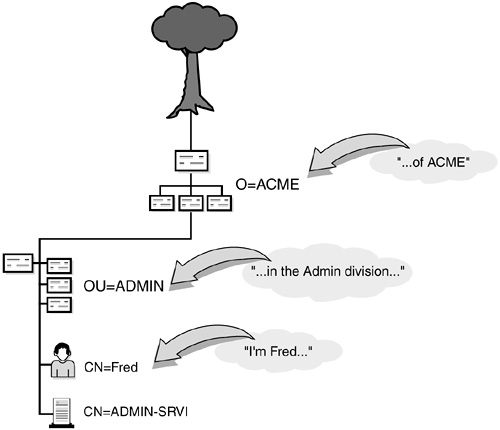
The whole NetWare 6 eDirectory naming scheme is much more complicated than “Hi, I’m Fred.” It requires both your name and location. For example, a proper eDirectory name would be “Hi, I’m Fred in the ADMIN division of ACME.” As you can see in Figure 19.7, Fred’s eDirectory name identifies who he is and where he works.
The eDirectory tree affects resource access because the organization of objects in the tree dictates how they can be found and used. In fact, the whole eDirectory naming strategy hinges on the concept of context. Context defines the position of an object within the Directory tree structure. When you request a particular network resource, you must identify the object’s context so that eDirectory can find it. Similar to locating files by using a DOS directory path, context represents a list of container objects leading from the object to the Tree Root. NetWare 6 uses specific naming guidelines for creating an object’s context.
REAL WORLD
Novell recommends that you create a document that describes your naming standards before you implement eDirectory. The eDirectory naming rules we’re going to learn here work only if object names are consistent across the network. A naming standards document provides guidelines for naming key container and leaf objects, including users, printers, servers, volumes, print queues, and organizational units. In addition, it identifies standard properties and value formats. Consistency, especially in the naming scheme used for objects, provides several benefits:
![]() A consistent naming scheme provides a guideline for network administrators who will add, modify, or move objects within the Directory tree.
A consistent naming scheme provides a guideline for network administrators who will add, modify, or move objects within the Directory tree.
![]() A naming standard eliminates redundant planning and gives network administrators an efficient model to meet their needs, but it leaves implementation of resource objects open and flexible.
A naming standard eliminates redundant planning and gives network administrators an efficient model to meet their needs, but it leaves implementation of resource objects open and flexible.
![]() Consistent naming schemes help users identify resources quickly, which maximizes user productivity.
Consistent naming schemes help users identify resources quickly, which maximizes user productivity.
![]() Consistent naming enables users to identify themselves easily during login.
Consistent naming enables users to identify themselves easily during login.
There are two main types of context: current context and object context. Check it out.
Current context is sometimes referred to as name context. It defines where you are in the eDirectory tree at any given time, not where you live. This is an important distinction. For example, if you’re using a NetWare 6 utility, it’s important to know what the utility considers as the current context in the eDirectory tree (that is, the default container to use if one isn’t specified). This concept is somewhat similar to knowing your current default drive/directory when using a DOS or Windows utility on your workstation.
In addition, current context affects how much of an object’s distinguished name you must provide to find it. (See the “Distinguished Names” section later in this chapter for more information.) Current context also enables you to refer to an object in your current container by its common name because the object’s context is the same. Note that current context always points to a container object rather than a leaf object. Typically, at login, you’ll want a workstation’s current context set to the container that holds the user’s most frequently used resources.
In Figure 19.7, Fred’s context is “...in the ADMIN division of ACME.” This context identifies where Fred lives in the eDirectory tree structure. It identifies all container objects leading from him to the Tree Root. In addition to context, Figure 19.7 identifies Fred’s common name (CN). A leaf object’s common name specifically identifies it within a given container. In this example, the User object’s common name is Fred.
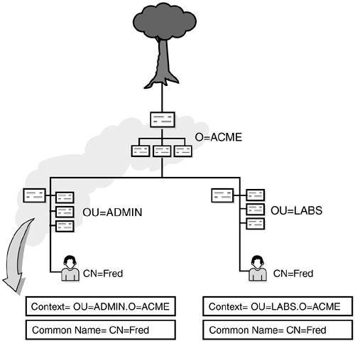
Two objects in the same eDirectory tree may have the same common name—provided, however, that they have different contexts. This is why naming is so important. As you can see in Figure 19.8, our eDirectory tree has two Freds, but each has a different context.
Object context (sometimes referred to as context) defines where a particular object is located in the eDirectory tree structure. It is a list of container objects leading from the object to the Tree Root. Locating an object through context is similar to locating a file using the directory path. As you learned earlier, object context is used for two important purposes: logging in and accessing resources. Unfortunately, eDirectory does not have a search path feature (such as NetWare SEARCH drives or the DOS PATH command used in the file system). This means that when you request a particular network resource, you (or your workstation) must provide eDirectory with enough information to locate the object in the tree.
Each eDirectory object has a naming type (also known as an attribute type) associated with it, which enables you to precisely identify objects in your tree. The tree organization obviously dictates how the objects can be located and used. This naming type is identified by a one- or two-character abbreviation. Accompanying the naming type is the value of the object, or the name you enter for the object when you create it. The following are examples of naming types and associated values:
![]() C = Country container
C = Country container
![]() O = Organization container
O = Organization container
![]() OU = Organizational Unit container
OU = Organizational Unit container
![]() CN = Common name (specifies a leaf object)
CN = Common name (specifies a leaf object)
The common name (CN) attribute is the name shown next to the leaf object in the eDirectory tree. This attribute applies to all leaf objects (servers, users, groups, and so on). When requesting a resource such as a server, the CN must be included in the request. Note: Common Names in eDirectory 8.7 behave slightly differently.
Now that you understand how eDirectory context works, let’s review the naming rules associated with it:
![]() Current context is a pointer to the eDirectory container that your Novell Client is currently set to.
Current context is a pointer to the eDirectory container that your Novell Client is currently set to.
![]() An object’s context defines its location in the eDirectory tree.
An object’s context defines its location in the eDirectory tree.
![]() Each object has an identifier abbreviation that defines it for naming purposes, namely the following: C = Country, O = Organization, OU = Organizational Unit, and CN = common name (of leaf object).
Each object has an identifier abbreviation that defines it for naming purposes, namely the following: C = Country, O = Organization, OU = Organizational Unit, and CN = common name (of leaf object).
![]() Context is defined by listing all containers from the object to the Tree Root, in that order. Each object is separated by a period.
Context is defined by listing all containers from the object to the Tree Root, in that order. Each object is separated by a period.
![]() Context is important for logging in and accessing eDirectory resources.
Context is important for logging in and accessing eDirectory resources.
So, there you have it. That’s how context works. With this in mind, it’s time to explore the two main types of eDirectory names: distinguished names and typeful names.
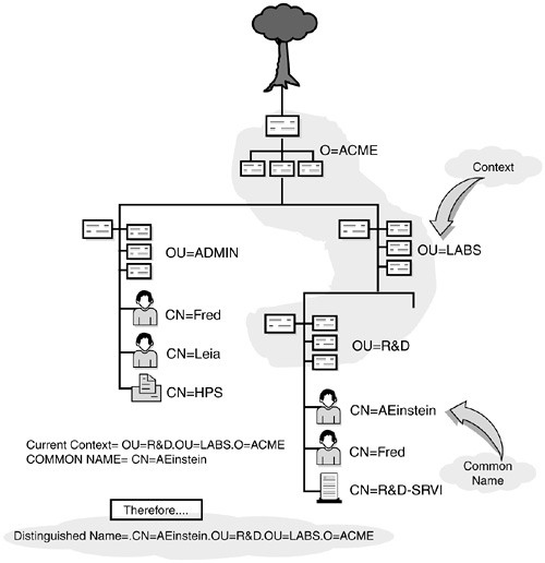
An object’s distinguished name is its complete eDirectory path. It is a combination of common name and object context. Each object in the eDirectory tree has a distinguished name that uniquely identifies it in the tree. In other words, two objects cannot have the same distinguished name.
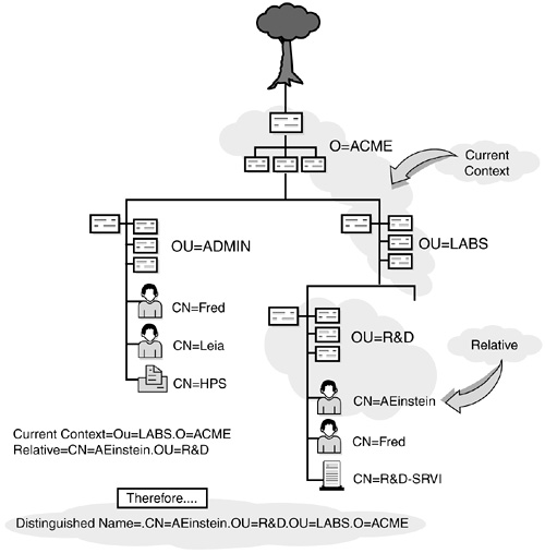
In Figure 19.9, AEinstein’s context is .OU=R&D.OU=LABS.O=ACME and his common name is CN=AEinstein. Therefore, Einstein’s distinguished name is a simple mathematical addition of the two:
.CN=AEinstein.OU=R&D.OU=LABS.O=ACME
Notice the use of periods. A distinguished name always starts with a leading period. Trailing periods aren’t allowed. The leading period identifies the name as distinguished (that is, complete). Otherwise, it is assumed to be incomplete or, in other words, a relative distinguished name.
A relative distinguished name (RDN) lists an object’s path to the current context, not the Tree Root. The relativity part refers to how eDirectory builds the distinguished name when you supply a relative name. By definition, for example, the common name of a leaf object is a relative distinguished name. When you use a relative distinguished name, eDirectory builds a distinguished name by appending the current context to the end:
Relative distinguished name + current context = distinguished name
For example, if the current context is .OU=LABS.O=ACME and you submit a relative distinguished name of CN=AEinstein.OU=R&D, the distinguished name would be resolved as (refer to Figure 19.10) the following:
.CN=AEinstein.OU=R&D.OU=LABS.O=ACME
To resolve a relative name, you must not lead with a period. Instead, you can use trailing periods to change the current context used to resolve the name (as if naming weren’t hard enough already). The bottom line is that each trailing period tells eDirectory to remove one object name from the left side of the current context being used. This concept is somewhat similar to the trailing dot feature used in the DOS CD command.
For example, assume that .OU=R&D.OU=LABS.O=ACME is your current context and that CN=LEIA.OU=ADMIN.. is your relative distinguished name. In this case, the distinguished name would resolve as follows (refer to Figure 19.11):
.CN=LEIA.OU=ADMIN.O=ACME

As you can see, it’s very important where you place your dots! Here’s a quick summary:
![]() All objects in an eDirectory name are separated by dots.
All objects in an eDirectory name are separated by dots.
![]() Distinguished names are preceded by a dot. This identifies them as complete.
Distinguished names are preceded by a dot. This identifies them as complete.
![]() Relative distinguished names are not preceded by a dot. This identifies them as incomplete.
Relative distinguished names are not preceded by a dot. This identifies them as incomplete.
![]() Trailing dots can be used only in relative distinguished names because they modify the current context to be used. Each dot moves the context up one container as the distinguished name is resolved.
Trailing dots can be used only in relative distinguished names because they modify the current context to be used. Each dot moves the context up one container as the distinguished name is resolved.
For a complete summary of eDirectory distinguished naming rules, refer to Table 19.3.

Now, let’s step back into reality for a moment and explore the other eDirectory naming category—typeful and typeless names.
Typeful names use attribute type abbreviations to distinguish between the different container types and leaf objects in eDirectory names. In all the examples to this point, we’ve used these abbreviations to help clarify context, distinguished names, and relative distinguished names. The following are the most popular attribute type abbreviations:
![]() C = Country container
C = Country container
![]() O = Organization container
O = Organization container
![]() OU = Organizational Unit container
OU = Organizational Unit container
![]() CN = Common name of a leaf object
CN = Common name of a leaf object
These attribute types help avoid the confusion that can occur when creating complex distinguished and relative distinguished names. I highly recommend that you use them. Of course, like most things in life—they’re optional! You can imagine how crazy eDirectory naming gets when you choose not to use these attribute abbreviations. This insanity is known as typeless naming.
Typeless names operate the same as typeful names, but they don’t include object attribute types. In such cases, eDirectory has to guess what object types you’re using. Take the following typeless name, for example:
.Admin.ACME
Is this the ADMIN Organizational Unit under ACME? Or is this the Admin user under ACME? In both cases, it’s a valid distinguished name, except that one identifies an Organizational Unit container and the other identifies a User leaf object (refer to Figure 19.12).
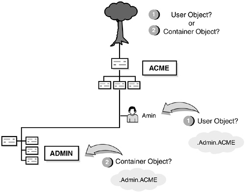
Well, here’s the bottom line: which one is it? It’s up to eDirectory. If you don’t provide a typeful object name, eDirectory calculates attribute types for each object. Fortunately, NetWare 6 has some guidelines for guessing what the object type should be.
![]() The leftmost object is a common name (leaf object).
The leftmost object is a common name (leaf object).
![]() The rightmost object is an Organization (container object).
The rightmost object is an Organization (container object).
![]() All middle objects are Organizational Units (container objects).
All middle objects are Organizational Units (container objects).
Although this works for most cases, it’s only a general guideline. Many times, typeless names are more complex. Consider our example in Figure 19.12, for instance. We know now that the rightmost object is an Organization, but what about Admin? Is it a common name or an Organizational Unit? We still don’t know. Fortunately, NetWare 6 includes a few exceptions to deal with complex typeless scenarios. Here’s how it works:
![]() Exception rule 1: container objects—Many NetWare 6 utilities are intelligent enough to resolve typeless names, depending on what they’re trying to accomplish. CX, for example, is used primarily for changing context. If you apply the CX command to a typeless name, it assumes the leftmost object is an Organization or Organizational Unit. This is because you can’t change your current context to a leaf object. ConsoleOne is the best graphical utility for changing your context. In summary, here’s how our example from Figure 19.12 would look with the CX utility:
Exception rule 1: container objects—Many NetWare 6 utilities are intelligent enough to resolve typeless names, depending on what they’re trying to accomplish. CX, for example, is used primarily for changing context. If you apply the CX command to a typeless name, it assumes the leftmost object is an Organization or Organizational Unit. This is because you can’t change your current context to a leaf object. ConsoleOne is the best graphical utility for changing your context. In summary, here’s how our example from Figure 19.12 would look with the CX utility:
CX .ADMIN.ACME resolves as ".OU=ADMIN.O=ACME"
![]() Exception rule 2: leaf objects—Similarly, resource-based utilities recognize the leftmost object of a typeless name as a leaf object. Many of these utilities expect to see a common name. The most prevalent are LOGIN, MAP, and CAPTURE. Here’s how it works for our example in Figure 19.12:
Exception rule 2: leaf objects—Similarly, resource-based utilities recognize the leftmost object of a typeless name as a leaf object. Many of these utilities expect to see a common name. The most prevalent are LOGIN, MAP, and CAPTURE. Here’s how it works for our example in Figure 19.12:
LOGIN .Admin.ACME resolves as ".CN=Admin.O=ACME"
![]() Exception rule 3: contextless login—If you have Catalog Services and Contextless Login activated, eDirectory will resolve typeless names by offering the user a list from the eDirectory catalog. (Note: NetWare 6 eDirectory does not support Catalog Services.)
Exception rule 3: contextless login—If you have Catalog Services and Contextless Login activated, eDirectory will resolve typeless names by offering the user a list from the eDirectory catalog. (Note: NetWare 6 eDirectory does not support Catalog Services.)
There you have it. This completes our discussion of typeless names and eDirectory naming in general. As you can see, this is an important topic because it affects all aspects of eDirectory design, installation, and management. No matter what you do, you’re going to have to use the correct name to log in to the tree or access eDirectory resources. As you’ve learned, an object’s name is a combination of what it is (common name) and where it lives (context).
Now, let’s build a naming standards document.
The following are some guidelines you should consider when creating your eDirectory naming standards document:
![]() Make browsing and navigation of the eDirectory tree easier for users
Make browsing and navigation of the eDirectory tree easier for users
![]() Make maintenance of the eDirectory tree easier for network administrators
Make maintenance of the eDirectory tree easier for network administrators
![]() Make merging separate eDirectory trees easier
Make merging separate eDirectory trees easier
![]() Keep eDirectory object names unique
Keep eDirectory object names unique
![]() Avoid special characters reserved by operating systems
Avoid special characters reserved by operating systems
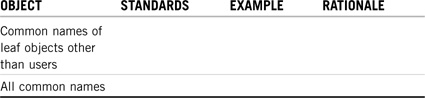
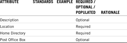
The eDirectory naming standards document consists of two eDirectory components: objects and properties. The eDirectory object naming standard contains a list of the object types present in your eDirectory tree, as well as a consistent naming scheme for each object type (see Table 19.4). The eDirectory property naming standard defines required properties for each object type, a consistent property-naming scheme, and examples of each property type (see Table 19.5).


eDirectory tree design begins with an object naming standard. Begin by taking a long, hard look at ACME and the network resources it uses. Consider the affect of naming on these resources and come up with some simple guidelines for standardizing the names. The good news is that most of your effort is focused on a few leaf and container objects, namely the following:
![]() Users—When creating a naming standard, the first step is to decide what to do with the users. eDirectory allows usernames up to 64 characters long. However, a 64-character username is ridiculous. Consider limiting it to eight characters or fewer. This is appropriate in many cases, but not ACME. The eight-character rule makes file system management much easier, but it hinders the identity and exclusivity of key users. It’s important to ensure that each username is unique throughout a company. Even though eDirectory doesn’t require it, exclusivity aids messaging management.
Users—When creating a naming standard, the first step is to decide what to do with the users. eDirectory allows usernames up to 64 characters long. However, a 64-character username is ridiculous. Consider limiting it to eight characters or fewer. This is appropriate in many cases, but not ACME. The eight-character rule makes file system management much easier, but it hinders the identity and exclusivity of key users. It’s important to ensure that each username is unique throughout a company. Even though eDirectory doesn’t require it, exclusivity aids messaging management.
![]() Organization—Your Organization name should reflect your company name. In our case, A Cure for Mother Earth becomes ACME, and the Organization name becomes O=ACME. With the Organization restricted to the company’s name, the Organizational Units are free to become the true Tupperware containers of eDirectory logic. In addition, you might consider adding a location to the Organization name and accommodate future tree merging.
Organization—Your Organization name should reflect your company name. In our case, A Cure for Mother Earth becomes ACME, and the Organization name becomes O=ACME. With the Organization restricted to the company’s name, the Organizational Units are free to become the true Tupperware containers of eDirectory logic. In addition, you might consider adding a location to the Organization name and accommodate future tree merging.
![]() Organizational Units—Organizational Units can span multiple container depths. With this flexibility, they can be used for geography and organization. As you’ll learn in the next section, geography defines the upper layers of the eDirectory tree. So, the first few layers of Organizational Units should be reserved for locations, such as OU=SYDNEY and OU=TOKYO. They could have been abbreviated to SYD and TOK, but their names are already short. Remember, the names must be both short and descriptive (SYD isn’t very descriptive). The next OU layers are dedicated to divisions and departments, such as OU=R&D for the Research & Development department and OU=MRKT for Marketing. Remember: be short, but descriptive. This allows for much easier tree searching and navigation.
Organizational Units—Organizational Units can span multiple container depths. With this flexibility, they can be used for geography and organization. As you’ll learn in the next section, geography defines the upper layers of the eDirectory tree. So, the first few layers of Organizational Units should be reserved for locations, such as OU=SYDNEY and OU=TOKYO. They could have been abbreviated to SYD and TOK, but their names are already short. Remember, the names must be both short and descriptive (SYD isn’t very descriptive). The next OU layers are dedicated to divisions and departments, such as OU=R&D for the Research & Development department and OU=MRKT for Marketing. Remember: be short, but descriptive. This allows for much easier tree searching and navigation.
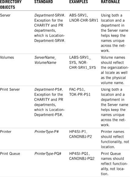
![]() Servers—Server names must be unique across the entire WAN because of Service Location Protocol (SLP) and Routing Information Protocol (RIP) broadcasting. You might want to consider a server name that incorporates both its location and department. For ACME, a NetWare 6 server in the CHARITY department of NORAD is called NOR-CHR-SRV1 and a print server is called NOR-CHR-PS1. On the other hand, a file server in the R&D department of NORAD is called R&D-SRV1 because R&D is a unique department within the ACME tree and, therefore, it doesn’t need any special location designator. However, the CHARITY and PR departments are not unique departments—they exist in each location throughout the ACME tree. Therefore, the servers in those containers should use the location designator to uniquely identify them.
Servers—Server names must be unique across the entire WAN because of Service Location Protocol (SLP) and Routing Information Protocol (RIP) broadcasting. You might want to consider a server name that incorporates both its location and department. For ACME, a NetWare 6 server in the CHARITY department of NORAD is called NOR-CHR-SRV1 and a print server is called NOR-CHR-PS1. On the other hand, a file server in the R&D department of NORAD is called R&D-SRV1 because R&D is a unique department within the ACME tree and, therefore, it doesn’t need any special location designator. However, the CHARITY and PR departments are not unique departments—they exist in each location throughout the ACME tree. Therefore, the servers in those containers should use the location designator to uniquely identify them.
![]() Printers and Print Queues—Unlike servers, printers and print queues don’t require naming exclusivity. The department and location information is obtained through the object’s eDirectory context. This means that an HP LaserJet 4SI in R&D can share the same name as an HP LaserJet 4SI in WHITE—they have different distinguished names because they have different parent containers. In summary, a printer’s distinguished name identifies its location and department. Therefore, printer and print queue names should reflect functionality, not location. Also, make sure to build Printer names that accommodate new NetWare 6 printing technology, such as NDPS and iPrint. See Chapter 20 for some great eDirectory printing accessibility lessons.
Printers and Print Queues—Unlike servers, printers and print queues don’t require naming exclusivity. The department and location information is obtained through the object’s eDirectory context. This means that an HP LaserJet 4SI in R&D can share the same name as an HP LaserJet 4SI in WHITE—they have different distinguished names because they have different parent containers. In summary, a printer’s distinguished name identifies its location and department. Therefore, printer and print queue names should reflect functionality, not location. Also, make sure to build Printer names that accommodate new NetWare 6 printing technology, such as NDPS and iPrint. See Chapter 20 for some great eDirectory printing accessibility lessons.
You should keep the following in mind:
![]() Use unique eDirectory object names within a container.
Use unique eDirectory object names within a container.
![]() Any information you use to search the eDirectory database must be included in your naming standards.
Any information you use to search the eDirectory database must be included in your naming standards.
![]() If you have users whose workstations are configured to use different languages, you might want to limit object names to characters that can be viewed on all workstations across the network.
If you have users whose workstations are configured to use different languages, you might want to limit object names to characters that can be viewed on all workstations across the network.
![]() Be sure to name your tree by using the basic ASCII character set. Do not use extended or other special characters in your tree name.
Be sure to name your tree by using the basic ASCII character set. Do not use extended or other special characters in your tree name.
Creating an eDirectory naming standards document for objects is as easy as 1-2-3-4:
1. List each type of object used in the eDirectory tree
2. Specify the standard you will use for each object type
3. Provide a brief example for each object type used
4. Specify the rationale for each object type selected
This completes our discussion of the main eDirectory object classes. In addition, you might want to consider naming standards for Group, Organizational Role, Directory Map Object, and Profile objects. Refer to Table 19.4 for a detailed summary of ACME’s eDirectory object naming standard.
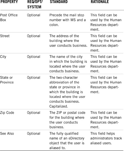
The final step is to put your naming guidelines under the microscope. Now you must focus in on each object class and provide rules for required, optional, and system properties.
First, determine which properties should be required. Start with the mandatory eDirectory properties and expand from there. For example, eDirectory won’t allow you to create a User object without the Login Name and Last Name properties. In ACME’s case, we’re also requiring Given Name, Full Name, Middle Initial, Title, Location, Telephone Number, Fax Number, Home Directory, and Require Password.
Next, determine which properties will be optional. Finally, identify system properties (such as Network Address and so on). In addition, you’ll want to provide naming rules for how the properties look. Refer to Table 19.5 for a detailed summary of ACME’s eDirectory property naming standard.
TIP
Currently, NetWare 6 utilities can’t be configured to enforce additional required properties. The User object, for example, is only required to have a Login Name and Last Name. Your standard, however, might be different. You’ll need to enforce required user properties at the management level—in your naming guidelines. Also, it helps if you explain the reasoning for including the property. This helps distributed administrators buy into it. Finally, you might want to consider extending the eDirectory schema to support additional required properties using the eDirectory Schema Manager.
After you’ve completed the naming guidelines and examples, there’s only one more set of rules to complete your naming standards document: syntax. Table 19.6 shows a simple but effective syntax standard. Notice that I’ve also included examples. In the most basic sense, this is a summary of the entire naming standards document. Small organizations could probably get away with using just the naming syntax guidelines.

Here’s the legend for Table 19.6:
![]() AAAA—Company Name
AAAA—Company Name
![]() XXX—Location (NOR, RIO, CAM, TOK, SYD)
XXX—Location (NOR, RIO, CAM, TOK, SYD)
![]() YYYYY—Department (LABS, CHR, PR, ADM, OPS, FIN)
YYYYY—Department (LABS, CHR, PR, ADM, OPS, FIN)
![]() SRV—File Server
SRV—File Server
![]() PS—Print Server
PS—Print Server
![]() #—Quantity (1, 2, 3,..., 9)
#—Quantity (1, 2, 3,..., 9)
![]() Volumes—SYS, VOL1, DATA, USERS, SHARE
Volumes—SYS, VOL1, DATA, USERS, SHARE
Congratulations! You’ve completed the ACME naming standards document. What an accomplishment. It wasn’t easy, but now you should feel much more comfortable about the future of ACME’s design. At the very least, we know what to call eDirectory objects and their properties.
The next step is eDirectory tree design. This is when you get a chance to establish rules for tree design, just as you did for naming standards. Have fun.
This exercise provides you with an opportunity to write a few standards for naming objects and object attribute requirements.
In this exercise, you do the following:
![]() Part I: Create Additional Common Name Object Naming Standards for ACME
Part I: Create Additional Common Name Object Naming Standards for ACME
![]() Part II: Create Additional Attribute Standards for ACME User Objects
Part II: Create Additional Attribute Standards for ACME User Objects
Use the ACME profile and organizational chart presented in Chapter 18, and the guidelines and examples in this chapter as reference material.
Test Objectives Covered:
![]() Design the Upper Layers of the eDirectory Tree
Design the Upper Layers of the eDirectory Tree
![]() Design the Lower Layers of the eDirectory Tree
Design the Lower Layers of the eDirectory Tree
![]() Identify Fundamental Directory Design Factors
Identify Fundamental Directory Design Factors
eDirectory tree design is the most important phase in the design and implementation process. Most general eDirectory design benefits stem from a well-planned Directory tree, including the following improvements:
![]() Partitioning and replication can be successfully designed.
Partitioning and replication can be successfully designed.
![]() The network can accommodate growth without complicating revisions.
The network can accommodate growth without complicating revisions.
![]() Directory trees can be merged more easily.
Directory trees can be merged more easily.
![]() Other network services and network accessibility can be designed more easily.
Other network services and network accessibility can be designed more easily.
![]() The directory tree can be navigated more intuitively.
The directory tree can be navigated more intuitively.
For most small to medium sized organizations, a single tree works best because you have a single user identity on the network, simpler administration of security, and a single point of management. This does not preclude the need for additional trees dedicated to testing and development, however.
You should take extra caution in designing the top layers of the tree because changes here can have a large effect on the placement of resources lower in the tree. Furthermore, this importance is amplified when the network spans WAN links.
To build an efficient eDirectory tree design, you should follow these three steps:
![]() Step 1: Use a pyramid design—Design the eDirectory tree in the shape of a pyramid.
Step 1: Use a pyramid design—Design the eDirectory tree in the shape of a pyramid.
![]() Step 2: Design the top layers—Use a single Organization object and design the top layers of the tree according to location and network infrastructure.
Step 2: Design the top layers—Use a single Organization object and design the top layers of the tree according to location and network infrastructure.
![]() Step 3: Design the bottom layers—Design the bottom layers of the tree according to organization and function.
Step 3: Design the bottom layers—Design the bottom layers of the tree according to organization and function.
Before you can begin building your eDirectory tree design, you must pull together the required design inputs. In Chapter 18, we discovered eight different design inputs in two different categories (organizational and technical). In this section, we’re very interested in the following five ACME inputs:
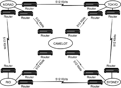
![]() ACME WAN layout—The WAN layout consists of all your major hub locations and their interconnected routers and bridges (see Figure 19.13). Notice in ACME’s WAN layout map that all five main sites are shown with their router connections and the speed of these links in kilobits (Kbits) per second. Your WAN layout map might look similar, and it might additionally include the link speeds of your satellite offices (or distribution centers, in our case). This document is necessary for the upper-layer design of your tree, as I’ll explain in step 2. Most companies have some sort of WAN map, but you might have to draw a new one. Try to consolidate all the important interconnectivity information in a single overview.
ACME WAN layout—The WAN layout consists of all your major hub locations and their interconnected routers and bridges (see Figure 19.13). Notice in ACME’s WAN layout map that all five main sites are shown with their router connections and the speed of these links in kilobits (Kbits) per second. Your WAN layout map might look similar, and it might additionally include the link speeds of your satellite offices (or distribution centers, in our case). This document is necessary for the upper-layer design of your tree, as I’ll explain in step 2. Most companies have some sort of WAN map, but you might have to draw a new one. Try to consolidate all the important interconnectivity information in a single overview.
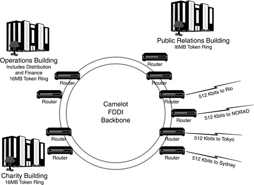
![]() ACME campus maps—The WAN layout provides a great interconnectivity overview, but it’s not enough. You’ll need campus maps for each major hub site. The campus maps should show the type of information illustrated in Figure 19.14. This is ACME’s campus map for the CAMELOT hub. The ACME campus map for CAMELOT shows a fiber distributed data interface (FDDI) ring and routers connecting the distributed buildings. The ACME WAN layout shows a network in CAMELOT and a list of sites within the CAMELOT area, such as an operations center (OPS) located at the northwest end of the city and a public relations office (PR) located in the downtown district. An office for charitable contributions (CHR) is also found at the southwest end of the city. Campus maps are important because they refine ACME’s WAN/LAN infrastructure. We need the campus maps to organize the second tier of ACME’s top layers.
ACME campus maps—The WAN layout provides a great interconnectivity overview, but it’s not enough. You’ll need campus maps for each major hub site. The campus maps should show the type of information illustrated in Figure 19.14. This is ACME’s campus map for the CAMELOT hub. The ACME campus map for CAMELOT shows a fiber distributed data interface (FDDI) ring and routers connecting the distributed buildings. The ACME WAN layout shows a network in CAMELOT and a list of sites within the CAMELOT area, such as an operations center (OPS) located at the northwest end of the city and a public relations office (PR) located in the downtown district. An office for charitable contributions (CHR) is also found at the southwest end of the city. Campus maps are important because they refine ACME’s WAN/LAN infrastructure. We need the campus maps to organize the second tier of ACME’s top layers.
![]() ACME world location map—The last map is a big one. It provides a global view of ACME and its distributed locations. Each hub site, building, and distribution center should be integrated into one ACME world location map. This provides a snapshot of the ACME geography and becomes the foundation of the top layers of ACME’s tree. In addition, this information combines with the ACME WAN layout to determine whether regional containers are necessary. Refer to Figure 18.13 in Chapter 18 for a picture of ACME’s world location map.
ACME world location map—The last map is a big one. It provides a global view of ACME and its distributed locations. Each hub site, building, and distribution center should be integrated into one ACME world location map. This provides a snapshot of the ACME geography and becomes the foundation of the top layers of ACME’s tree. In addition, this information combines with the ACME WAN layout to determine whether regional containers are necessary. Refer to Figure 18.13 in Chapter 18 for a picture of ACME’s world location map.
![]() ACME resource list—The final technical input is the ACME resource list. This list gives valuable information about the servers and printers found in each region, site, building, and department. Table 18.2 in Chapter 18 shows the original ACME resource wish list. The updated ACME resource list in Table 19.9 has been rewritten to include the naming standards discussed previously. Additionally, appropriate administrator, servers, and printers have been distributed to their proper locations, as per the WAN layout and campus maps. Study this list carefully; everything we do from now on will center on these critical resources. This is the foundation of step 3.
ACME resource list—The final technical input is the ACME resource list. This list gives valuable information about the servers and printers found in each region, site, building, and department. Table 18.2 in Chapter 18 shows the original ACME resource wish list. The updated ACME resource list in Table 19.9 has been rewritten to include the naming standards discussed previously. Additionally, appropriate administrator, servers, and printers have been distributed to their proper locations, as per the WAN layout and campus maps. Study this list carefully; everything we do from now on will center on these critical resources. This is the foundation of step 3.

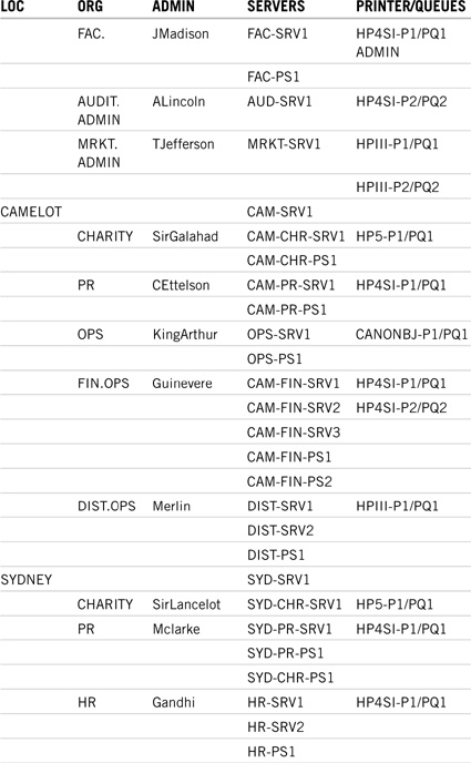
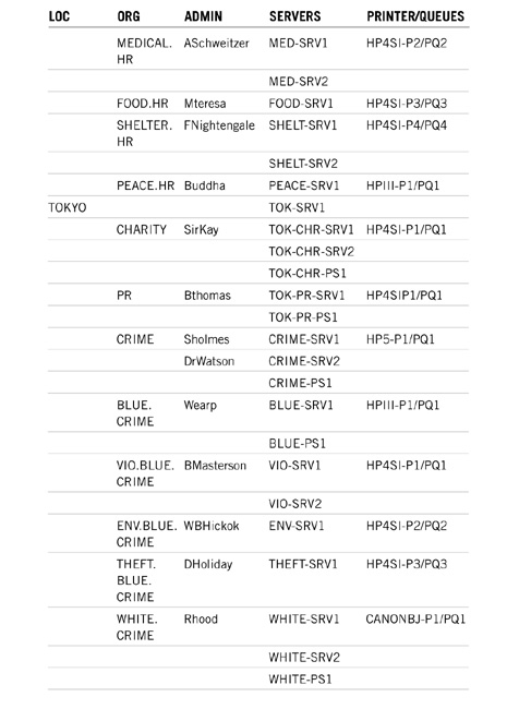

![]() ACME organizational chart—This brings us to the final design input—ACME’s organizational chart (refer to Figure 18.5 in Chapter 18). Some companies have pages of organizational charts. Try not to get too wrapped up in them. Your main purpose here is to identify divisions, departments, or other organizational workgroups. Also, use the work flow diagram (refer to Figure 18.11 in Chapter 18) to identify auxiliary workgroups throughout the WAN. These divisions, departments, and workgroups will become the foundation of ACME’s bottom layers—step 3.
ACME organizational chart—This brings us to the final design input—ACME’s organizational chart (refer to Figure 18.5 in Chapter 18). Some companies have pages of organizational charts. Try not to get too wrapped up in them. Your main purpose here is to identify divisions, departments, or other organizational workgroups. Also, use the work flow diagram (refer to Figure 18.11 in Chapter 18) to identify auxiliary workgroups throughout the WAN. These divisions, departments, and workgroups will become the foundation of ACME’s bottom layers—step 3.
TIP
Resist the temptation to design your tree around the organizational chart. This mistake is more common than you think, mostly because the chart is the only design input people understand. It’s also the only design input available in many cases. I know it’s more work, but develop technical inputs for your organization and use them for your tree design. You’ll thank me in the long run, especially when it comes time to design partitions and replica placement.
Keep in mind that few companies document their WAN to this extent. You might even have to create a few design inputs yourself. But it’s worth it. Nothing’s harder than trying to design the tree without them. These documents are the driving forces of the entire eDirectory design process.
Speaking of the process, let’s start with step 1: the pyramid.
The overall eDirectory tree design should form the shape of a pyramid (or inverted tree). This type of design places most of the objects at the bottom of the structure and the fewest containers at the top (see Figure 19.15). In eDirectory, rights flow down, not up or across, which the pyramid design facilitates quite nicely. The pyramid design should be split into two sections:
![]() Top—The top of the tree should reflect the physical structure of the network because it builds a solid foundation for the bottom layers. This is the static section of the design where few changes are made.
Top—The top of the tree should reflect the physical structure of the network because it builds a solid foundation for the bottom layers. This is the static section of the design where few changes are made.
Another advantage of static top layers is natural partitioning, which means that partition boundaries can flow naturally and subordinate reference replicas are minimized.
![]() Bottom—The bottom of the tree is defined by the local area network (LAN) structure and is based on the functional organization of the company. This can be accomplished by planning around divisions, departments, and company workgroups. The bottom layer containers will hold the majority of the company’s eDirectory objects, including users, file servers, printers, print queues, and other network resources. Finally, using this strategy, the bottom layers of the tree will be more dynamic and will give you the flexibility to change the tree when necessary.
Bottom—The bottom of the tree is defined by the local area network (LAN) structure and is based on the functional organization of the company. This can be accomplished by planning around divisions, departments, and company workgroups. The bottom layer containers will hold the majority of the company’s eDirectory objects, including users, file servers, printers, print queues, and other network resources. Finally, using this strategy, the bottom layers of the tree will be more dynamic and will give you the flexibility to change the tree when necessary.
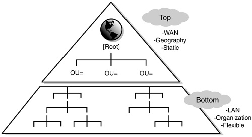
An alternative to the pyramid design is a flat tree that places all eDirectory objects in the top layers (refer to Figure 19.16). With all eDirectory objects at the top of the tree, your Directory tree will become inefficient. A flat tree is not recommended because of the way it must be partitioned and replicated. This type of design tends to create increased synchronization traffic. A large number of subordinate reference replicas might also occur.
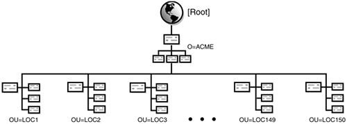
TIP
Study the benefits of a well-designed eDirectory tree, specifically that partitioning and replication can be designed successfully, the network can accommodate growth without complicating revisions, and directory trees can be merged more easily. In addition, learn the purpose of each of the two halves of the pyramid tree design: physical (top) and functional (bottom).
Now that you understand the rough pyramid shape of ACME’s tree, let’s take a closer look at the top and bottom layers. Remember, each half serves a unique and special purpose.
As in most things, the top is the most important half. It is the foundation of ACME’s eDirectory tree design—the rest of the tree branches downward from there. The top layers of the eDirectory tree typically include the following three container types (see Figure 19.17):
![]() [Root]—The [Root] is the top of the eDirectory tree and defines the tree itself. Therefore, you cannot have duplicate tree names within the same network.
[Root]—The [Root] is the top of the eDirectory tree and defines the tree itself. Therefore, you cannot have duplicate tree names within the same network.
![]() O=Organization—An Organization object is used to define a corporation, association, university, operating division, and so on. Generally, you should create only one Organization object per eDirectory tree. However, there are instances when the use of multiple Organization objects is justified.
O=Organization—An Organization object is used to define a corporation, association, university, operating division, and so on. Generally, you should create only one Organization object per eDirectory tree. However, there are instances when the use of multiple Organization objects is justified.
![]() OU=Organizational Units—Organizational Unit objects provide structure to the top of the eDirectory tree. OUs can be designed according to location, function, or region.
OU=Organizational Units—Organizational Unit objects provide structure to the top of the eDirectory tree. OUs can be designed according to location, function, or region.
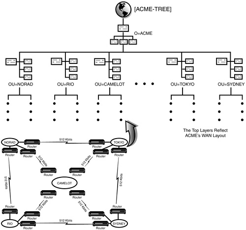
First, you must name the tree itself. The tree name is represented by the [Root] object, which is placed at the top of the eDirectory pyramid. A good strategy is to create a tree name that consists of the name of your organization name plus -TREE. For example, our company is called ACME, so we named the tree ACME-TREE (refer to Figure 19.17).
The tree name must be unique. If you need to install more than one logical tree on the same physical network, be sure that the trees have different names. You can change the name of the tree after initial eDirectory installation, if necessary, by using the DSMERGE utility. Changing the tree name has a greater effect on larger networks because it requires a great deal of effort to reconfigure clients to use the new tree name.
The Organization layer defines the company and its purpose. All other geographic and organizational functions are provided by lower Organizational Unit layers. A good strategy is to use an abbreviation of your organization’s name as the name of the Organization object. For example, our company is named A Cure for Mother Earth, which is abbreviated to ACME (see Figure 19.17).
Using a single Organization container provides an excellent tool for distributing management policies throughout the entire company. For example, you can implement a workstation-naming convention from your eDirectory naming standards document by creating ZENworks Workstation Import Policy objects and placing them at the Organization level. In this policy, you can define how Workstation objects are named when they’re created in eDirectory. In this case, the policy would affect the whole company. See Figure 19.18 for an example of a single O=ACME Organization tree design.
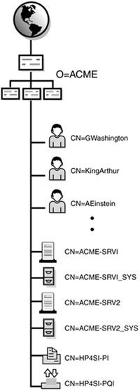
Limiting your eDirectory tree to a single Organization object is not a requirement. Following are a few exceptions that could justify the use of multiple Organization containers:
![]() Some multinational conglomerates consist of different companies that operate independently. In that case, you might want to create an Organization container for each company.
Some multinational conglomerates consist of different companies that operate independently. In that case, you might want to create an Organization container for each company.
![]() Some companies track financial performance according to business units or divisions. In that case, multiple Organizations enable administrators to track network resources separately.
Some companies track financial performance according to business units or divisions. In that case, multiple Organizations enable administrators to track network resources separately.
![]() Some companies have other business reasons or internal guidelines that force divisions to operate independently.
Some companies have other business reasons or internal guidelines that force divisions to operate independently.
In Figure 19.19, we’ve combined ACME and the UN into a single eDirectory tree. In this example, the two multinational conglomerates (ACME and UN) include many different locations, each of which operates independently of each other. As you can see in the figure, we’ve created an O=Organization for each corporation.

The final top layers are defined by Organizational Unit containers. These are the most important layers in the tree because they represent a transition point between the inflexible upper layers and the flexible bottom layers. These OU layers also define the layout of the rest of the tree. In summary, this is where your tree begins to take shape.
You can choose one of three approaches for the final tier of the top layers:
![]() Geographic—Organize the upper layers according to ACME’s WAN layout map and distributed sites. This is the preferred eDirectory architecture.
Geographic—Organize the upper layers according to ACME’s WAN layout map and distributed sites. This is the preferred eDirectory architecture.
![]() Regional—Insert regional containers to further organize numerous distributed sites.
Regional—Insert regional containers to further organize numerous distributed sites.
![]() Functional—Organize the upper layers according to ACME’s organizational chart and departmental workgroups.
Functional—Organize the upper layers according to ACME’s organizational chart and departmental workgroups.
The first approach is based on the geographic boundaries (or location) of your WAN. Remember, the sole purpose of the eDirectory tree is to productively organize network resources. These resources are geographically distributed and rely on slow WAN links for interconnectivity. Basing your organization on geographic boundaries provides a natural place in the eDirectory to make security and administrator assignments for each location. To optimize partitioning, replica placement, and time synchronization, you should design the first layer of OUs along these WAN boundaries.
As a matter of fact, the dynamic nature of eDirectory essentially forces you to design the top layers of the tree according to geography. Some reasons include the following:
![]() A design based on geography reflects the WAN infrastructure.
A design based on geography reflects the WAN infrastructure.
![]() It minimizes WAN traffic and related costs.
It minimizes WAN traffic and related costs.
![]() It facilitates partitioning because the WAN design provides a structure for partitions.
It facilitates partitioning because the WAN design provides a structure for partitions.
![]() It reduces significant future changes to the directory tree because locations are fairly permanent.
It reduces significant future changes to the directory tree because locations are fairly permanent.
![]() It places the physical network resources near the users and groups that need them.
It places the physical network resources near the users and groups that need them.
The geographic approach relies on your WAN layout map. As you could see in Figure 19.13, ACME is organized around five main hubs: CAMELOT, RIO, SYDNEY, TOKYO, and NORAD. These hubs become the foundation of ACME’s OU structure, as shown in Figure 19.17. After you’ve established the geographic top of the tree, you can zero in on each location with an organizational design—at the bottom layers.
Of course, life is full of exceptions, and the geographic approach is not always the best answer. Following are three exceptions to consider:
![]() Exception 1—Companies with a single site or local campus network are not dependent upon the geographic design approach. Because there’s little geography with which to work, you should skip the geographic layers and go straight to organization. Some companies with few servers and users might not need to create additional containers at all. Rather, they can place all the eDirectory objects under a single O=Organization (see Figure 19.18).
Exception 1—Companies with a single site or local campus network are not dependent upon the geographic design approach. Because there’s little geography with which to work, you should skip the geographic layers and go straight to organization. Some companies with few servers and users might not need to create additional containers at all. Rather, they can place all the eDirectory objects under a single O=Organization (see Figure 19.18).
![]() Exception 2—Companies with WAN sites or local campuses connected with very high-speed links (such as T-3 or greater). In this type of environment, the location of OU layers is less important because the limiting, slow WAN links have been removed. In this case, the very high bandwidths nullify geographic considerations.
Exception 2—Companies with WAN sites or local campuses connected with very high-speed links (such as T-3 or greater). In this type of environment, the location of OU layers is less important because the limiting, slow WAN links have been removed. In this case, the very high bandwidths nullify geographic considerations.
![]() Exception 3—If you’re considering making a dial-up remote location part of your eDirectory tree, be sure to weigh the costs involved. You can incur significant costs when a dial-up remote location is placed in an organizationwide eDirectory tree. You should consider issues regarding time synchronization, partitioning, and replica placement before including dial-up remote locations in your tree.
Exception 3—If you’re considering making a dial-up remote location part of your eDirectory tree, be sure to weigh the costs involved. You can incur significant costs when a dial-up remote location is placed in an organizationwide eDirectory tree. You should consider issues regarding time synchronization, partitioning, and replica placement before including dial-up remote locations in your tree.
If you’re using a campus layout (such as a research park or university), first consider the speed of the links between buildings or floors. The geographic approach could still be used with buildings representing minor OU sites within the network infrastructure. Even in ACME’s case, the distributed campus buildings could be useful second-tier container objects—as long as they help organize the network resources.
The second approach relies on the introduction of regional containers above the geographic OU layers. This is necessary if the total number of locations is high—10 to 15 subcontainers per location, for example. Adding an intermediate regional layer helps to ensure a balanced pyramid design.
Consider what happens when ACME decides to expand. Let’s say it decides to integrate more offices throughout the world. In this example only, ACME’s WAN infrastructure would look something like Figure 19.20. Notice that the distributed offices connect together via 56-Kbit links, whereas the hubs still use 512-Kbit lines. Also, each city is added to the WAN layout through their appropriate regional hub.
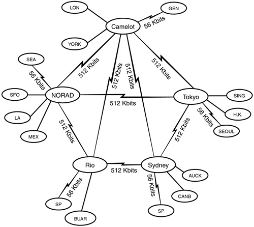
Using the WAN infrastructure, we’ve designed a new tree that includes regional OUs named North America (NA), South America (SA), Europe (EUR), Asia (ASIA), and Australia (AUST). These regional OU layers group the appropriate cities and help keep the eDirectory tree design looking like a pyramid (see Figure 19.21).
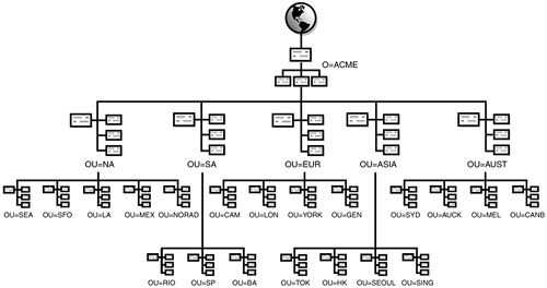
The final option is based on functional workgroups throughout your company. This functional approach should only be used in the following two cases:
![]() Case 1—Your company doesn’t have a WAN infrastructure or other locations to worry about. If your company operates over a LAN or high-speed WAN, you can skip the geographic design and go directly to the organizational bottom-layer design. This approach is based solely on the organizational chart.
Case 1—Your company doesn’t have a WAN infrastructure or other locations to worry about. If your company operates over a LAN or high-speed WAN, you can skip the geographic design and go directly to the organizational bottom-layer design. This approach is based solely on the organizational chart.
![]() Case 2—You’re a rebel, and you really want to design your tree according to the company’s organizational chart. This approach is justified if there is something very special about your company—such as having fewer than 250 users in your entire organization.
Case 2—You’re a rebel, and you really want to design your tree according to the company’s organizational chart. This approach is justified if there is something very special about your company—such as having fewer than 250 users in your entire organization.
In either of these cases, you can place your departments, divisions, and workgroups at the top of the tree and physical locations at the bottom. This is a little less efficient because any change to the organizational structure ripples down the entire eDirectory tree design.
Consider the example in Figure 19.22. We’ve reversed the ACME design and put the workgroups at the top. Remember, most network changes occur at the organizational level. Therefore, this functional design will cause numerous changes to the top of the tree. Remember this design strategy: flexibility at the bottom, rigidity at the top. Also, when considering other design requirements (such as administration, partitions, replicas, and bindery services), it’s apparent that the functional design causes much more management overhead because of the inflexibility of the top layers of the tree.
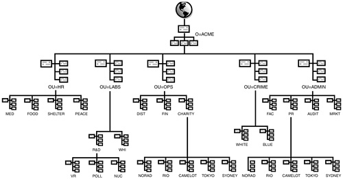
Examine Table 19.10 for a critical comparison of the two most popular tree-design approaches: geographic and functional.

Although your eDirectory tree might prove to be most efficient if you choose between the geographic, regional, or functional approaches, you aren’t required to choose only one. Some companies, in fact, require a combination of these approaches in the design of the top layers of their eDirectory trees.
This completes step 2: design the top layers. Yeah! We’re well on our way to completing ACME’s eDirectory tree design. There’s only one step left, and it involves thousands of resources. Good luck.
The bottom layers of the eDirectory tree should be designed according to the organizational boundaries of your company. In other words, the bottom Organizational Units should be built along the lines of company divisions, departments, and workgroups (see Figure 19.23).
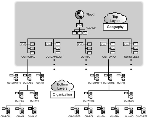
During the design of the bottom layers, you’ll need to ensure that there is a place for every user and network resource. Shared resources should be distributed near the users who need them. For example, ACME’s Charity and PR departments have an office in each major location. Each office has at least one server and shares information with a central database in CAMELOT. For this reason, we’ve decided to create an OU=CHARITY and OU=PR container in every location (see Figure 19.23).
When planning the design of the lower layers of your eDirectory tree, ask yourself the following questions:
![]() Will you use only your organization chart to determine the structure? What other resources could you use?
Will you use only your organization chart to determine the structure? What other resources could you use?
![]() Does your structure represent logical workgroups?
Does your structure represent logical workgroups?
![]() Are all groups included in a specific location?
Are all groups included in a specific location?
![]() Do any containers include groups that are in different locations?
Do any containers include groups that are in different locations?
![]() How are you including remote sites in the eDirectory tree?
How are you including remote sites in the eDirectory tree?
![]() Are all levels necessary?
Are all levels necessary?
![]() Are you following naming standards?
Are you following naming standards?
![]() How do users access network resources?
How do users access network resources?
![]() How will growth of the organization affect the eDirectory tree?
How will growth of the organization affect the eDirectory tree?
![]() How are applications going to be distributed?
How are applications going to be distributed?
![]() How will you account for traveling users or other users similarly spanning a large area?
How will you account for traveling users or other users similarly spanning a large area?
Resource placement considerations will also affect how you design the bottom layers of your directory tree. If network resources are organized according to workgroups, they should be placed in the same container where users have been placed. However, if network resources offer services to multiple departments, you should place the resources higher in the tree, possibly at the location-based OU container.
Congratulations!
You’re the proud owner of a new eDirectory tree design. Let’s review: pyramid, geography, organization—all done. Well, at least with the rough draft. Next, you should consider a few external design factors before finalizing the design. It’s time for some fine-tuning.
Test Objective Covered:
![]() Identify Fundamental Directory Design Factors (continued)
Identify Fundamental Directory Design Factors (continued)
After you’ve completed the eDirectory tree design, you’ll need to fine-tune it by using a variety of special eDirectory design considerations. Fortunately, these considerations affect only the bottom layers of the tree because they only have an effect on user accessibility and resources. The following is a list of the four most critical eDirectory tree design considerations:
![]() Administration—Affects the primary methods of network administration: centralized and/or decentralized
Administration—Affects the primary methods of network administration: centralized and/or decentralized
![]() Container size—Affects eDirectory partitioning, replication, fault tolerance, and synchronization traffic efficiency
Container size—Affects eDirectory partitioning, replication, fault tolerance, and synchronization traffic efficiency
![]() Login scripts—Affects user access to network resources
Login scripts—Affects user access to network resources
![]() Bindery services—Affects backward compatibility to NetWare 2 and NetWare 3 clients
Bindery services—Affects backward compatibility to NetWare 2 and NetWare 3 clients
Fortunately, the bottom layers of the tree represent the flexible half. Let’s explore these four external design pressures in a little more depth.
Tree administration is a key eDirectory design consideration because it affects how you and your distributed network administrators manage Directory objects, partitioning, time synchronization, and security.
To manage eDirectory effectively, Novell suggests that you consider the following two main types of network administration:
![]() Centralized—Relies on one or more information services (IS) Admin(s) for all portions of the eDirectory tree. The User object for this type of administrator is typically stored at the Organization level.
Centralized—Relies on one or more information services (IS) Admin(s) for all portions of the eDirectory tree. The User object for this type of administrator is typically stored at the Organization level.
![]() Decentralized—Distributes branch control to container administrators, typically at the functional or location OU level.
Decentralized—Distributes branch control to container administrators, typically at the functional or location OU level.
A centralized administration strategy depends on a single network administrator or IS group for management of eDirectory objects, partitioning, replication, and security. Central administrators (including Admin) are typically placed at the Organization level and must have Supervisor and Inheritable [SI] rights to the [Root] object.
If the eDirectory tree is to be managed centrally, the IS staff will build the entire tree and have control over all eDirectory objects. This approach helps standardize naming, simplifies object placement, and improves administrator navigation.
Another unique centralized administration strategy is to place all servers in a single eDirectory container (called the server container approach). The server container approach provides easier server access for users and simpler tracking of server activity. See Table 19.11 for a summary of the advantages and disadvantages of the server container centralized administration strategy.
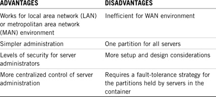
A decentralized administration strategy relies on various distributed individuals or groups who have managerial control over decentralized branches of the eDirectory tree. These individuals might be departmental administrators, or they might be responsible for all the network resources in a particular location.
If a department uses highly sensitive information and requires isolation from the rest of the organization, you could consider creating multiple trees or creating multiple organization objects.
In the decentralized administration model, you still need a centralized IS administrator to handle the top layers of the tree. However, you can block Admin from sensitive local information by placing an inherited rights filter (IRF) at the department or location level.
The next eDirectory design consideration involves container size and eDirectory partitioning. The total number of eDirectory objects in a container can negatively affect network performance if it rises to more than 3,500 objects. This is because very large containers are unwieldy to manage and can have an adverse effect on eDirectory partitioning and replication. (Note: This limitation applies only to eDirectory Version 7 and earlier. eDirectory Version 8 and later are much less susceptible to container sizing problems.) If a container has too many objects, you can split the container by creating additional containers.
For example, consider a university whose network consists of a LAN spanning a single campus, with a fiber-optic backbone between buildings. The eDirectory tree contains 37,500 User objects representing students, each of whom needs approximately the same access to resources. In this scenario, utilizing a single Organizational Unit with 37,500 User objects would be difficult to manage. It would also mean that all the objects would be in the same partition. A better strategy would be to consider using 5 to 10 functional OU containers for the User objects instead of just one.
It’s important to note that the number of objects in a given container can affect the effectiveness of Novell products that require the use of eDirectory, such as ZENworks, eDirectory for NT, and DNS/DHCP services.
Login scripts affect the bottom layers of the tree and indirectly control how users access certain eDirectory resources. In general, users need login scripts to map network drives, capture print queues, and set environmental variables.
Users who share login scripts should typically be grouped together in the same OU container. In this way, you can create a single container login script for all users with similar needs. Figure 19.24 shows two container login scripts: one for OU=FIN (shared by Guinevere and other users) and one for OU=DIST (shared by Merlin and other users). You should separate the users who need different login scripts for the same reason into groups. As you design the login scripts for your users, you are in fact designing the organizational structure for the bottom level of the tree.
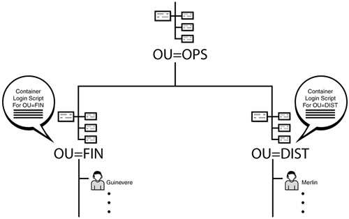
If a WAN link separates users who could use the same login script, you can create a user group at each end of the WAN link and then associate the two groups with the same login script. However, do not assign individual users to a login script across a WAN link.
Consider the following login script components as you organize users at the bottom layers of the eDirectory tree:
![]() Menus
Menus
![]() Applications
Applications
![]() Drive mappings
Drive mappings
![]() Printer capture statements
Printer capture statements
![]() Environment variable settings
Environment variable settings
Well, that’s all there is to it—not really! Remember, the glass is half full, and you’ve taken a huge gulp in this chapter. Use this information wisely as you expand the horizons of your network. Now, let’s continue our discussion of NetWare 6 eDirectory design and implementation features by learning how to implement this mysterious and exciting network directory...starting with accessibility!
See ya there!
In this exercise, you do the following:
![]() Part I: Review the Design Guidelines for the Upper Layers of an eDirectory Tree
Part I: Review the Design Guidelines for the Upper Layers of an eDirectory Tree
![]() Part II: Design the Upper Layers of the ACME eDirectory Tree
Part II: Design the Upper Layers of the ACME eDirectory Tree
Mention the rules and guidelines you adopted.
Complete the following questions to prepare for designing the upper layers of the ACME eDirectory tree:
![]() Why should you design an eDirectory tree like a pyramid?
Why should you design an eDirectory tree like a pyramid?
![]() Why do eDirectory trees need unique names?
Why do eDirectory trees need unique names?
![]() When would you create Organizational Unit objects based on location?
When would you create Organizational Unit objects based on location?
![]() When would you consider using organizational units representing regions?
When would you consider using organizational units representing regions?
![]() When would you create Organizational Unit objects based on function?
When would you create Organizational Unit objects based on function?
Draw the upper layers of an eDirectory tree design for the entire ACME company. Include the tree name, organization object, and first-level organizational unit objects. Use the following as reference material:
![]() The ACME profile and organizational chart from Chapter 18
The ACME profile and organizational chart from Chapter 18
![]() Object naming standards from the tables you built in Lab Exercise 19.2
Object naming standards from the tables you built in Lab Exercise 19.2
In this exercise, you review the guidelines for designing the lower layers of an eDirectory tree by answering a few questions. You then design the complete eDirectory tree for the ACME organization.
Specifically, you do the following:
![]() Part I: Review the Design Guidelines for the Lower Layers of an eDirectory Tree
Part I: Review the Design Guidelines for the Lower Layers of an eDirectory Tree
![]() Part II: Design the Complete ACME eDirectory Tree
Part II: Design the Complete ACME eDirectory Tree
Complete the following questions about designing the lower layers of the eDirectory tree:
![]() Why do the lower layers of a tree reflect the corporate structure, and how do they provide better user access to network resources?
Why do the lower layers of a tree reflect the corporate structure, and how do they provide better user access to network resources?
![]() How does eDirectory tree design affect whether you use centralized or decentralized administration?
How does eDirectory tree design affect whether you use centralized or decentralized administration?
![]() Relative to future growth, how does an eDirectory tree design affect container size?
Relative to future growth, how does an eDirectory tree design affect container size?
To effectively design and draw the lower layers of the eDirectory tree, you must draw the structure of the complete tree, including both upper and lower layers.
Draw the structure of your tree design showing the top layers and lower layers for ACME. Use the following as reference material:
![]() Your upper-layer eDirectory tree structure from Lab Exercise 19.3
Your upper-layer eDirectory tree structure from Lab Exercise 19.3
![]() The ACME profile and organizational chart from Chapter 18
The ACME profile and organizational chart from Chapter 18
![]() Object naming standards from the tables you built in Lab Exercise 19.2
Object naming standards from the tables you built in Lab Exercise 19.2
Draw a detailed view of the CAMELOT site at ACME and include all organizational unit objects (OU=) for the division, user objects (CN=) for all employees in the organizational chart, and server objects (CN=) for the servers at the CAMELOT site.