Identifying Models
In Figure 10.35, there are several CDMs open in the Browser, and there are four diagram tabs in the canvas. One of the tabs is highlighted – this is the diagram we can see on the canvas. The name of the diagram is ‘Diagram_1’, but which model is it from?
Figure 10.35 Which diagram is which?
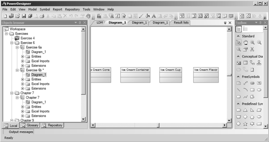
Before working on the diagram or accessing the menus, you need to be sure which model you’re working in. There are several ways you can identify the model:
· Hover the mouse over the diagram tab, and a tooltip will appear. The tooltip will display the following information: Model Type, Model Name:Package Name (if relevant), Diagram Name, and the model path and filename.
· Right-click one of the entity symbols and select ‘Find in Browser’ from the contextual menu
· Right-click a blank area of the diagram and select ‘Properties’ from the Contextual menu – this opens the property sheet for the model
· Add a title box to the diagram (using the ‘Title’ tool on the ‘Free Symbols’ palette) – Figure 10.36 shows an example.
Figure 10.36 A diagram title box
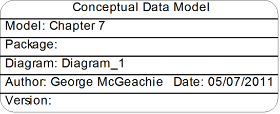
 If you double-click a title box, the model’s property sheet will open.
The best way to distinguish your diagrams from each other is to give them a meaningful name, such as Contact Subject Area - Fully Attributed.
Changing the Default Diagram
Every model has a default diagram, which automatically opens when you open the model. Initially, this will be the diagram created for you by PowerDesigner when the model was created.
If your model has several diagrams, you can choose a different default diagram in three ways:
· Open the property sheet for the model, and change the ‘Default Diagram’ at the bottom of the ‘General’ tab
o See ‘Many Ways of Doing Things’ to discover the many different ways you can access the model’s property sheet
· Open the property sheet for the preferred default diagram, and then select ‘Default Diagram’ at the bottom of the ‘General’ tab
· Right-click the name of the diagram in the Browser, and select Set as Default.
The default diagram can be a Dependency Matrix.
Getting Ready To Print
By default, the Canvas shows vertical and horizontal lines in the background; these are the boundaries of the printed pages. The default orientation is portrait, and that doesn’t suit every diagram. On the File menu, the Page Setup option allows you to change the diagram orientation, specify margins, and decide which information to include on printed pages. The <Apply To> button allows you to change the settings on several diagrams at the same time.
Once the page orientation is suitable, you can use the Fit to Page option on the Symbol menu to choose the way in which the diagram fits on the printed page. If the diagram is small enough, you can force it to fit onto a single page, using the options shown in Figure 10.37.
Figure 10.37 Fit to page

You can also use the ‘Fit to Page’ button  on the Layout toolbar.
 After you ‘Fit to Page’, the cursor reverts to the last Toolbox tool you selected, such as drawing entities. Click the right mouse button to unset it.
Printing a Diagram
You can print the currently selected diagram at any time. You can print the whole diagram, a selection of pages, or a selection of objects.
- [optional] Select certain symbols in the diagram in order to print them and exclude the others.
- Select File|Print or click the Print tool to open the Print Diagram dialog (see Figure 10.38), which displays default print options and the number of printed pages needed for the diagram.
Figure 10.38 Diagram print options

3. [optional] Specify the pages to print in the Page range groupbox or by clicking in the Preview pane. Only pages with an overlaid page frame will be printed.
4. [optional] Specify a page scale or set of pages to fit. By default, diagrams are printed at 100% scale on as many pages as necessary.
5. [optional] Click the <Page Setup> button to open the Page Setup dialog and specify your page layout.
This allows you to alter the Page Setup for this print operation only. If you want to permanently change the Page Setup for the diagram, exit the Diagram print dialog, and access ‘Page Setup’ on the ‘File’ menu. See “Getting Ready To Print”, earlier in this chapter.
6. Click OK to start printing.
When you print a diagram, you do not print detailed information about the model objects. To do this, you need to create a model report.
![]() “Printing Diagrams” (Core Features Guide)
“Printing Diagrams” (Core Features Guide)
Deleting a Diagram
When you delete a diagram, you delete a view of a model or a package. This action does not affect the objects in the model or package. You cannot delete the last diagram in a model or package.
You can delete a diagram in any of the following ways:
· Select the diagram node in the Browser and press the <Del> key.
· Right-click the diagram window background and select Diagram|Delete from the contextual menu.
· Select View|Diagram|Delete.
![]() “Deleting a Diagram” (Core Features Guide)
“Deleting a Diagram” (Core Features Guide)
Working with Symbols
 This section explains how to work with diagram symbols.
Creating and Drawing Symbols
PowerDesigner allows you to create symbols in several ways. The usual way is to draw new symbols and objects using the tools in the Toolbox (see “The Toolbox” earlier in this chapter). You can also create symbols by dragging objects from the Browser, copying and pasting existing symbols, and by creating a new diagram from an existing selection.
![]() “Creating Objects from the Toolbox” (Core Features Guide)
“Creating Objects from the Toolbox” (Core Features Guide)![]() “Copying and Pasting Objects” (Core Features Guide)
“Copying and Pasting Objects” (Core Features Guide)![]() “Dragging and Dropping Objects” (Core Features Guide)
“Dragging and Dropping Objects” (Core Features Guide)
Automatic Link Routing
PowerDesigner allows you to take complete control of the routing of your Link Symbols, and also offers to help manage the routing for you. To allow PowerDesigner to route your lines, ensure that your default corner style has right-angled corners, and select ‘Automatic Link Routing’ in the Display Preferences. It is also useful to select ‘Show bridges at intersections’ as well. See “Display Preferences for Relationships” in Chapter 13, to find out about the different line styles.
If ‘Automatic Link Routing’ is enabled in your diagram, then PowerDesigner decides on the route for any new link symbols you draw. If necessary, it will move other links and stretch symbols to accommodate the new link.
PowerDesigner doesn’t take over completely - you’re free to move the link yourself after PowerDesigner has routed it. See “Rerouting Link Symbols Manually” and “Bending and Straightening Link Symbols”, later in this chapter.
Once you’ve manually moved a link, your preference overrides the algorithm, and the link is no longer controlled by auto-routing. By selecting the link, right-clicking it, and selecting reroute link, you make it subject again to auto-routing, your change is discarded, and the link is rerouted optimally according to the algorithm. If you don’t like the result, remember ‘Undo’.
Selecting, Editing, and Resizing Symbols
You can select symbols in a PowerDesigner diagram using standard Windows gestures. You can edit properties of the selected symbol's object or its sub-objects, or resize the symbol by clicking and dragging on its handles.
In Chapter 11, you’ll see that you can select the ‘Edit in place after creation’ General option, to have the name of each object that you create immediately selected for editing.
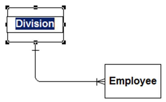
To select a symbol, select the default Pointer tool  from the standard palette, and click on the symbol. In the following example, the Division entity is selected, and can be moved by dragging the center of the symbol, or resized by dragging on one of its handles (the black boxes on the corners and along the sides), as shown in Figure 10.39.
Figure 10.39 An entity’s handles

Note: To resize all the symbols in a diagram at once, click the Grabber tool  and drag one of the handles.
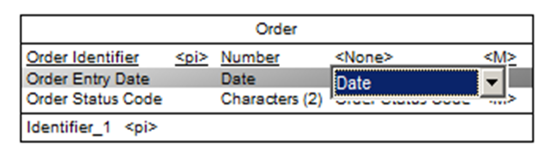
Once a symbol is selected, clicking on one of its object properties lets you edit its value. In Figure 10.40, the entity name is selected for editing.
Figure 10.40 Editing the entity name
Once a symbol has been selected, you can also edit the name of a displayed sub-object by clicking on the name, as shown in Figure 10.41.
Figure 10.41 Editing a sub-object name

Once a sub-object is selected, you can move among its editable properties by pressing the <Tab> key. You can also move up and down the list of sub-objects using the arrow keys, as shown in Figure 10.42.
Figure 10.42 Editing further properties
To open the property sheet for a sub-object, select it, and then double-click the highlighted entry (shown shaded gray in the figures above).
To select all the symbols in an area, click on the Canvas, hold down the mouse button, and drag the mouse. As you move the mouse, a selection box appears on the screen. When you release the mouse button, any symbol that lies completely inside the box will be included in the selection. The word completely is important – for a symbol to be included in the selection, all of the symbol’s handles must be inside the box. For example, see the selection box shown as a dotted line in Figure 10.43. When the mouse button was released, the entities Ice Cream Container, Order, and the shortcut to Division were selected as shown in Figure 10.44; the Division and Employee entities and the relationship were not selected, as at least one of their handles was outside the selection box.
Figure 10.43 A selection box
| Figure 10.44 The resulting selection
|


To include them in the selection, just hold down <Shift> and click on each symbol. Repeat the action to remove them from the selection.
Here’s another trick for selecting multiple related objects – select any symbol, click the right mouse button, select Edit, and then select Select Connected Symbols. The same option is also available on the Edit menu. This also works if you have more than one object selected. Don’t forget to use <Shift> and click to fine tune the selection, if you need to.
If you want to carry out a lot of actions on a set of selected symbols, use the Group Symbols command on the Symbols menu to make sure they’re treated as a set. Ungroup them when you’ve finished.
Rerouting Link Symbols Manually
Whether or not you use auto-routing, you are able to exercise control over the positioning of individual relationships and groups of relationships.
The contextual (right-click) menu gives you a number of options for altering the layout of selected relationships. We have seen some of these before, so we do not describe them here – see “Contextual Menus”, earlier in this chapter. Table 10.8 lists the remaining options.
Table 10.8 Relationship contextual menu options
Option | Description |
|---|---|
Detail | Opens the Relationship property sheet. |
Change to Entity | Runs a wizard to convert the relationship into an associative entity and two relationships. |
Spell Check | Check the spelling in the relationship properties. |
Related Diagram | Open or create a ‘related diagram’. To create a link from an object to an existing diagram, do so via the ‘Related Diagrams’ tab on the property sheet. |
Reroute Link | Re-applies automatic routing to the relationship. |
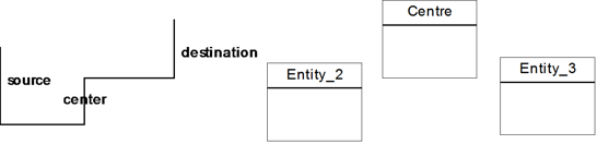
Disposition | Automatically arranges selected symbols in the diagram. There are various forms of disposition: · Horizontal <Ctrl+H> – where possible, removes corners from selected link objects and converts them into horizontal lines. · Vertical <Ctrl+L> - where possible, removes corners from selected link objects and converts them into vertical lines. · Flip Horizontal – flips the selected symbols through the horizontal center of the group. Where appropriate, the orientation of an individual symbol may also be changed. For example, here is a line and three entities before applying ‘Flip Horizontal’:
and after:
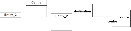
· Flip Vertical - flips the selected symbols through the vertical center of the group. Where appropriate, the orientation of an individual symbol may also be changed. For example, here is a line and three entities before applying ‘Flip Vertical’:
and after:
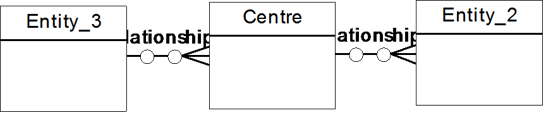
· Arrange Symbols – distributes the selected symbols evenly, both horizontally and vertically. For example, the following entities and relationships would be re-arranged, from this:
to this:
Now apply the Horizontal Disposition to the relationships in this example, to create the following:
· Arrange Connectors – straightens the selected link symbols and centers their endpoints in the objects that they connect.
· Arrange Attach Points - centers the endpoints of the selected link symbols in the objects that they connect. · Arrange Attached Text – returns text objects associated with the selected link symbols to their default position. |
Order | Promotes or demotes the selected symbols in terms of layers within the diagram. This can be useful when you have overlapping symbols and want to have one appear above the other. The following options are available: · Bring to Front · Send to Back · Bring Forward · Send Backward By default, when you insert a free symbol (for example, a note) on a model object symbol (for example, a table), the free symbol is always inserted behind object symbols. Priority is given to the front-most symbols. When symbols overlap, it may not be possible to select the symbol in the background, even if its handles are visible. |