CHAPTER 11
How do I create entities in PowerDesigner?
Draw, import, refine
Relationships add the lines
Attributes, detail
In this chapter, we will show you how to create a simple data model with six entities, shown in Table 11.1. Make sure you understand the content of Chapter 10 before you start.
Table 11.1 Our six entities
Entity Name | Definition |
Ice Cream Cone | An edible container which can hold one or more ice cream scoops. |
Ice Cream Container | A holder of ice cream that is either edible, in the case of an ice cream cone, or recyclable, in the case of an ice cream cup. |
Ice Cream Cup | A recyclable container that can hold one or more ice cream scoops. |
Ice Cream Flavor | The distinctive taste of one ice cream product over another. Flavors are recognized and selected by consumers. Examples include Chocolate, Vanilla, and Strawberry. |
Ice Cream Theme | A group of ice cream flavors that share at least one common property. For example, the Brownie Ice Cream and Cake Batter Ice Cream flavors are grouped into the Cake Ice Cream Theme. |
Order | Also known as an ice cream sale, an order is when a consumer purchases one or more of our products in a single visit to our ice cream store. |
There are three main methods for creating entities: drawing them on a diagram, adding them via the Browser, and adding them via object lists.
Drawing New Entities
 You’ll probably create most new entities by drawing them on a diagram. To add any type of symbol on a diagram, you have to click on a tool in the Toolbox. Objects, such as Entities or Tables, can be created independently in any free space in the diagram, while links, such as relationships, are drawn as connections between existing objects.
To create a new Entity in a Conceptual Data Model, click on the  tool in the Conceptual Diagram palette in the Toolbox. You’ll notice that the cursor shape has changed from a pointer to the entity icon . If the icon is not available on the Toolbox, then your current diagram is not a Conceptual Diagram. You can bring the Conceptual Diagram to the front by clicking on the diagram’s tab.
While the cursor displays the entity icon, you can click anywhere on the Canvas, and a new entity symbol will appear. Each time you click, another entity appears. To start creating a different type of object or symbol, click on another Toolbar tool. To stop drawing entities, simply right-click anywhere, or re-select the Pointer tool from the Standard palette. To revert to a previously selected tool, hold down <Ctrl> and perform a double right-click.
The default names for new entities will be ‘Entity_nn’. The value of ‘nn’ will depend on the names of existing entities. If you prefer to edit the entity name as soon as you draw one, you can do that by selecting ‘Edit in place after creation’ in the first tab of the General Options. Now, you are offered the chance to edit the name of each entity after you’ve added it. When you have finished editing, just click again to create the next entity.
YOUR TURN TO PLAY
Open the workspace you created in Exercise 8, and create a new top-level folder called ‘Chapter 11’. Now create a new Conceptual Data Model by clicking on the ‘New Model’ option on the ‘File’ menu. Call the model ‘Chapter 11’. As soon as you’ve created the model, press <Ctrl+S> to save it in the ‘Exercises’ folder. You should have ‘Diagram_1’ open on the Canvas. Rename the diagram to ‘Chapter 11 CDM’.
Open the ‘General Options’ on the Tools menu, select ‘Edit in place after creation’, then click on <OK>. Now click on the button in the Toolbox, and then click on the Canvas, edit the entity name, and repeat for the other two entities. Use the first three entity names shown in Table 11.1. When you have finished adding entities, click the right mouse button, then save the diagram again.
The appearance of the entity symbols will depend on the default display preferences in your model. By default, they will probably start out looking like Figure 11.1, assuming you are using the ‘Entity/Relationship’ notation.
Figure 11.1 Default entity symbol

This symbol has three compartments. The entity name is always in the top compartment, never outside the symbol. The other compartments display two of the entity’s properties, which are blank because those properties are not defined. The format and content of the symbol are determined by the diagram Display Preferences, described later in this chapter.
Changing Model Notation
If your entity symbols don’t look the way you expect, you may need to change the Model notation via the Model Options. For example, rounded corners on all entity symbols are a sign that the notation is ‘Barker’. See Chapter 9 for more information.
Creating Entities in the Browser
In Exercise 8, you created new entities by copying them in the Browser. Of course, you can also create new entities from scratch in the Browser; in fact you can create any object in the Browser. The following instructions will work for any type of object.
1. Right-click the location in the Browser where you want to create the entity. If you right-click the name of a model or package, select New, and then Entity, to open a new default property sheet. You can also right-click the Entities folder in the Browser, and then select New.
2. Type an object name in the ‘General’ tab of the property sheet, and then add any other relevant properties in the remaining fields of this or the other tabs. Note that PowerDesigner updates the entity code for you, if Name to code mirroring is enabled, which is the default setting in the Model Options.
3. Click OK to confirm the creation of the entity. The entity is now listed under the heading ‘Entities’, and its symbol has been added to the current diagram.
YOUR TURN TO PLAY
Follow the instructions above to create the remaining entities from Table 11.1. You should now have three entities on your diagram, and six in the Browser.
Editing via the List of Entities
YOUR TURN TO PLAY
- Right-click the model name in the Browser, select List of and then Entities. The list of entities will open.
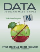
- Click on the ‘Customize’ tool to customize the columns; refer to Figure 10.30 if you need help to find the tool. In the list of columns, uncheck ‘Code’ and check ‘Description’ (not ‘Description Text’), then click <OK>.
3. Next click on the ‘Description’ cell for one of the entities, and then click on the ellipsis button that appears to the right.
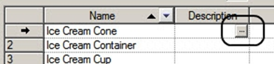
4. Now you can type in the entity description from Table 11.1. Use the formatting tools shown in Figure 11.2 to change the font and style, if you want. Click <OK> when you’re finished, then click on <Apply> to save the changes.
Figure 11.2 Editing a description
5. To edit the next description, take a different approach. In the list of entities, double-click the row number for another entity to open the property sheet for the Entity. Select the ‘Notes’ tab, and then type the description. If you have Microsoft Word installed, click on the ‘Edit with …’ button on the toolbar above the description, and Microsoft Word will start up. You will probably have to confirm that the document is in RTF format. Try pasting text or images from the clipboard into the description. When you close Word, the description will update in PowerDesigner.
6. When you have finished entering descriptions, click on <OK> to close the object list and save any changes you have not previously applied. Now make sure that all your entities are on the diagram. Use the ‘Show Symbols’ feature we showed you in Chapter 10.
7. Right-click any data model diagram that displays entities, then select Display Preferences from the contextual menu. In the ‘Display Preferences’ window, select ‘Entity’ on the left, then select the ‘Format’ tab. As you can see from Figure 11.3, the ‘Format’ tab shows the current default and format for entity symbols in the current diagram. Including the name, there are five possible compartments – the number and layout of the compartments depends on the properties selected for display.
This shows you how and where the available properties will be displayed, if you choose to display them. To change the formatting, click on <Modify>, and the Symbol Format dialog will be displayed. Make some changes to the entity format, such as altering the shadow style and the font used for the entity name, then click <OK>. Your changes will be reflected in the sample symbol shown in the ‘Format’ tab. Now you can commit the changes to your symbols, use the settings to reset the defaults, or choose the diagrams to apply the preferences to, as discussed in the previous section.
Figure 11.3 Default symbol format

Exporting the Diagram Image
PowerDesigner provides an easy way of saving your diagram as an image file, in either color or monochrome. Just select the symbols you want to export, click on the Edit menu, select Export Image, and then choose the file location, name, and format. For color exports, select Export in Color on the Edit menu first.
Object Property Sheets
We first looked at property sheets in Chapter 10. They are a powerful feature of PowerDesigner, and their contents vary depending on the type of object, so we will continue to introduce them to you gradually.
Before we look at the content of these tabs, let’s look at some of the options we have regarding property sheets. You’ll remember that we told you about ‘Favorite’ tabs in Chapter 10, and showed you some of the tabs.
You have control over several aspects of how PowerDesigner handles the display of property sheets via the ‘Dialog’ section of General Options, available on the Tools menu. The ringed options in Figure 11.4 are particularly useful.
Figure 11.4 General options - dialog

| “Dialog Box General Options” (Core Features Guide) |
The following two figures show the content of two of the tabs for an entity. All of the standard Entity tabs are visible in both figures.
There is a difference between the ‘General’ tab in Figure 10.17 and that in Figure 11.5 – there is a new property called Plural name, which was added when a model extension was loaded. You can find out more about this model extension in Chapter 13: look for the section on Assertion Statements.
The ‘Traceability Links’ tab in Figure 11.6 shows a traceability link that was drawn on a diagram. Double-clicking the entry would open the property sheet for the linked object, in this case the ‘Lecturer’ entity.
Importing Entities from Excel Files
Entities and other objects can be imported and updated from Excel workbooks. See “Excel Import” in Chapter 21 for more information.
Figure 11.5 The entity ‘Thesis’ – General tab

Figure 11.6 The entity ‘Thesis’ – ‘Traceability Links’ tab

EXERCISE 9: Creating LDM Entities in PowerDesigner
Within the ‘Exercises’ workspace you created in Exercise 8, create a folder called ‘Exercise 9’. In the folder, create a LDM called ‘Exercise 9a’.
Create six entities in the new model, using the information in Table 11.2. Experiment with the content and style of the entity symbols. Entities marked with ‘*’ can be copied from the ‘Chapter 11’ CDM.
Table 11.2 Our six entities
Entity Name | Definition |
Color * | A primary color within the spectrum of visible light. |
Ice Cream Cone | An edible container that can hold one or more ice cream scoops. |
Ice Cream Container * | A holder of ice cream that is either edible, in the case of an ice cream cone, or recyclable, in the case of an ice cream cup. |
Ice Cream Cup * | A recyclable container that can hold one or more ice cream scoops. |
Order * | Also known as an ice cream sale, an order is when a consumer purchases one or more of our products in a single visit to our ice cream store. |
Order Line | A product purchased during a single visit to our ice cream store. |
Customize the view of a list of entities – ensure that you include at least the following properties: Name, Modification Date, Generate, and Description. Use the ‘Export to Excel’ tool to export the entities to Excel. Keep this file – you will need it in Chapter 21.
Key Points · Use the Description property for descriptions, rather than the Comment property. · Entities can be created by drawing them on a diagram, adding them via the Browser, or adding them via object lists. · Make use of existing documentation using the Excel Import wizard. · Object lists provide a complete editing environment. · It's easy to export the diagram as an image file. |