
CHAPTER 5
What are relationships?
Rules all around us
Relationships tell the tale
Connecting the dots
This chapter defines rules and relationships and the three different levels at which relationships can exist: subject area, logical, and physical. Data rules are distinguished from action rules. Cardinality and labels are explained so that you can read any data model as easily as reading a book. Other types of relationships, such as recursive relationships and subtyping, are discussed, as well.
Relationship Explained
In its most general sense, a rule is an instruction about how to behave in a specific situation. The following are familiar examples of rules:
· You must clean your room before you can go outside and play.
· If you get three strikes, you are out and it is the next batter’s turn.
· The speed limit is 80 km/h (or 55 mph).
Many such rules can be visually captured on our data model through relationships. A relationship is displayed as a line connecting two entities. It captures the rules between these two entities. If the two entities are Employee and Department, the relationship may capture the rules “Each Employee must work for one Department” and “Each Department may contain many Employees.”
Relationship Types
A rule can be either a data rule or an action rule. Data rules are instructions on how data relate to one another. Action rules are instructions on what to do when data elements contain certain values. Let’s talk about data rules first. There are two types of data rules - structural and referential integrity (RI) data rules. Structural rules (also known as cardinality rules) define the quantity of each entity instance that can participate in a relationship. For example:
· Each product can appear on one or many order lines.
· Each order line must contain one and only one product.
· Each student must have a unique student number.
Referential Integrity rules focus on ensuring valid values:
· An order line cannot exist without a valid product.
· A claim cannot exist without a valid policy.
· A student cannot exist without a valid student number.
When we define a structural rule, we get the corresponding RI rule for free. For example, if we define this structural rule on our data model, “Each order line must contain one and only one product”, it is automatically assumed and included that “An order line cannot exist without a valid product.”
Action rules, on the other hand, are instructions on what to do when data elements contain certain values:
· Freshman students can register for at most 18 credits a semester.
· A policy must have at least three claims against it to be considered high-risk.
· Take 10% off an order if the order contains more than five products.
In our data models, we can represent the data and enforce data rules, but we cannot enforce action rules: the actions resulting from these rules would be within the scope of a process model, not a data model. A student data model can capture the level of student, such as Freshman or Senior, as well as the number of credits each student is taking each semester, but cannot enforce that a freshman student register for no more than 18 credits a semester.
Returning to our ice cream example, I eventually ordered a double scoop of gelato in a cone - one scoop of Chocolate and one scoop of Banana. Many relationships can describe the process of placing this order, such as:
· An ice cream container can be either a cone or a cup.
· Each ice cream container can contain many scoops of ice cream.
· Each ice cream scoop must reside in an ice cream container (or our hands would get really sticky holding that scoop of banana gelato).
· Each ice cream flavor can be chosen for one or many ice cream containers.
· Each ice cream container can contain many flavors.
The three levels of granularity that apply to entities and data elements, also apply to the relationships that connect entities. Subject area relationships are high level rules that connect key concepts. Logical relationships are more specific and enforce the rules between the logical entities. Physical relationships are also specific rules and apply to the physical entities that the relationship connects. These physical relationships eventually become database constraints, which ensure that data adheres to the rules. Therefore, in our ice cream example, “Each ice cream container can contain many scoops of ice cream”, can be a subject area relationship. This high-level rule can be broken down into more detailed, logical relationships, such as defining the rule on the different types of containers: “An ice cream container can be either a cone or a cup.” This logical relationship then translates into the physical relationship “An ice cream container must be of one ice cream container type, whose values are ‘cone’, ‘cup’, and ‘not applicable’.”
Cardinality Explained
Cardinality defines the number of instances of each entity that can participate in a relationship. It is represented by the symbols that appear on both ends of a relationship line. It is through cardinality that the data rules are specified and enforced. Without cardinality, the most we can say about a relationship is that two entities are connected in some way through a rule. For example, Person and Company have some kind of relationship, but we don’t know much more than this.
The domain of values to choose from to represent cardinality on a relationship is limited to three values: zero, one, or many. Many (some people read it as more), means any number greater than one. Each side of a relationship can have any combination of zero, one, or many. Specifying zero or one allows us to capture whether or not an entity instance is “required” in a relationship. Specifying one or many allows us to capture “how many” of a particular instance participates in a given relationship.
Because we have only three cardinality symbols, we can’t specify an exact number (other than through documentation), as in “A car has four tires.” We can only say, “A car has many tires.”
 In PowerDesigner, we can record this information against the relationship, and display it on diagrams.
A data model represents something in the real world. In capturing this something, there is always a tradeoff between refinement and simplicity. The greater the variety of symbols we show on a model, the more we can communicate. But more symbols also means greater complexity. Data modeling (using the notation in this book), forfeits a certain amount of refinement for simplicity. The advantage is we can explain very complex ideas with a simple set of symbols. In fact, I taught my six-year-old cardinality and she can now read the business rules on a data model. She is the only person in her Kindergarten class who can read cardinality (I am so proud!).
Each of the cardinality symbols is illustrated in the following example of Ice Cream Flavor and Ice Cream Scoop. An ice cream flavor is a selection choice for an ice cream scoop. An ice cream scoop must be one of the available ice cream flavors. Formalizing the rules between flavor and scoop, we have:
· Each Ice Cream Flavor can be the selection choice for one or many Ice Cream Scoops.
· Each Ice Cream Scoop must contain one Ice Cream Flavor.
Figure 5.1 captures these business rules.
Figure 5.1 Ice Cream Flavor and Ice Cream Scoop, take 1
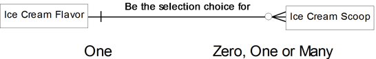
The small vertical line means “one.” The circle means “zero.” The triangle with a line through the middle means “many.” Some people call the “many” symbol a crow’s foot. Relationship lines are frequently labeled to clarify the relationship and express the rule that the relationship represents. Thus, the label “Be the selection choice for” on the line in this example, helps in reading the relationship and understanding the rule.
Having a zero in the cardinality makes us use optional-sounding words such as ‘may’ or ‘can’ when reading the relationship. Without the zero, we use mandatory-sounding terms such as ‘must’ or ‘have to’. So instead of being redundant and saying:
· Each Ice Cream Flavor may be the selection choice for zero, one or many Ice Cream Scoops.
We take out the word ‘zero’ because it is expressed using the word ‘can’, which implies the zero:
· Each Ice Cream Flavor may be the selection choice for one or many Ice Cream Scoops.
Every relationship has a parent and a child. The parent entity appears on the “one” side of the relationship, and the child appears on the “many” side of the relationship. In Figure 5.1, the parent entity is ‘Ice Cream Flavor’, and the child entity is ‘Ice Cream Scoop’. When I read a relationship, I always start with the entity on the “one” side of the relationship (the parent entity) first. “Each Ice Cream Flavor can be the selection choice for one or many Ice Cream Scoops.” It’s then followed by reading the relationship from the many side: “Each Ice Cream Scoop must contain one and only one Ice Cream Flavor.” In truth, it doesn’t matter which side you start from, as long as you are consistent. In Chapter 13 we’ll see how PowerDesigner makes things easy for you with relationship role names.
I also always use the word ‘each’ in reading a relationship, starting with the parent side. The reason for the word ‘each’ is that you want to specify, on average how many instances of one entity relate to a different entity instance. ‘Each’ is a more user-friendly term to me than ‘A’.
Fortunately, PowerDesigner also uses the word ‘Each’ within these phrases, which they call “Assertion Statements”.
Let’s change the cardinality slightly and see how this impacts the resulting business rule. Assume that because of the rough economy, this ice cream shop decides to allow consumers to select more than one flavor in a scoop. Figure 5.2 contains the updated cardinality.
Figure 5.2 Ice Cream Flavor and Ice Cream Scoop, take 2

This is known as a many-to-many relationship, in contrast to the previous example, which was a one-to-many relationship. The business rules here read as follows:
“Each Ice Cream Flavor must be the selection choice for one or many Ice Cream Scoops.”
“Each Ice Cream Scoop must contain one or many Ice Cream Flavors.”
Note the use of the word ‘must’ – the relationship is mandatory – there must be at least one child entity in each relationship.
Make sure the labels on relationship lines are as descriptive as possible. Here are some examples of good label names:
· contain
· work for
· own
· initiate
· categorize
· apply to
Always avoid the following words as label names, as they provide no additional information to the reader (you can use these words in combination with other words to make a meaningful label name; just avoid using these words by themselves):
· has
· have
· associate
· participate
· relate
· be
A useful technique for checking whether relationship names make sense is to read them out aloud to a colleague who’s not directly involved in creating the model. If they don’t understand what you mean, you may need to reconsider your choice of verb. For example, replace the relationship sentence:
A Person is associated with one Company.
with
A Person is employed by one Company.
Many modelers capture labels on both sides of the relationship line, instead of just one side, as shown in this chapter. In weighing simplicity versus precision, I chose simplicity. The other label can often be inferred from the label that appears on the model. For example, I assumed the label ‘contain’ in Figure 5.1 and read the rule from Ice Cream Scoop to Ice Cream Flavor this way: “Each Ice Cream Scoop must contain one Ice Cream Flavor.”
Ron Ross (Ross, 2009, pp. 74, 77) makes some useful points regarding the role of verbs in describing facts. There are too many to repeat here, so we suggest you read his book to find out more.
Recursion Explained
A recursive relationship is a rule that exists between instances of the same entity. A one-to-many recursive relationship describes a hierarchy, whereas a many-to-many relationship describes a network. In a hierarchy, an entity instance has at most one parent. In a network, an entity instance can have more than one parent. PowerDesigner supports recursive relationships, but refers to them as ‘reflexive’ relationships; in this book, we’ll use the word ‘recursive’ when discussing the concept, and ‘reflexive’ when discussing PowerDesigner specifically.
Let’s illustrate both types of recursive relationships using Employee. See Figure 5.3 for a one-to-many recursive example and Figure 5.4 for a many-to-many example.
Figure 5.3 An Employee can work for one Manager

 The two statements starting with ‘Each Employee’ were created by PowerDesigner, from the two role names given to the relationship. Without these role names, the statements would read:
“Each Employee may have one or more other Employee”
“Each Employee may have at most one other Employee”.
These are known as ‘Assertion’ statements in PowerDesigner. You can see how much more meaningful the statements are in Figure 5.3, where the phrases ‘manage’ and ‘be managed by’ replace the default word ‘have’.
Using sample values such as ‘Bob’ and ‘Jill’ and sketching a hierarchy or network can really help understand, and therefore validate, cardinality. In Figure 5.3, for example, where the one-to-many captures a hierarchy, each employee has at most one manager. Yet in Figure 5.4 where the many-to-many captures a network, each employee must have many managers, such as Jane working for Bob, Jill, Ken, and Sven. (I would definitely update my resume if I were Jane.)
Figure 5.4 An Employee must work for many Managers
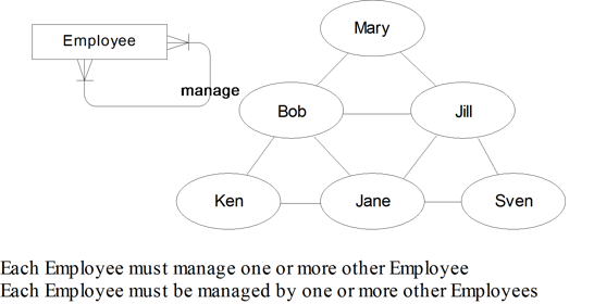
It is interesting to note that in Figure 5.3, there is optionality on both sides of the relationship. In this example, it implies we can have an Employee who has no boss (such as Mary) and an Employee who is not a manager (such as Ken, Jane, and Sven).
If you think about it, it makes sense for a recursive relationship to be optional; every hierarchy has to end somewhere – in the above example, Mary does not have a manager. If the relationship was mandatory, we would have to link Mary to another ‘managing’ employee, and that ‘managing’ employee would have to have a manager – where would we stop? We would have to create one or more dummy employees to implement the relationships, and this is definitely something we must avoid, if we value the quality of our data at all. Of course, this means that the mandatory recursive relationship shown in Figure 5.4 is invalid.
Data modelers have a love-hate relationship with recursion. On the one hand, recursion makes modeling a complex business idea very easy and leads to a very flexible modeling structure. We can have any number of levels in an organization hierarchy in Figure 5.3, for example. On the other hand, some consider using recursion to be taking the easy way out of a difficult modeling situation. There are many rules that can be obscured by recursion. For example, where is the Regional Management Level in Figure 5.4? It is hidden somewhere in the recursive relationship. Those in favor of recursion argue that you may not be aware of all the rules and that recursion protects you from having an incomplete model. The recursion adds a level of flexibility that ensures that any rules not previously considered are also handled by the model. It is therefore wise to consider recursion on a case-by-case basis, weighing obscurity against flexibility.
Relationship Descriptions
Many data modeling tools allow you to add a description to a relationship. In the majority of cases, the information provided by the relationship labels and cardinalities is sufficient to describe the rule, so the Description property is not required. Sometimes, however, you need to provide more information, perhaps regarding the circumstances that would cause the relationship to be created, in order for readers and users of the model to completely understand the relationship.
 If you need to provide more information, remember that every PowerDesigner object has a Description property. Alternatively, you can document the information as a Business Rule, and link it to the relationship.
Subtyping Explained
Subtyping groups the common data elements and relationships of entities, while retaining what is unique within each entity. Subtyping is an excellent way of communicating that certain concepts are very similar.
In our ice cream example, we are told that an ice cream cone and ice cream cup can each contain many scoops of ice cream, as illustrated in Figure 5.5.
Figure 5.5 Ice cream example before subtyping

· Each Ice Cream Cone may hold one or many Ice Cream Scoops.
· Each Ice Cream Scoop must be held in one and only one Ice Cream Cone.
· Each Ice Cream Cup may hold one or many Ice Cream Scoops.
· Each Ice Cream Scoop must be held in one and only one Ice Cream Cup.
Rather than repeat the relationship to Ice Cream Scoop, we can introduce subtyping, as shown in Figure 5.6. The subtyping relationship implies that all of the properties from the supertype are inherited by the subtype. Therefore, there is an implied relationship from Ice Cream Cone to Ice Cream Scoop, as well as from Ice Cream Cup to Ice Cream Scoop. Not only does subtyping reduce redundancy on a data model, it makes it easier to communicate similarities across what otherwise would appear to be distinct and separate concepts.
Figure 5.6 Ice cream example after subtyping
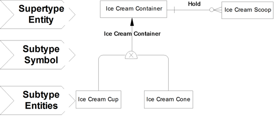
· Each Ice Cream Container may hold one or many Ice Cream Scoops.
· Each Ice Cream Scoop must be held in one and only one Ice Cream Container.
· Each Ice Cream Container must be either an Ice Cream Cone or an Ice Cream Cup.
· Each Ice Cream Cone is an Ice Cream Container.
· Each Ice Cream Cup is an Ice Cream Container.
EXERCISE 5: Reading a Model
Practice reading the relationships in this model. See the Appendix for my answers.

Note that I called one of the relationships ‘Contains’, as there is already a relationship called ‘Contain’, and I’ve decided to keep the relationship names and codes[1] unique within the model.
A better way to handle potentially duplicate names is to display ‘Role Names’ on the diagram instead. See Chapter 13.
In PowerDesigner, subtype symbols have names, and it’s up to you what you call them. The most obvious choices are:
1. The name of the supertype entity (e.g. Transaction)
2. The name of the attribute we use to distinguish between the subtypes (e.g. Transaction Type)
In this model I used the name of the attribute. Either naming approach would be valid. Choose the one that’s most meaningful to you.
· A rule is visually captured on a data model by a line connecting two entities, called a relationship. · Data rules are instructions on how data relate to one another. Action rules are instructions on what to do when data elements contain certain values. · Cardinality is represented by the symbols on both ends of a relationship that define the number of instances of each entity that can participate in the relationship. The three simple choices are zero, one, or many. · Labels are the verbs that appear on the relationship lines. Labels should be as descriptive as possible to retain data model precision. · A recursive (reflexive) relationship is a rule that exists between instances of the same entity. · Subtyping groups the common properties of entities while retaining what is unique within each entity. |