CHAPTER 9
What can PowerDesigner do for me?
Deep is the insight
That metadata provides
Models, Objects, Links
Using the tool features listed in Chapter 8, you will produce a lot of complex, interrelated information about data models, real-world data artifacts, and other types of models. We refer to all this ‘about’ information as ‘metadata’. The description of an entity in a Logical Data Model is part of the entity’s metadata, as is the link from the entity to a table in a Physical Data Model. The description of the table and the link from the table to a database view in another Physical Data Model are also metadata. The metadata underlying your data models is a key source of knowledge about your business, the data it requires to operate, and the way in which that data has been or will be implemented in your systems.
What is metadata?
If you ask us for our definition of metadata, before we can even think about what it really means, we hear ourselves say aloud, “Data about data.” This is, however, a poor definition. As we will see from our discussion of definitions in Chapter 6, a good definition is clear, complete, and correct. Although the “Data about data” definition is correct, it is not clear or complete. It is not clear, since business people need to understand what metadata means and I have never found someone who responds with “Ah, I get it now” after hearing the “data about data” explanation. It is not a complete definition because it does not provide examples nor distinguish how metadata really differs from data. Therefore, we need a better definition for the term metadata.
Steve spoke on a metadata-related topic with several DAMA chapters and user groups. Collectively, they came up with the following definition for metadata:
Metadata is text, voice, or image that describes what the audience wants or needs to see or experience. The audience could be a person, group, or software program. Metadata is important because it aids in clarifying and finding the actual data.
A particular context or usage can turn what we traditionally consider data into metadata. For example, search engines allow users to enter keywords to retrieve web pages. These keywords are traditionally data, but in the context of search engines they play the role of metadata. Much the same way that a particular person can be an Employee in one role and a Customer in another role, text, voice or image can play different roles - sometimes playing ‘data’ and sometimes playing ‘metadata’, depending on what is important to a particular subject or activity.
There are at least six types of metadata: business (also known as ‘semantic’), storage, process, display, project, and program.
Examples of business metadata are definitions, tags, and business terms. Examples of storage metadata are database column names, formats, and volumetrics. Examples of process metadata are source/target mappings, data load metrics, and transformation logic. Examples of display metadata are display format, screen colors, and screen type (e.g. tablet vs. laptop). Examples of project metadata are functional requirements, project plans, and weekly status reports. Examples of program metadata are the Zachman Framework, DAMA-DMBOK, and naming standards documentation.
PowerDesigner metadata scope
PowerDesigner provides a single modeling environment that brings together the techniques and notations of business process and requirements modeling, data modeling, enterprise architecture modeling, and UML application modeling. The scope of the metadata supported by PowerDesigner is therefore much wider than just the metadata required to describe and manage your data.
PowerDesigner enables you to integrate the design and maintenance of your organization's core data with your business requirements, business rules, business processes, Enterprise Architecture, Glossary of Terms, Object-Oriented code, XML vocabularies, and data movements. By providing you with a comprehensive set of models at all levels of abstraction, PowerDesigner helps you broaden the reach of your iterative design process to all aspects of your system architecture, from conception to deployment, and beyond.
PowerDesigner does not impose any particular software engineering methodology or process. Each organization can implement its own workflow, defining responsibilities and roles, describing what tools to use, what validations are required, and what documents to produce at each step in the process.
PowerDesigner Data Models
PowerDesigner provides support for eleven types of models, plus the Multi-Model Report. Which models are available to you depends upon the PowerDesigner edition you have licensed. Table 9.1 describes the models of most direct relevance to the data modeler; see Chapter 25 for information regarding the other types of model that are available.
The descriptions in Table 9.1 describe the broad characteristics of each type of model. In Section IV we will introduce six specific types of data models, each of which can be supported by one or more of the PowerDesigner models listed in the table.
Table 9.1 PowerDesigner Data Models
Conceptual Data Model (CDM)
| A Conceptual Data Model (CDM) helps you identify the principal entities of importance to the business, their attributes, and the relationships between them. A CDM is more abstract than a logical (LDM) or a physical (PDM) data model. |
Logical Data Model (LDM)
| A Logical Data Model (LDM) helps you analyze the structure of an information system, independent of any specific physical database implementation. A LDM has migrated entity identifiers and is less abstract than a Conceptual Data Model (CDM), but does not allow you to model views, indexes, and other elements that are available in the more concrete Physical Data Model (PDM). |
Physical Data Model (PDM)
| A Physical Data Model (PDM) helps you analyze the tables, views, and other objects in a database, including the multidimensional objects necessary for data warehousing. A PDM is more concrete than a conceptual (CDM) or logical (LDM) data model. You can model, reverse-engineer, and generate for all of the most popular DBMSs. |


 When we refer to PowerDesigner models in this book, we use the three-letter codes shown above – CDM, LDM, and PDM. When we speak about the ‘Logical Data Model’ or the ‘Physical Data Model’, we’re referring to the types of models described in Section IV.
Data Modeling Feature Comparison
PowerDesigner has a wide breadth, so it is useful to many people, but just how useful is it? Is it a jack-of-all-trades and master of none? If it was, then we wouldn’t have written this book, you can be sure of that.
Using the tool feature categories that we introduced in Chapter 8, let us sell PowerDesigner’s data modeling capabilities to you.
Core Modeling
PowerDesigner supports the majority of the features listed in Chapter 8. Here are just some of the ways in which this support is provided.
Support For Multiple Types Of Data-Related Models
PowerDesigner supports all six types of data models described in Section IV.
Linking and Syncing Models
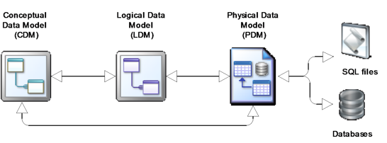
One of the great features of PowerDesigner is the ability to take an existing model and generate another model of the same type, or a different type of model. A detailed record is kept of the links between models, and between objects in those models. This information is available for carrying out impact analysis, and is also used to ensure that models stay synchronized, where necessary. You can also import from or generate SQL files and database schemas. When generating a new model, you can be selective about which objects to generate from in the original model.
Sybase refers to these capabilities as ‘Link and Sync’. Figure 9.1 shows a subset of the link and sync capabilities that are most relevant to a data modeler. For simplicity, it doesn’t show the ‘same model type’ generation capabilities, which is supported for all these types of models; for example, you can generate a LDM from a LDM.
Figure 9.1 Data model generation links
One File Per Model
In the real world, it’s possible for the Logical and Physical views of data to be radically different, especially if the Physical view is based on one or more packages supplied by third party vendors. Supporting these views requires a loose coupling of Logical and Physical Data Models, or perhaps a loose coupling of Conceptual and Physical Data Models. In some other data modeling tools, achieving looser coupling between the Logical and Physical Data Models, or mapping any of those models to objects in models held in other files, can be difficult and cumbersome.
The way in which PowerDesigner manages models allows us to work flexibly. Each model is held in a separate file, and contains details of ‘target models’ that it is linked to. These target model entries are created automatically when you run standard PowerDesigner functions, such as generating a Logical Data Model from a Physical Data Model, creating mappings between models with the Mapping Editor, or creating shortcuts in a model to objects or diagrams in another model. The models can be as tightly or loosely coupled as you like. The model links can be interrogated and revised, and also shown graphically. There is no practical limit to the number and types of models you can generate and map together.
Multiple Notations Supported
PowerDesigner provides support for several different modeling notations, which you can vary from model to model. You can also change the notation in use in a model at any time, though you will have to be careful, as the types of model objects supported do vary somewhat, according to the notation.
You can change the notation for a model via the Model Options. If you click on <Set as Default>, the chosen notation becomes the default notation for new models of that type. PowerDesigner is supplied with a number of user profiles that allow you to ensure that your modelers use notation consistently.
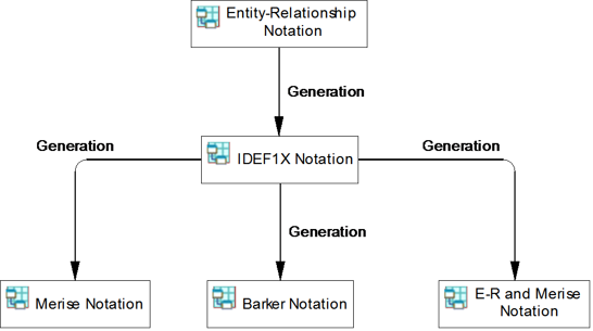
![]() For example, to create the notation samples in Table 9.2, I created a simple model using one notation, then generated additional models, each of which uses a different notation. This allowed me to create five models of the same type, identical except for notation differences. Using the PowerDesigner concept of a Project, I produced Figure 9.2, which shows you the generation links between the models. Each box in the diagram represents a model.
For example, to create the notation samples in Table 9.2, I created a simple model using one notation, then generated additional models, each of which uses a different notation. This allowed me to create five models of the same type, identical except for notation differences. Using the PowerDesigner concept of a Project, I produced Figure 9.2, which shows you the generation links between the models. Each box in the diagram represents a model.
Table 9.2 describes the data modeling notations supported by PowerDesigner. All of the notations use rectangles to represent data objects (entities, tables or views); there are some exceptions – see Table 9.2. The notations all use lines to denote relationships or references, though the line style varies, as do the symbols used at the line endpoints. In the CDM/LDM examples, Relationship_2 is a dependent relationship; see Chapter 7 for more information. For in-depth comparisons of modeling notation, you are advised to read David Hay’s articles on the subject, available from www.essentialstrategies.com.
Table 9.2 Notations supported by PowerDesigner
CDM and LDM Notation | PDM Notation |
Entity/Relationship (Information Engineering)
Relationships are represented by solid lines with a variety of notations at the endpoints, including the ubiquitous “crow’s feet”. Relationship lines have separate symbols for optionality and cardinality. Inheritances (Subtypes) are represented by a half moon symbol. This notation is used throughout this book. | Conceptual
References are represented by solid lines with a variety of notations at the endpoints, including the ubiquitous “crow’s feet”. Reference lines have separate symbols for optionality and cardinality. This is not the default PDM notation in PowerDesigner, but we use it in this book for consistency with the CDM and LDM. |

