
If you want to prevent anyone from changing your symbols, you can protect them using ‘Protect Symbols’ on the Symbols menu. If you do this, remember three things:
· The object is not protected, merely the symbol
· Only direct access to the symbol is prevented - changes made via Display Preferences can still affect symbols
· You can only unprotect a symbol by unprotecting all protected symbols on a diagram – of course you can re-apply protection immediately afterwards.
Bending and Straightening Link Symbols
You can change the corners on link symbols. The results depend on the style of your line, specifically whether or not it has right-angled corners. See “Display Preferences for Relationships” in Chapter 13, to find out more about line corner styles.
You can add one or more handles to a line by holding down <Ctrl> and clicking on the line. In Figure 10.45, we have added two handles.
Figure 10.45 Two new handles

If the line style does not have right-angled corners, we can drag the two new handles to change the shape of the line, as shown in Figure 10.46.
Figure 10.46 A lightning strike

If the line style does have right-angled corners, attempting to drag individual handles may just result in the removal of the handles you added. You need to drag the line segments – the parts in between the handles. See Figure 10.47.
Figure 10.47 Dragging a line segment


There is an exception to the above rule – you can drag a right-angled corner to a new location and re-route the whole line as shown in Figure 10.48.
Figure 10.48 Dragging a right-angled corner


You can also drag a line or portion of a line up and down or left and right, to alter the location it attaches to a symbol. This is useful when you have more than one line attached to one side of a symbol, as shown in Figure 10.49.
Figure 10.49 Moving a line

To remove a handle (and corner), press <Ctrl> and click on the handle you want to remove. Pressing <Ctrl+H> or <Ctrl+L> may also have the desired effect. See “Laying Out Diagrams”, later in this chapter.
Connecting a Link Symbol to a Different Object
 You can drag a link symbol from one object to another. This works for any kind of link, even CDM/LDM relationships and PDM references.
- Click a link symbol in the diagram.
- Drag one of its end handles to a different object.
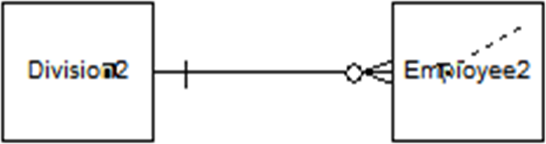
In the left-hand image in Figure 10.50, the line handle that had been inside the entity Division2 was dragged across to the entity Employee2. The left-hand image shows the result – when the mouse button was released, the line end was moved, so the line now connects Employee2 to itself. In technical terms, the relationship became a recursive (or reflexive) relationship – see Chapter 5 to find out what these are.
Figure 10.50 Moving the end of a line

![]() “Dragging a Link Symbol from One Object to Another” (Core Features Guide)
“Dragging a Link Symbol from One Object to Another” (Core Features Guide)
You can also change the entity or table at either end of a relationship or reference via their property sheet.
Renaming Objects and Symbols
 How easy is it to change the name of an object or model? It is very easy! In fact, there are several methods available.
By the way, some of these methods work just as well for sub-objects.
The Two-click Method for Renaming an Object
Works in the Browser | ü |
| Works in Diagrams | ü |
Works for sub-objects in the Browser | ü |
| Works for sub-objects in Diagrams | û (See the three-click method) |
|
|
| Works for other properties in Diagrams | ü (Try it on relationship role names and cardinalities) |
1. Click on the object or symbol name to select it
2. Click again to edit the name.
If your clicks are too close together, you’ll open the property sheet instead; that’s not a problem, because you can change the name there as well.
The Three-click Method for Renaming an Object
Works for sub-objects in Diagrams | ü |
1. Click on the symbol to select it
2. Click on a sub-object name to select it
3. Click again on the sub-object name to edit it
The <F2> Method for Renaming an Object
Works in the Browser | ü | Works in Diagrams | ü |
Works for sub-objects in the Browser | ü | Works for sub-objects in Diagrams | û See the three-click method |
1. Select the name of an object in the Browser or select a symbol on a diagram
2. Press <F2>, and change the name
3. Press <Enter> or click anywhere else to save the new name
The Property Sheet Method for Renaming an Object
Open the property sheet and change the object name in the ‘General’ tab.
The Two-handed Method for Renaming an Object
Works in the Browser | û | Works in Diagrams | ü |
On a diagram, hold down <Ctrl> and right-click the symbol text to select it for editing.
Accessing Objects from a Diagram
Most of the symbols on a diagram represent underlying objects, so you can use symbols to access the object definitions. You can also use them as a pathway to other related diagrams. We will have a brief look at this in Chapter 16.
To find the underlying object in the Browser, either:
· Right-click the symbol and select ‘Find in Browser’
Or
· Select the symbol and press <Ctrl+B>.
There are several ways to access the object’s property sheet from a symbol:
· Double-click the symbol
· Right-click the symbol and select ‘Properties’
· Select the symbol and press <Alt+Enter>.
Showing and Hiding Symbols
The Show Symbols dialog (Figure 10.51) lists all the objects that you can display on the diagram and allows you to choose which ones to show or hide. When you hide a symbol, you do not delete the symbol or the object, the symbol is merely hidden from view. If you re-select the object later, it will re-appear in the same position as it was before you hid it.
Figure 10.51 Show symbols dialog

There are three ways to open the Show Symbols dialog:
· Symbol|Show Symbols
· Right-click the diagram background and select Diagram|Show Symbols
· Right-click the diagram name in the Browser, and select Show Symbols.
Each sub-tab in Figure 10.51 shows one type of object. If shortcuts, extended dependencies and/or free symbols are present in the package, they appear on their own sub-tabs. You show and hide symbols by selecting or deselecting them. The Select All and Deselect All tools allow you to select or deselect all objects on the current tab, or all tabs. The option shown in Figure 10.51 will include all the objects on all the tabs.
If you have other models of the same type open, you can use the Add Objects tool  to select objects in other models of the same type. Any objects selected are included in your model as shortcuts. For example, if you include the entity Order from another model, it will appear in the list of entities for your current model, with a shortcut arrow on the icon.
When you hide or show links or objects with links, the following rules apply:
· Hide an object - Links attached to the hidden object are also hidden
· Show an object - Links attached to the object are shown if the object at their other extremity is already visible
· Show a link - The objects at both ends are also shown.
In a CDM, the following rules apply:
· Hide a parent entity - Inheritances for which the hidden entity is the parent are also hidden.
· Show an association - Entities and association links attached to the association are also shown.
· Show an association link - Entities and associations attached to the association link are also shown.
· Show an inheritance - Parent and child entities and inheritance links attached to the inheritance are also shown.
· Show an inheritance link - Parent and child entities and inheritances attached to the inheritance link are also shown.
To hide one or more symbols without using this dialog, select them and choose Hide Symbols from the Symbol menu. You can also right-click one of the selected symbols and choose Edit|Hide Symbols from the contextual menu.
To show a symbol without using the dialog, simply drag the object into the diagram from the Browser or another diagram. If you drag the symbol from another package or model, a shortcut to the object will be created in the destination model.
It may be better to hide a symbol than to delete it from a diagram. If you hide a symbol and then decide to show it again, it will re-appear in the same position. If you delete a symbol and then decide to show it again, you will have to decide where to put it. This could save a great deal of time if you need to hide and then re-display many linked symbols.
There is another way to add missing link symbols – the ‘Complete Links’ command. See “Including Missing Relationships” in Chapter 13.
![]() “Showing and Hiding Symbols” (Core Features Guide)
“Showing and Hiding Symbols” (Core Features Guide)
YOUR TURN TO PLAY
- Open any diagram in the Project Management LDM and open the Show Symbols dialog.
- Look through the tabs and select some symbols to add to the diagram. Include at least one of the more unusual types of symbols, such as other diagrams, and then click on <OK>. The symbols will now appear on your diagram in the default style.
- Open the ‘Show Symbols’ dialog again, de-select at least one symbol, and click <OK>. The symbol will have disappeared from the diagram.
- Open the ‘Show Symbols’ dialog for a third time, and check the entries for the symbols you de-selected in step 2 - they are listed as ‘hidden’. Select them again and click <OK>. The symbols will reappear on the diagram.
Communicating Your Message
A diagram is a communication tool. For communication to be effective, the message needs to be clear and unambiguous. The content, layout, and style of the diagram are key factors in communicating the message.
There are several ways of improving the readability of your diagram:
· Add a title box, annotations, comments, and other graphical symbols
· Add external files and link them to your model objects
· Exclude objects or properties of objects that are not relevant to the audience
· Exclude sub-objects (such as attributes in an entity symbol) that are not relevant to the audience
· Use color, line, and font styles to convey meaning
· Align your entity symbols to make it easier to visually scan across and down the diagram.
For a more comprehensive discussion of improving readability, see Steve’s book Data Modeling Master Class Training Manual 2nd Edition (Hoberman, 2011, Module 7).
We’ll discuss re-arranging the layout in Chapter 13, where we show you how to create and work with relationships.
Figure 10.52 illustrates some of the graphical embellishments that are available via the Toolbox. None of the embellishments affect the underlying model at all.
Two of the symbols have been changed from their original image via their contextual menu. Just right-click any image and select ‘Change Image’. You can replace the current image with clip art, PowerDesigner icons, Windows icons, or anything else you like. If you change the symbol image for a real object such as an entity, you may need to add the object name as a separate text box, as most images cannot contain object properties. You can avoid this issue by using the ‘Custom Shape’ tab from the format menu to change the symbol shape.
Figure 10.52 Graphical embellishments
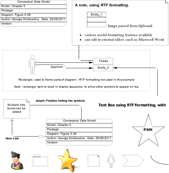
The lines connecting symbols on Figure 10.52 are known as ‘Traceability Links’. We’re using them to link decorative symbols, so they’re only recorded in the diagram. On Figure 10.53, we’ll see another type of link which does affect the underlying objects.
The way you create decorative symbols is no different from how you created entities. The first step is to click on a tool on the Toolbox; what you do next depends on the type of symbol.
For link symbols, click on the first symbol and drag the mouse to the second symbol. If you release the mouse button in empty space, you will create a bend in the link. Create as many bends as you want to, and then click on the second symbol.
For other symbols, you have two choices:
· Click on the diagram to create the symbols in their default size, in the same way you would create entities
or
· Click on the diagram and drag the mouse; then let go of the mouse button when your symbol is the required size.
You can change the format of any symbol or link. In Figure 10.52, for example, I changed the symbols at the end nodes on the line that connects the title box to a note.
| “Symbols” (Core Features Guide) |
You can also import external images, by pasting from the Windows clipboard, or by importing from a file. See the ‘Import Image’ option on the ‘Edit’ menu.
In Figure 10.53, we can see examples of presentation techniques that expose the details of the data model, and examples of the formatting capabilities. We are constrained by the monochrome presentation of this book, which prevents us from demonstrating the use of color and shading.
Figure 10.53 Format and content of object symbols

Each of the four entities in Figure 10.53 is displayed differently, due to changes in the selection of content and style.
The Thesis entity symbol shows the list of attributes, the plural name, and the description, it also has a shadow. Note that the plural name is not a standard PowerDesigner property – it was introduced via a model extension, which we will discuss again later. The line style and fonts were changed in Entity_5, and we’re also showing more detail of the attributes. The symbol for Entity_4 has been completely replaced by an image of door keys.
The dashed line between Thesis and Lecturer is a traceability link, telling us that Thesis is influenced in some way by Lecturer. We have chosen to classify the link as a <<Possible Relationship>> by updating the Link Type. You will try this for yourself in Chapter 18.
| “Creating Traceability Links” (Core Features Guide) |
Changing the Content of Symbols
As we showed in Figure 10.53, you have a lot of control over the object properties displayed in a symbol.
You’ll remember that you can access the Display Preferences by right-clicking a blank area of the diagram. You can see the dialog in Figure 10.54.
Figure 10.54 Display Preferences dialog

All the standard types of symbols in the model are listed on the left. The term ‘Free Symbol’ refers to the graphical embellishments we looked at earlier.
The General Settings category allows you to control the general look of the diagram. The ‘Word Wrapping’ tab allows you to change the way in which long object names are handled. Word wrapping is turned off by default. The ‘Format’ tab allows you to set the default format (but not font) for all symbols.
Figure 10.54 shows the General Settings applicable to data models. The two settings under the ‘Links’ category were introduced in PowerDesigner Version 16. Further settings are available for other types of models.
When you select one of the symbol types in the dialog, you will be presented with two tabs, ‘Content’ and ‘Format’. We will look at the ‘Format’ tab in the next section.
Figure 10.55 shows the default ‘Content’ tab for entities – it shows the properties that are currently available for display on entity symbols. If you select a different type of symbol on the left, the content tab changes appropriately.
Figure 10.55 Selecting symbol content

The checkboxes in Figure 10.55 allow you to choose the properties to display on symbols. If you click the <Default> button, the preferences are reset to the current default values for this type of model. Click the <Set As Default> button to set the current Display Preferences as the default for this type of model – PowerDesigner will apply these preferences to all new diagrams of this type. You will also see these buttons in other dialogs, such as ‘Model Options’, where they have the same affect.
Once you have configured your preferences, you can apply them to the current diagram by pressing <OK>.
Alternatively, click on <Apply To> to select other diagrams to apply the changes to. After selecting your diagrams, you will be asked whether you want to apply your changes to all the symbols in the selected diagrams. If you select ‘Yes’, all existing and new symbols will reflect your changes to the Format, General, and Content display preferences. If you select ‘No’, only new symbols will reflect your changes.
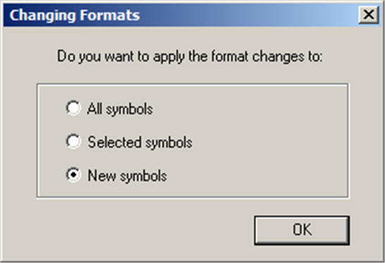
When you click on <OK> in the ‘Display Preferences’ window, you have a choice of how to apply the changes in the current diagram:
All symbols | Apply the changes to all symbols on the diagram |
Selected Symbols | Apply the changes to selected symbols on the diagram |
New Symbols | Existing symbols are untouched, and new symbols will comply with the new preferences |
 If you want to apply different Display Preferences to just some of your symbols, you must select those symbols and access Display Preferences via the Tools menu, not by right-clicking the diagram.
To change the list of available properties, click on the ‘Advanced’ button. Figure 10.56 shows the result.
Figure 10.56 Customizing symbol content
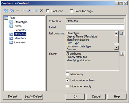
The left-hand side of the ‘Customize Content’ dialog shows the properties currently selected for display on entity symbols. The right-hand side shows the detail of the property selected on the left, in this case the Attributes property. This is a collection of sub-objects, so we can choose the sub-object properties available for display, as well as define a set of filters to limit the sub-objects displayed. 
The <Default> and <Set As Default> buttons have the same effect as those in Figure 10.55.
In this dialog, you need to remember the distinction between Attributes in entities, and attributes as object properties, that we mentioned before. The word ‘Attributes’ in Figure 10.56 refers to Attributes in entities. In the next few paragraphs, we refer to ‘attributes’ as properties of PowerDesigner objects. Most of the properties listed on the left-hand side of Figure 10.56 are simple properties of objects, referred to as ‘attributes’. If you select such a property on the left-hand side, the right-hand pane is simpler than shown in Figure 10.56. You will be able to change the following:
Label | Used in the list of properties in Display Preferences – this defaults to the property name, so you only need to enter something here if you want to use different words. |
Prefix and Suffix | Used to label the entry on the symbol. |
Alignment | Choose how you want to align the property value within the symbol |
Mandatory | If you select this box, the property will always be displayed on the symbol and cannot be de-selected in the Display Preferences dialog. |
Figure 10.57 explains the toolbar icons found at the top of the “Customize Content” form shown in Figure 10.56.
Figure 10.57 Toolbar for customizing content

The Horizontal and Vertical Layout options were introduced in PowerDesigner Version 16. They allow you to arrange properties side by side or one under the other. Vertical Layouts are often used in conjunction with a Horizontal Layout, to provide several columns of attributes.
In addition, there are two checkboxes:
Small icon | Places a small object icon in the top-left corner of the symbol in detail mode. The icons can be varied according to the values of the property. |
Force top align | Forces top alignment in the symbol for object attributes, such as Name. If this option is not selected, these properties are centered on the vertical axis. |
When you click on the ‘Add Attribute’ button, you are presented with a list of the available property attributes. Figure 10.58 shows the attributes available for entity objects. Most of them are common to all types of object, some are specific to entities.
There are two tabs shown in Figure 10.58, one for standard Attributes, and the other for Extended Attributes, introduced via model extensions.
Figure 10.58 Choose from the available properties (attributes)

Just select the attributes that you want to have available for display and click on <OK>.
To add one or more Collections, start by clicking the ‘Add Collection’ button in Figure 10.57, and continue in the same way as you would when adding Attributes.
| “Customizing Content Display Preferences” (Core Features Guide) |
YOUR TURN TO PLAY
1. Right-click any data model diagram that displays entities, select ‘Display Preferences’, and click on ‘Entity’ on the left. Ensure all the checkboxes on the right are cleared and click <OK>. In the ‘Changing Formats’ window that appears next (Figure 10.59), choose ‘All Symbols’ and click <OK>. All the entity symbols will change to a simple rectangle, containing only the entity name. The symbols may have shrunk due to the reduction in content.
Figure 10.59 Changing Formats window
PowerDesigner will ask you if you want to apply the preferences to all the symbols in the selected diagram(s), and gives you the following options:
· Yes – All existing and new symbols will reflect your changes to the Format, General, and Content display preferences.
· No – Only new symbols will reflect your changes. Only the General and Content display preferences are applied to existing symbols. The Format changes are canceled.
· Cancel – Your changes will not affect any symbols in any diagrams except the current one.
2. Now open the ‘Display Preferences’ again, select ‘Entity’, and click on <Advanced> to show the list of available properties. Follow these steps to add the Description property to the list:
· Select the Attributes property and click the ‘Add Separator Line’ button.
· Click the ‘Add Attribute’ button.
· Select the Description property and click on <OK>.
· The Description property is added to the property list in the ‘Customize Contents’ window, separated from the Attributes property; click on <OK> to close this window.
3. Click on <OK> to close the Display Preferences, select ‘All Symbols’ in the ‘Changing Formats’ window, and click <OK>.
4. If your entities have Descriptions, they will appear in the symbols – add a Description to an entity and see what happens.
5. Add some Free Symbols from the Toolbox, and add links between symbols. Remember to drag the mouse from one symbol to another when creating links.
Figure 10.60 shows the new list of available properties.
Figure 10.60 Revised list of available properties

Formatting Symbols
You can change the size, line style, fill, shadow, font, alignment, shape, and content of symbols in the Symbol Format dialog. Some items may not be available if your modeling methodology restricts the modification of symbol format or content.
You will arrive at the Symbol Format dialog when changing the format of:
· One or more individual symbols – select the symbols and press <Ctrl+T>, or select Format on the Symbol menu, or select Format from the contextual menu.
· All symbols - via display preferences (see “Changing the Content of Symbols”, earlier in this chapter).
Figure 10.61 shows a typical Symbol Format dialog and Table 10.9 describes each tab. Note that the ‘Sub-Objects’ and ‘Content’ tabs are only available for selected objects, not via Display Preferences.
| The Content tab allows you to show a different set of properties on selected symbols – for example, you could show more or less detail of the attributes. The Sub-objects tab can be used to hide selected sub-objects from a symbol, such as attributes on an entity symbol. There is a useful keyboard shortcut to adjust symbols to fit their content – select all the symbols you wish to adjust and press <Ctrl+J>. |

![]() “Symbol Format Properties” (Core Features Guide)
“Symbol Format Properties” (Core Features Guide)
Figure 10.61 Symbol Format dialog

Get and Apply Format
On the contextual menu for symbols, you may have noticed the commands Get Format and Apply Format. They provide a simple, effective way of transferring the style and content selection from one symbol to another. It even works between different types of objects and between different types of models. For example, you can ‘get’ the style of a table in a PDM, and ‘apply’ it to relationships in a CDM.
The first step is to right-click a symbol whose style you want to mimic elsewhere, and select Get Format. To apply the style to one symbol, just right-click that symbol, and select Apply Format. If the symbols represent the same type of object, all the format and content preferences are copied to the second symbol. Where the symbol types or model types are different, the results vary, but you should probably see some changes.
To apply the format to multiple symbols at the same time, select the symbols, right-click on any one of them, and select Apply Format.
| “Selecting, Editing and Resizing Symbols” (Core Features Guide) “Bending and Straightening Link Symbols” (Core Features Guide) “Aligning Selected Symbols” (Core Features Guide) “Arranging Symbols Using the Symbol Menu” (Core Features Guide) |

Table 10.9 Symbol Format dialog tabs
Tab | Description |
|---|---|
Size Tab | The ‘Size’ tab controls the size of the symbol and how the size can be manipulated. |
Line Style Tab | The ‘Line Style’ tab controls the color, size, and format of lines (for link and other one-dimensional symbols) and borders (for two-dimensional symbols, such as classes or tables). You can modify the line style of any symbol in the model. |
Fill Tab | The ‘Fill’ tab controls the color, content, and effects for symbol filling. |
Shadow Tab | The ‘Shadow’ tab allows you to add a standard, 3D effect or gradient shadow to objects in a diagram. |
Font Tab | The ‘Font’ tab allows you to define the display preferences for the font, size, style, and color of text associated with symbols in the model. When you modify font preferences, they apply to all existing and new symbols.
|
Text Alignment Tab | The ‘Text Alignment’ tab allows you to define the alignment of text in text boxes and rectangles, ellipses, rounded rectangles, and polygons. Note: |
Custom Shape Tab | The ‘Custom Shape’ tab allows you to define a new symbol shape for most non-link symbols. |
Sub-objects Tab | The ‘Sub-objects’ tab is only available when you open the ‘Format’ tab after having selected a single object that is displaying sub-objects. It gives you very fine control over the sub-objects that you want to display inside your object symbol. For each individual sub-object, you can decide whether to display it or not, and what font to use for its display. Note: For a collection of sub-objects to be available for selection and customization, the collection must be selected for display in the object's content display preferences. Where the number of lines to display for a collection is limited in the display preferences, that limit will take precedence over any choices you make here. Each collection of sub-objects that is enabled in the display preferences has its own sub-tab. For each sub-object, you can: · Select to display or hide it in the parent object symbol by selecting or deselecting its checkbox in the [D]isplay column. · Apply a specific font to its display by clicking the Select font tool or the ellipsis button in the Specific Font column. Note: When not all sub-objects in a collection are selected for display, the parent object symbol will display ellipses to indicate that more items are available. |
Content Tab | The ‘Content’ tab allows you to specify the information that you want to display on the symbol. The properties that are listed on this tab as being available for selection are controlled by the content display preferences. |
YOUR TURN TO PLAY
1. Right-click on the name of the Project Management LDM in the Browser, click on New, and then Logical Diagram. The property sheet for the new diagram is displayed. Change the diagram name to ‘New Diagram 1’ and click on <OK>. The new diagram appears in the list of diagrams in the Browser. That’s how easy it is to create a diagram.
2. Here’s another way to create a new diagram. Open the ‘Main Diagram’ and select the ‘Employee’ entity; then select the menu option Edit|Select Connected Symbols; five more entities are now included in the selection. Hold down the <Shift> key, and click on the Activity entity to add that to the selection. You may need to press <F8> to view the whole diagram, so you can see the Activity entity. Right-click on any one of the selected symbols, and select Create Diagram from Selection. A new diagram is created with a default name, containing the selected symbols – the symbols have the same appearance and layout as they did in ‘Main Diagram’. This is the easiest way to create a diagram with the same display preferences as an existing one.
3. Let’s assume that this view of the model doesn’t require the Member entity, so select it and press <Delete>. PowerDesigner asks you if you want to delete the object itself, or just the symbol. See Figure 10.62.
Figure 10.62 Confirm Deletion

4. Select ‘Delete Symbols Only’ and click on <OK>. The entity has been removed from the diagram, but you can still see it in the Browser.
When PowerDesigner asks if you also want to remove the object definition, the default answer is ‘Yes’. If you accidentally remove definitions, press <Ctrl+Z> to bring them back.
Remember that you can hide symbols instead of deleting them – see “Showing and Hiding Symbols”, earlier in this chapter.
5. Now to change the information displayed on Entity symbols. Right-click a blank area of the diagram and select ‘Display Preferences’. Click on ‘Entity’ in the list on the left-hand side, and make sure that all of the checkboxes are blank so the Entity symbols will only contain the Entity name. Now click on the ‘Format’ tab, and then click on ‘Modify’. Figure 10.63 shows the options available. Select the ‘Font’ tab.
Figure 10.63 Modifying Symbol Format
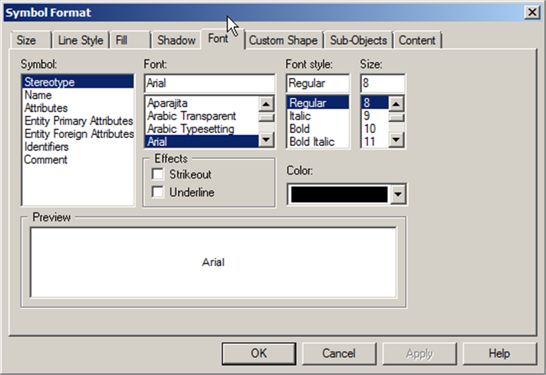
This is the standard Symbol Format window, which you can use to format selected symbols or to set diagram defaults. Have a look at the tabs and try out some of the options, if you like, but make sure that you at least change the name format. Click on the ‘Font’ tab and PowerDesigner will present a list of Symbol properties on the left, with the font options for each one to the right of that. To change the font for the Symbol name, click on ‘Name’ on the left and change the font to Arial, Bold, Size 12.
The first entry in the list of Symbol properties is NOT the name. I have lost count of the number of times that I intended to change the format of the Name, but forgot to select it on the left first. Remember you can always undo any change you make accidentally, or cancel the whole operation.
6. Press <OK> and click on ‘Apply To’ in the ‘Display Preferences’ dialog. This allows you to apply the formatting changes to other diagrams in your model. Select the diagram called ‘Symbol Test’ and click on <OK>.
7. In the confirmation window, select ‘Yes’, and the ‘Display Preferences’ window is re-displayed. Click on <OK> to apply the changes.
8. PowerDesigner now displays the ‘Changing Formats’ window (see Figure 10.56). Choose ‘All Symbols’, so that the style is applied to all the symbols on the diagram, as well as to new symbols.
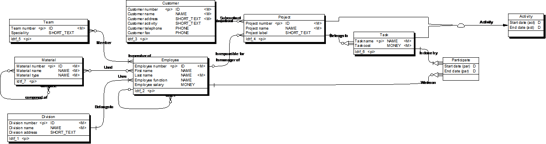
The entities in your diagram have all been re-sized, and the entity names are now in a larger, bolder font, as shown in Figure 10.64.
Figure 10.64 Project Management LDM in progress

You can change the display preferences for one or more selected symbols. Select the symbols you want to change, click on the Tools menu, and then click on Display Preferences. Make your changes and choose to apply the changes to ‘Selected Symbols’.
![]() “Content Display Preferences” (Core Features Guide)
“Content Display Preferences” (Core Features Guide)
YOUR TURN TO PLAY
The entities are now more widely spaced than they need to be, so you should re-arrange them, placing Employee at the top.
1. Drag the Employee entity to the top and middle of the diagram.
2. Use the mouse and the <Shift> key to select all the other entities, and then drag them to below Employee.
3. Click on the ‘Evenly Space Horizontally’  button on the Layout toolbar.
4. Click on the ‘Align Top’  button on the same toolbar.
5. On the Symbol menu, select Align| Same Width. Now sort out the relationships.
6. Double-click the relationship tool in the Logical Diagram palette to select all the relationships.
7. On the Symbol menu, select Disposition|Arrange Connectors.
Most of the lines now look much neater, but there may still be room for improvement. Make sure all of the relationships are still selected, press <Ctrl+H>, and then press <Ctrl+L>. These commands straighten out any lines that can easily be made horizontal or vertical. The result should look something like Figure 10.65.
Figure 10.65 Partially re-organized diagram

There are just two things to do now: get rid of the entity shadows and move some of the relationship lines. Let’s do the easy part first. Select all symbols and press <Ctrl+W>. All of the shadows will disappear – if not, just press <Ctrl+W> again.
Moving the relationships can be a bit trickier. Lines can be moved by dragging the lines, or by dragging the relationship handles, which show up as small squares at the line ends and on any corners. The handles are shown in Figure 10.66; note that the end handles are inside the entity symbols, not on the edges.
Figure 10.66 Relationship handles

You can slide relationships along entity edges by dragging one of the end handles horizontally or vertically. The line itself is usually a bigger target, so try it now. Click on a line and hold the mouse button down; the line should change into a dashed line which you can easily drag around to reroute the line. In the example shown in Figure 10.66, the line can be dragged to where the word ‘Handles’ is shown, and it will reroute itself to form a right-angle in a different position. If you have problems dragging the vertical part of the line, try dragging the horizontal part instead.
If you want to resize an entity, select it; you’ll see that it also has handles. Drag one of the handles to stretch or shrink the entity in one or both dimensions. If you press <Ctrl+J>, all selected symbols will resize to fit their contents.
Looking at the diagram, it seems that the Division entity should be above the Employee entity. You could drag it with the mouse, but there’s another way, which also ensures that it moves in a straight line. Select the entity; press the <up arrow> key on the keyboard until the entity is as high as you want, and use the left and right arrow keys to move it sideways. The relationship line is continually re-drawn by PowerDesigner. Move the entity around until the relationship line takes a favorable route.
If you now have a gap in the lower entities, select the ones you want to sort out and experiment with the icons on the Layout toolbar (or via the Symbol menu) to line them up and even out the spacing. You can select several entities and use the arrow keys to move them all together, if you like. Finally, you may need to re-adjust the relationship lines. The labels on relationships can also be moved around, as long as you do not try and move them too far from the line. The result may look like Figure 10.67. We have not changed the content or meaning of the model at all, but we have created a new view of part of the model that differs greatly from the original view.
Figure 10.67 The finished diagram

In Figure 10.67, the labels shown for relationships are the relationship names. By default, PowerDesigner places these in the middle of the line. I moved them sideways for clarity. Relationship role names (which have been hidden in Figure 10.67) would be positioned so that they can be read in a clockwise fashion.
To reset relationship labels to their default positions, select them all, and select Disposition|Arrange Attached Text on the Symbol menu.
Perform a quick experiment – in ‘Display Preferences’, make sure that ‘Automatic Link Routing’ is disabled. Now move the Division entity to the right using the cursor keys: – the entity and relationship will slide sideways, until the entity reaches the Chief relationship. From this point, the Belongs To relationship will stop moving sideways. Now move Division back to where it started. In ‘Display Preferences’, enable ‘Automatic Link Routing’, and move Division to the right again. PowerDesigner will continually reroute the relationship and move other relationships, if necessary.
Laying Out Diagrams
PowerDesigner can automatically re-arrange whole diagrams or selected symbols in diagrams for you. There are several different layout styles available; just choose one, and PowerDesigner will rearrange the symbols, simplifying the routing of links by minimizing node and link overlaps, and reducing the distances between related nodes.
Select Symbol|Auto-Layout to open the Auto-Layout window. You can also click on the Auto-Layout tool  on the Layout menu. The Auto-Layout window is shown in Figure 10.68. Only the styles relevant for the current diagram can be selected.
Figure 10.68 The Auto-Layout window

The available layouts are described in Table 10.10. The diagrams in the table show the effect of applying the layout option to the diagram shown in Figure 10.69.
Figure 10.69 The original diagram

Table 10.10 Auto-layout options
Layout Type | Description | ||
|---|---|---|---|
Basic | Provides minimal rerouting for any diagram style. This can be repeated, resulting in different layouts.
| ||
Hierarchical | Highlights the main direction or flow within a diagram. You can specify an orientation[5] for the flow. This example was produced using Left to Right orientation:
In this example, the parent entity in a relationship (Entity 1) is always on the left. Supertype entities are always on the right. Choosing the ‘Right to Left’ orientation would reverse the direction of every relationship:
| ||
Organic | Re-arranges entities to reduce crossing relationships. No attempt is made to define a standard direction for relationships.
| ||
Orthogonal | For undirected diagrams. You can specify an orientation[6] for the flow within the graph. This example was produced using Left to Right orientation:
The result does run from left to right, but individual relationships may be oriented in any direction. Choosing the ‘Right to Left’ orientation would reverse the direction of every relationship. | ||
Circular | Produces interconnected ring and star topologies to emphasize group and tree structures within a network. You can additionally specify a cycle (ring) or radiation (star) shape.
| ||
Tree | To create directed or undirected trees. You can additionally specify an orientation for the flow within the graph. This example was produced using Left to Right orientation:
Choosing the ‘Right to Left’ orientation would reverse the direction of every relationship. |


You don’t have to apply the layout to the whole diagram. If you have selected two or more symbols, you can specify if you want to apply the auto-layout to all symbols or only to the selected symbols.
When applying Auto-Layout to a selection, you can additionally select the ‘Move selection to free space’ option to extract the selected symbols from the main body of the diagram and place them in free space.
 If your selection includes supertype and subtype entities, ensure that you also include the inheritance symbol.
Click <OK> to apply the auto-layout and return to the diagram.
Note: You can click the <Default> button to revert to the default auto-layout settings. Click the <Set As Default> button to set the currently selected style as the default.
PowerDesigner may create graphical synonyms (see next page) for certain symbols in (or adjoining) the selection to minimize the length of connecting links.
If you subscribe to the school of thought that describes effective diagram layout using the phrase ‘Dead Crows Fly East’[7], try out the orthogonal ‘Right to Left’ orientation.
Unless your diagram is very simple, it may be best to apply auto-layout selectively. There are other tools on the Layout toolbar and the Symbol menu to help you to align and re-size symbols to improve the readability of your diagrams.
Graphical Synonyms
A graphical synonym is a duplicate symbol for an object on a diagram. Sometimes, creating multiple symbols for an object in a diagram can improve readability by reducing the length or complexity of links. You can create a graphical synonym by right-clicking a symbol and selecting Edit|Create Graphical Synonym.
To find graphical synonyms of a symbol, right-click the symbol, select Edit|Find Graphical Synonym, and then select a graphical synonym from the list. The graphical synonym will be selected and centered in the diagram window, as shown in Figure 10.70.
Figure 10.70 Selecting a graphical synonym

If Find Graphical Synonym doesn’t appear on the menu, that tells you that the symbol does not have graphical synonyms on that diagram.
There are various ways you can access the ‘Find in Diagram’ window in PowerDesigner, such as right-clicking the object name in the Browser. This window allows you to choose which graphical synonym you wish to have centered in the diagram, as shown in Figure 10.71. To find out more about Graphical Synonyms, see Chapter 13.
Figure 10.71 Find in diagram window

Menus Depend on Models
The menu options available in PowerDesigner depend almost entirely on the currently viewed diagram. If you do not have any diagrams open, most menus will not be available, including the ‘Model’ menu. There are other ways of accessing the commands on that menu, which we will see shortly.
YOUR TURN TO PLAY
On the Window menu, select the option Close All to close all the diagrams open in the Canvas. Now open any diagram in the Project Management LDM and any diagram in the Project Management PDM, and use the Window menu to tile them horizontally or vertically. Click on one of the diagram tabs, and then on the Tools menu. Now click on the other diagram tab, and again on the Tools menu. The list of commands for the PDM is longer than the list for the LDM. There are more generation options, and more automation for common operations. The Database menu is only present when the PDM diagram is current. If you open an XML model, the Database menu is replaced by a Language menu.
When you have many models and/or diagrams open, make sure you are aware of the ‘current’ model before you access the menus. If necessary, click anywhere on a diagram to make it ‘current’. Any selections you make in the Browser will NOT affect the available menus.
Workspaces
In PowerDesigner, you are always working in a Workspace. The Workspace consists of all the Folders, Projects, Models, and External Files you can see in the Browser. You can save the structure of the Workspace in a file, which you can re-open later to recreate your working environment.
A workspace contains all the information you need to perform a modeling task with PowerDesigner. During a work session, every change in the hierarchy of folders and models is saved locally in the workspace. Workspaces tend to be personal, containing folders, files, and projects of interest to a modeler.
So far, we’ve carried out all our work in a single workspace. You can create multiple workspaces, but you can only work in one workspace at a time. Workspaces are saved in files whose names end in ‘.sws’. They do not have property sheets. You can create the following new items in a workspace by right-clicking the workspace in the Browser and selecting New|Item:
· Projects
· Models and multi-model reports
· Folders.
In addition, you can add existing items (including external files, such as text files or Microsoft Office files) to a workspace by:
- Right-clicking the workspace in the Browser
- Selecting Add from the contextual menu
- Browsing to the item in your Windows folders
- Clicking <OK>.
You can also drag files into the workspace from Windows Explorer.
When you have external files referenced in a workspace, you can open them with a double-click – they will open in the default software according to your Windows settings.
You can create a hierarchy of folders in a workspace if you choose to. Please remember that these folders are not ‘real’; they do not exist in your file system anywhere, they are just containers that help you organize your PowerDesigner objects (including other folders).
When you close PowerDesigner, you’ll be asked whether or not you want to save the current workspace. You don’t have to do this, of course, but it will make your life easier if you do. You’ll also be asked if you want to save any models that have unsaved changes; this includes the option to say ‘Yes’ or ‘No’ to saving changes for all unsaved models. Be careful how you use this option if you don’t save models regularly; you may lose changes you made a couple of hours ago but forgot to save.
Each model or file entry in a Workspace is a shortcut to the location of a file in the file system. The shortcut is ‘absolute’ rather than ‘relative’; it points to an actual file location, such as ‘X:ServerFolderFolderProjectProject Model.ldm’. The supplied Demo workspace is different – the filenames include the named path %_EXAMPLES%
If you attempt to open a model and the shortcut doesn’t work, it may have been moved or renamed. PowerDesigner allows you to browse the file system to find the file.
| If you only work on one project or on one set of models, you only need one workspace. If you work on multiple projects, it may be useful to have a workspace for each project. Keep original models and their corresponding generated models in the same workspace, preferably within the same project. |

![]() “Workspaces” (Core Features Guide)
“Workspaces” (Core Features Guide)
Models
Models are the basic work unit in PowerDesigner. You must create a model before you can begin modeling.
Creating a Model
You can create a new, empty model by clicking the New tool  on the Standard toolbar, or by selecting ‘New Model’ on the File menu. PowerDesigner will display the New Model window. The New Model window is highly configurable via Model Category Sets, which we will discuss briefly in Chapter 23. Your administrator may hide options that are not relevant to your work, or provide templates or predefined models to guide you through model creation. When you open the window, one or more of the following buttons will be available on the left hand side:
Categories | Provides a set of predefined models and diagrams sorted in a configurable category structure. |
Model types | Provides the classic list of PowerDesigner model types and diagrams. |
Template files | Provides a set of model templates sorted by model type. |
Figure 10.72 demonstrates two of these views. The background shows the ‘Model Types’ view, with the ‘Categories’ view in the foreground. In the ‘Model Types’ view, the left-hand pane lists the types of model your license allows you to create, and the right-hand pane shows the types of default diagrams that can be created in the selected type of model. The Category view groups diagram types rather than model types. Select a Category on the left, and the available types of diagrams are displayed on the right. Use the ‘Views’ tool on the upper right hand side of the dialog to switch between large icons and a list in the right-hand pane. Below these two panes, the two views show the same fields, which you should check before creating a model.
Figure 10.72 New model window

1. Select either ‘Categories’ or ‘Model types’.
2. Select an entry in the left-hand pane.
3. Select an option in the right-hand pane.
4. Enter a model name. The model name will be the default file name when you save the model for the first time – you can, of course, change the model name after creating it, via the Browser.
5. [PDM] Select a target resource file, which customizes PowerDesigner's default modifying environment with target-specific properties, objects, and generation templates. In Figure 10.72, the resource files available provide specific support for different DBMS. If you need to change the DBMS after creating the model, use the option Change Current DBMS on the Database menu.
6. [optional] Click the ‘Select Extensions’ button (if available) and attach one or more extensions to your model.
7. Click <OK> to create and open the model – the model will probably contain one blank diagram of the type selected in the right-hand pane. If your model is based on a template model, the content will depend on the template.
The code of the model, used for script or code generation, is derived from the model name using the model naming conventions.
There is also a simple way to create a new model in the Browser:
- Right-click a folder or Project node
2. Select New
3. Choose the type of model you want to create
4. The New Model window opens, but only shows the selected type of model.
In this book, we are only concerned with three types of models: Conceptual Data Model (CDM), Logical Data Model (LDM), and Physical Data Model (PDM). See Chapter 25 to find out about the other types of models.
During model generation, PowerDesigner will create models automatically – see Chapter 18.
![]() “Creating a Model” (Core Features Guide)
“Creating a Model” (Core Features Guide)
Removing an Unsaved Model
If you have not saved a new model, it only exists in the workspace, not in the file system. If you’ve created a model by mistake, or just decide you don’t need to keep it, it is easy to remove: just right-click the model name in the Browser, and select Detach from Workspace. PowerDesigner will ask if you want to save it, so click <No> – the model will disappear from the workspace, and all traces of it will be removed.
You can also delete a model by selecting the model name in the Browser, and pressing <Delete>, or by closing the project and/or workspace without saving changes.
GUIDs
When you save a model for the first time, PowerDesigner automatically assigns a unique identifying number called a GUID (Global Unique ID) to the model, and creates a backup copy of your file with the same identifying number. The GUID is used to identify documents in the Repository and during model generation. Every object within the model also has a GUID.
GUIDs are vital for keeping models in sync with the repository, and for linking models to each other. The use of GUIDs allows PowerDesigner to maintain model and object links, even when you rename or move them. GUIDs are actually surrogate keys, which we will discuss in Chapter 7.
Saving Models
If a Project or model contains unsaved changes, PowerDesigner appends an asterisk to the name in the Browser  . You can save one Project or model at a time, or all the models in the workspace.
The following formats are available when you save a model for the first time:
XML | Larger and somewhat slower to load than binary, but the model file can be edited in a text editor outside of PowerDesigner. Recommended for small to medium-sized models. |
Binary | Smaller and faster to load than XML, but cannot be edited outside of PowerDesigner. Recommended for large models. |
To save your model, do one of the following.
· To perform a standard save – just one model: Select File|Save, click the ‘Save’ tool  , or right-click the model entry in the Browser and select Save from the contextual menu. If you did not define a file name when you created the new model, the Save As dialog box asks you to provide a name and a path for the file of the new model.
· To save the model in a different format: Select File|Save As, or right-click the model node in the Browser and select Save As. Change the file type in ‘Save as type’. Unless you supply a different file name, the existing file will be overwritten with the new format.
· To save changes to the workspace and save all changes in every open Project and model: Either click on the ‘Save All’ tool  , press <Ctrl+F3>, or select Save All on the File menu. When you close a workspace, you are prompted to save unsaved changes to projects, models, or the workspace itself.
· To save the model as a new model with the same GUID: Select File|Save As, or right-click the model node in the Browser and select Save As. This allows you to create a backup version of a model with the same GUID as the original. The model will have the same name as the original model, but the filename will be different.
· To save the model as a new model with a new GUID: Select File|Save As New Model, or right-click the model node in the Browser and select Save As New Model. This allows you to develop two separate models in parallel, starting from the same set of model objects. Note that if you check the new model into a Repository, the Update mode will not be available. External shortcuts located in the new model may also not work properly since the identity of the model has changed.
Table 10.11 describes scenarios where you would use Save As and Save As New Model.
Action | New model GUID | When to use |
|---|---|---|
Save As | same as original model GUID | To create a replica of a model, perhaps to share work between modelers, or to experiment with alternative approaches. You can merge the replica back into the original model, either locally using Tools|Merge Model, or by checking it in to the repository (you may need to rename it to match the original model name). To save the model in a different format (e.g. save in binary format to improve performance). |
Save as New Model | different from original model GUID | To create a new model initially based on the contents of an existing model, where the new model will change radically from the original. If you need to do this frequently, consider saving the original model as a template model, or share it via the Library facility. |
To avoid the shortcut changing permanently, close the workspace without saving it. When you re-open it, the shortcut will be OK, though you may have lost other workspace changes. |
![]() “Saving a Model” (Core Features Guide)
“Saving a Model” (Core Features Guide)![]() “Models” (Core Features Guide)
“Models” (Core Features Guide)
Backup Files
Every time you save a model, PowerDesigner creates a backup file, so you can revert to the previously saved version of a file if a catastrophe strikes. The backup file is saved in the same folder as the original file, and the backup file name is derived from the original filename, by replacing the last letter of the file type with ‘m’. For example, the file “Chapter 10.cdb” is the backup for “Chapter 10.cdm”.
In addition, you can tell PowerDesigner to save backup files periodically, depending on the Autosave setting in General Options.
This setting instructs PowerDesigner to save changes to all open models to a recovery backup file at the specified interval. Enabling this option provides you with a recovery option if PowerDesigner or your computer crash before you have had a chance to save your changes. The save will take place after the interval has passed, but only when PowerDesigner is idle for more than ten seconds. Note that saving large or multiple models may take several seconds, and that PowerDesigner will not be responsive while it is performing the save.
Deleting a Model
In “Removing an Unsaved Model” we saw that you can detach a model from the workspace. You can also delete a model from the PowerDesigner workspace. This is almost the same action as detaching the model from the workspace – the difference is that you have the opportunity to run an impact analysis first.
To delete a model, select the diagram node in the Browser and press the <Del> key. The standard confirmation window is displayed in Figure 10.73.
Figure 10.73 Confirmation window

Click on <Yes> to delete the model; click on <No> or press <Esc> to change your mind. Click on <Impact…> to run the impact and lineage analysis for the model, to find out about connections between this model and others. You can find out more about this in Chapter 23 – look for “Impact and Lineage Analysis”.
When you click <Yes>, the entry for the model is removed from the workspace, and from any project diagrams (see the next section) it appears on, but the file containing the model is not deleted. Any references to the model in other models are also not deleted.
The model can be added back to the workspace at any time.
Projects
A Project allows you to group together all the models and other types of documents you need for a particular modeling task, and save them as a single entity in your repository.
Unlike Workspaces, Projects have been designed for sharing with co-workers, either via a common folder, or via the repository. A project can contain one or more project diagrams, which show the connections between models and other documents in the Project. Remember PowerDesigner uses a briefcase icon ![]() to represent a project in the Browser.
to represent a project in the Browser.
PowerDesigner uses the phrase ‘Project Directory’ to refer to the Windows folder where the model files are located, and the phrase ‘Project Folder’ to refer to the Project container in the Browser. To avoid confusion, we use the same convention. Every project has its own Project Directory, usually with the same name as the Project, and project files can be inside or outside the folder – any file that is outside the folder has a shortcut symbol ![]() on the Browser icon. PowerDesigner will move any such file into the Project directory if you need to – just right-click the shortcut symbol, and select Move to Project Directory.
on the Browser icon. PowerDesigner will move any such file into the Project directory if you need to – just right-click the shortcut symbol, and select Move to Project Directory.
Creating a Project
You can create a project from scratch or from a template. Just click on the briefcase icon ![]() on the standard toolbar, and the ‘New Project’ window will open as shown in Figure 10.74.
on the standard toolbar, and the ‘New Project’ window will open as shown in Figure 10.74.
Figure 10.74 Creating a project

Here you can choose to create an empty project, or a project based on a framework. A framework is a pre-defined project template – see Chapter 23 for an example. Give your project a name, carefully review the location where it will be created, and click <OK>. PowerDesigner will create the project directory; if you have chosen a framework, then all default content will be created within the project. See Chapter 23 for an example.
If a model is part of a project, do not include it in any other project; the model is aware of the parent project. If you need access to the model from more than one workspace, include the Project (not just the model) in each workspace.
If a model is part of a project, you must open the project before opening the model. If you open a Project model without the Project being in the workspace, the message in Figure 10.75 appears.
Figure 10.75 Opening outside the project

We recommend that you cancel this operation, open the Project, and then open the model from the Browser. Remember, the model file will probably be in the same Windows folder as the project file.
![]() “Projects and Frameworks” (Core Features Guide)
“Projects and Frameworks” (Core Features Guide)
Adding Models to a Project
There are two ways to create a new model in a project:
· Right-click the Project name in the Browser, select New, and choose the type of model
· Select the Project name in the Browser, and use the tool bar or File menu shortcuts to create a model.
When you create a model this way, the Project Directory is the default location for saving them.
Project Diagrams
When you create a project, PowerDesigner automatically creates a project diagram for you. Project diagrams show models, external files, and the links between them. For example, Figure 10.76 shows a simple project diagram. Each box represents a model, and each link represents a target model connection. The name on each link describes the reason why the link exists. It is possible for models to have several links connecting them.
Over time, the project diagram may get out of date. On the Tools menu, select Rebuild Dependency Links to bring it up to date.
Figure 10.76 A project diagram

Double-click a box to open a model, or double-click a link to see summary information about it. The detail shown in the ‘Dependencies’ tab will vary depending on the type of dependency, and whether or not the linked models are open. For example, Figure 10.77 shows the ‘Dependencies’ tab for the ‘Reference’ link in Figure 10.76. Here you can see details of the actual objects concerned. Each entry is active – you can double-click it to open the property sheet.
Figure 10.77 Model dependencies

![]() “Project Diagrams” (Core Features Guide)
“Project Diagrams” (Core Features Guide)
Using Frameworks
If your Project includes a Framework Diagram, then you will have access to shortcuts that enable you to do more than just create an empty diagram. See Chapter 23.
Opening a Model, Project, or Workspace
The best way to open a model, project, or workspace is in the Browser, although you can open one from Windows Explorer, as well (see below).
If you have opened the model before, the shortcut to it may exist in one of the workspaces you opened previously. Remember, each model entry in a Workspace or Project is a shortcut to a model file. See Figure 10.78 for examples. The best way to open a model is to double-click the model name. Alternatively, right-click the model name, and select Open or Open as Read-only.
|
|


Two options on the File menu provide access to files, projects, and workspaces you opened recently, depicted in Figure 10.79. It is always advisable to open a workspace or project before opening a model.
Figure 10.79 Recent files

Moving Models Around
Workspaces contain links to projects, models, and file. Projects contain links to models and files. Models contain links to other models. Each link is a shortcut to the location of the model or file. These links will all work forever if none of the files move. In real life, files are moved between folders, and files do get renamed.
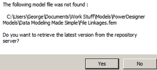
If you double-click a model shortcut in your workspace and the file does not exist in the expected location, PowerDesigner will ask you for help. If the file exists in the repository, it will display the options shown in Figure 10.80, giving you the option of retrieving the model or file from the repository. If you choose not to do that, or the model is not in the repository, PowerDesigner will display the options shown in Figure 10.81. Click on <Yes>, and then browse your folders to find the model. If it really is missing, all may not be lost – rename and open the backup file that PowerDesigner created for you.
Figure 10.80 File not found 1st option
| Figure 10.81 File not found 2nd option
|

When a model contains links to other models, PowerDesigner refers to those ‘other’ models as ‘Target Models’. When you have a model open, select Target Models on the Tools menu to see a list of target models. You can edit this yourself, if you know the new location of the file.
When you open a model, PowerDesigner checks this list of target models. If a target model file was renamed or moved, PowerDesigner will attempt to find the model itself, using the model GUID. Sometimes it will ask for confirmation with a message similar to that in Figure 10.82. In this case, the filename for the target model was changed – just click <Yes> to link to the new file name.
Figure 10.82 An unresolved target model

If you delete an entry from the list of target models, every link to that model will be removed – this can include shortcuts, replicas, generation links, and traceability links.
Absolute vs. Relative File Shortcuts
This is a dry topic for a data modeling book, so please bear with us. You may never need to understand this topic, but it may help you to understand what happens when PowerDesigner cannot find a file.
There are two types of file shortcuts maintained by PowerDesigner, absolute and relative.
Absolute | The shortcut describes the exact location of the file, such as C:UsersFredDocumentsModelsMy ProjectMy LDM.ldm. If you move or rename My LDM.ldm, PowerDesigner will not be able to find it. |
Relative | The shortcut describes the location of the file, relative to the location of the current file. The simplest form of relative shortcut just provides a filename – the file is assumed to be in the same folder as the current file. |
Figure 10.83 shows the potential links between files in PowerDesigner, and the type of shortcut used for each one.
Figure 10.83 File shortcuts

 A few simple conclusions can be drawn from Figure 10.83. Follow these and your life will be easier:
· Always use projects to manage related models, and never move individual project files – always move the entire project
· Always keep project files in the project directory
· Keep your models in a dedicated folder structure, with one folder for each project.
Partitioning a Model
Dividing a large model into manageable chunks is a common feature of data modeling tools; they may be called submodels, subject areas, packages, etc. In PowerDesigner, you can divide a model using packages.
Packages
A package is a subset of a model. When working with large models, you can split them into smaller subdivisions to avoid manipulating the entire model at once. Packages can be used to organize your model into different tasks and subject areas, and to assign parts of it to different modelers.
You can create as many packages as you need in a model, just remember that every package name must be unique within the model. You can create packages within packages – there is no limitation to the number of package layers.
Packages can contain the same kinds of items as models:
· Model objects
· Other packages
· Diagrams.
Each package has its own default diagram, which will always be present. This is demonstrated by Figure 10.84, which shows the Browser view of an LDM called ‘Chapter 5’, created to provide images for this book. The highlighted entry (Figure 5.20) is a package: packages are always shown at the top of the content of a model or parent package. The model also contains two diagrams (called Figure 5.19 and Figure 5.70) and several entities. One of the entity entries (Member) has a shortcut symbol in the corner of the icon – this tells you that this entity is a shortcut to an object held elsewhere. Figure 10.85 shows what happens when you include this entity in a model diagram - the entity symbol includes a shortcut arrow to indicate that the object is a shortcut, and the name of the package (Figure 5.20) to which the entity belongs.
By default, a package uses the parent namespace – the names of objects within the package must be unique in the model. The Use parent namespace property on the ‘General’ tab of the property sheet allows you to override this behavior – unchecking this option allows the objects in the package to have the same name as objects elsewhere in the model.
Figure 10.84 A package example
| Figure 10.85 Shortcut to a package entity
|


You can right-click the package name in the Browser to view lists of objects in the package and sub-packages, in the same way as you can for the full model.
When to use Packages in Data Models
· To group entities by subject area
· To manage access privileges in the repository
· To hold shortcuts to objects created outside the model – these shortcuts are added to the model when you add traceability links
· To hold objects that you do not want to have generated into new models – this is useful in a PDM, where you want to retain (but not generate) tables that have been denormalized via transformations.
![]() “Packages” (Core Features Guide)
“Packages” (Core Features Guide)![]() “Converting a Diagram to a Package” (Core Features Guide)
“Converting a Diagram to a Package” (Core Features Guide)![]() “Moving a Diagram to a Package” (Core Features Guide)
“Moving a Diagram to a Package” (Core Features Guide)![]() “Moving Entities Between Packages in a CDM” (Core Features Guide)
“Moving Entities Between Packages in a CDM” (Core Features Guide)
Model Extensions
We have mentioned model extensions a few times. PowerDesigner uses extensions to provide new objects, additional properties for objects, new connections between objects, and changes to the standard property sheets. If you add a new property to an entity for example, a new extension is automatically created in the model. Extensions are visible in the Browser. Figure 10.86 shows a model with three extensions. The two with a shortcut symbol in their icon are shortcuts to extension files – these are files containing common extensions. The third extension (Entity properties) exists within the model, not in an external file.
You will create your own local extension in Exercise 18. Also see Chapter 23 for more on extensions.
Figure 10.86 Extensions in the Browser

Attaching Extensions to an Existing Model
- Select Model|Extensions to open the List of Extensions.
- Click the ‘Import’ tool
 to open the Select Extensions dialog.
 - Review the different types of extensions available by clicking on the sub-tabs, and then select one or more to attach to your model.
· Ensure that you open the property sheet for the extension and read the Comment property, which will provide guidance on how to get the best out of the extension
· For example, the Comment property for the extension Relationship Assertion with Plural Entity Names lists four steps you must follow in order for the extension to be effective within a model:
1. Select Tools|Model Options|Assertion template.
2. Select this extension file in the Assertion Extension list.
3. Replace the standard template in the main text box with the following call to the plural template: %pluralAssertion%
4. Click <OK> to save your changes.
Finding Things Again
Have you lost an entity? Do you want a list of entities with no Description?
You need to run ‘Find Objects’. There are three ways to do this:
· Search local models that are currently open
· Search the repository – this provides the same features as a local search, but you can search all the models you have access to
· Search via the PowerDesigner web portal – this searches the repository, and provides more comprehensive capabilities, and the ability to save search criteria.
Searching Local Models
Look on the Edit menu, or press <Ctrl+F>. The Find Objects dialog is shown in Figure 10.87.
Figure 10.87 Finding objects

You can search the workspace, a folder, a project, or a model, and you can supply an expression for name searches. The first tab shown in Figure 10.87 shows a search for objects called ‘division’. The second tab shows that we can specify additional criteria: in this case, we’re looking for objects with an empty description.
The results of a search are displayed in the ‘Result lists’ window; you can see a sample in Figure 10.88.
Figure 10.88 Search results

A summary of the search results is also shown in the ‘General’ tab on the ‘Output’ window.
Our search found two entities and a shortcut to an entity. We can access any of these objects: double-clicking will open the property sheet, and right-clicking on the name will display the contextual menu, which will allow us to find the object in the Browser or diagram, carry out an impact analysis, open the object’s property sheet, or clear the results list. We can also copy an entity to the clipboard or delete it.
The result list stays in place until we clear it, hide it, run another search, or shut down PowerDesigner.
Remember that you can use the View toolbar to hide and display the Result list.
Searching the Repository
To search the repository, select Find Objects on the Repository menu, or press <Ctrl+Alt+F>. The repository search works in the same way as the local search, except that the ‘Glossary’ options have been replaced with options regarding ‘Repository Dates’.
Searching via the Web Portal
The portal provides a quick search facility, which allows you to search for uses of textual terms. The advanced search facility allows you to specify more complicated and multiple search criteria.
After performing a search, you can:
· generate an Excel or PDF version of your results
· search within your results
· modify your search string
· make your search available for reuse.
| Unless your search has a very narrow focus, or you only need to search models you have not checked in, you should always search the repository. You will have more success, as it will search every model you have access to. |
| “Finding Objects” (Core Features Guide) |
YOUR TURN TO PLAY
- Open the three Project Management models, and then press <Ctrl+F> to open the Find Objects dialog.
2. Take a look at the tabs, and then come back to the ‘Name & Location’ tab’.
3. In ‘Look In’, select the Workspace option.
4. In ‘Model type’, select ‘Any type of model’.
5. Type the following into ‘Name’ - *employee*.
6. Click on ‘Find Now’.
7. Open the ‘General’ tab on the ‘Output window’ to see a summary of the search results; right-click the summary, and select ‘Clear’.
8. Open the ‘Result List’ window to see the detailed search results. This looks a lot like a list of objects, although it contains more than one type of object, and the results cannot be filtered. However, you can sort the list by clicking on the column headings.
9. Right-click any object in the list to access a contextual menu. This shows options you’ve seen before except for the ‘Clear’ option, which will clear the contents of the Result list.
10. Double-click any column in the list to open the property sheet.
11. Click on the ‘Property Sheet Menu’ (to the right of the ‘Less’ or ‘More’ button), and select ‘Parent Properties’ to open the property sheet for the table that contains the column. See Figure 10.89.
Figure 10.89 Accessing parent properties

12. Click on the ‘Property Sheet Menu’ in the property sheet for the table, to open the property sheet for the model.
13. Close the property sheets.
EXERCISE 8: Creating your own Workspace, Project and Models
This is your first exercise using PowerDesigner, so we’ll guide you through what you need to do.
Here’s a summary of what you’re going to do:
1. Open the Demo workspace, and save two of the Demo models as new files
2. Create a new workspace for exercises, called ‘Exercises’
3. Create a folder and project in the Exercises workspace, both called ‘Exercise 8’, then bring the copies of the Demo models into your project and look at the project diagram
4. Move the files into your Project directory, and look again at the project diagram
5. Create a new Free Model with the ‘Excel Import’ extension attached, and then detach it from the workspace
6. Create a new CDM, copy several entities across from the existing CDM, create shortcuts to several others, and then look again at the project diagram
7. Create a new diagram in the new CDM, and add selected entities
8. Rename or delete several items via the Browser, then add missing relationships
9. Decorate the diagram with notes and other symbols
10. Change the appearance and layout of the project diagram
11. Use Windows Explorer to see the files in the project directory
12. Close and save the workspace.
Start PowerDesigner, and you are ready to begin.
1. Open the Demo workspace, and save two of the Demo models as new files
Use Windows Explorer to create a new folder called ‘Exercises’, wherever you intend to keep your PowerDesigner models.
Open the Sybase Demo workspace that we’ve looked at before. If you still have the Welcome screen in front of you, select ‘demo.sws’ from the list of recent projects and workspaces. If you hover the mouse over the name, the tooltip will tell you which folder it’s in. You can also see the same list of recent projects and workspaces via the File menu. Select Recent Workspaces and Projects, and the Demo workspace will be near or at the top of the list.
Open the model called ‘Project Management (CDM)’, right-click the model name, and choose Save As. Save the model in your new folder, and call it ‘Exercise 8.cdm’. Do the same with the model ‘Project Management (LDM)’, calling it ‘Exercise 8.ldm’.
Now close the Demo workspace without saving any models. Don’t worry, your new files will be OK, you’ve already saved them.
2. Create a new workspace for exercises, called ‘Exercises’
You now have an empty workspace displayed. Use File|Open to open the two new models. If you’re following these steps, the ‘Exercises’ folder is the last place in which PowerDesigner saved anything, so it’s the suggested location for opening models.
PowerDesigner has a very small memory for folders; it only remembers the last place you saved ‘something’. It is up to you to remember where your models are. Remember that you can see lists of recent files, projects, and workspaces via the File menu.
In the File menu, select Save Workspace, and save it in the ‘Exercises’ folder. Call it ‘Exercises.sws’.
3. Create a folder and project in the ‘Exercises’ workspace, both called ‘Exercise 8’, then bring the copies of the Demo models into your project and look at the project diagram
In the Browser, right-click the word ‘Workspace’, select New, and then Folder. Type ‘Exercise 8’ and press <OK>. In the File menu, select New Project, and then type ‘Exercise 8’. Make sure that the Location property contains the path to your ‘Exercises’ folder, and that ‘Append name to Location’ is selected. Now press <OK>. You should now have two models at the top level of the workspace, along with a folder, which contains a project. The drawing Canvas will be blank, as it shows an empty project diagram.
In the Browser, select both of the models, and drag them onto the project name. They will move into the hierarchy below the project, and icons for them will appear on the project diagram. They will be connected by a line labeled ‘Generation’, reflecting the fact that the LDM was generated from the CDM. Notice that both model icons have a shortcut arrow on them because the files are stored outside the project directory.
4. Move the files into your Project directory, and look again at the project diagram
Select one of the models, right-click the mouse, and then select Move to Project Directory. Do the same with the other model. In the Window menu, select the entry starting with ‘PRJ Exercise 8’, to bring the project diagram to the front. You’ll see that the shortcut arrows have been removed from the icons. At this point, it is a good idea to click the ‘Save All’ button on the ‘Standard’ toolbar. This will save all the models, the project, and the workspace.
5. Create a new Free Model, with the ‘Excel Import’ extension attached, and then detach it from the workspace
In the Browser, select the ‘Exercise 8’ folder, and then click on the ‘New Model’ button on the ‘Standard’ toolbar. The window you can now see allows you to create any type of model. Select ‘Free Model’, and call it anything you like, because we’re not going to keep it. Before you click on <OK>, click on the ‘Select Extensions’ button near the bottom right corner. The ‘Select Extensions’ window allows you to select extensions to PowerDesigner; select any or all of them that sound interesting, then click on <OK>, and <OK>, again. The Browser folder will contain a new Free Model, and the default diagram will be open on the Canvas.
As the name suggests, Extensions provide the ability to extend or alter PowerDesigner’s capabilities. We’ll tell you more about this later, but please don’t expect a detailed tutorial!
Let’s assume that we did this by mistake, and we don’t want to keep this model. Because we haven’t saved it yet, we can just remove it from the workspace. Right-click the model name in the Browser, and select ‘Detach from ‘Workspace’. PowerDesigner will ask if you want to save it, so click on ‘No’; the model is gone from the workspace. Selecting the model name and pressing <Delete> will also do the trick.
6. Create a new CDM, copy several entities across from the existing CDM, create shortcuts to several others, and then look again at the project diagram
Right-click the project, select ‘New’, and create a Conceptual Data Model called ‘Exercise 8 Employee’. Make sure you select both of the available extensions.
In the ‘Project Management (CDM)’ model, open the ‘Main diagram’, and select the following entities, along with all the relationships connecting them. The <Shift> key will be useful here:
Entities: Division, Employee, Team.
Hold down the <Ctrl> key, drag the selection into the Browser, and drop it onto the name of the CDM you created. The entities will be copied into the new model, and should still exist in ‘Project Management (CDM)’. If they have been removed from ‘Project Management (CDM)’, you forgot to hold down <Ctrl>. Use the Undo tool  to undo the changes, and try again.
In the ‘Project Management (CDM)’ model, select the following entities in the Browser, then copy them using the main menu, contextual menu, or keyboard shortcuts:
Entities: Activity, Customer.
Now right-click the name of the CDM you created, select Edit and Paste As Shortcut.
The new CDM will now contain five entities, two of which are shortcuts to the original CDM. It should look something like Figure 10.90.
Figure 10.90 Five entities, so far

Now click on the ‘Save All’ button. PowerDesigner will ask if you want to save the unsaved models; click ‘Yes’, and then click ‘Save’ to save the new CDM with the default file name (which is the same as the model name).
7. Create a new diagram in the new CDM, and add selected entities
Right-click the name of the new CDM, select New, then Conceptual Diagram. Call the diagram ‘Exercise 8’, and select ‘Default Diagram’. Click on <OK>.
Select the Division, Employee, and Team entities in the Browser, and drag them onto the new diagram. The entities will appear on the diagram, but not the relationships, although the relationships do appear in the Browser. We’ll get back to them in a minute.
8. Rename or delete several items via the Browser, then add missing relationships
The content and style of the entities will be the PowerDesigner default, unless you have saved any of your previous Display Preferences as the default. Press the <F8> key to center the model in the Canvas, then press <F6> to zoom in (and <F7> to zoom out), as many times as you need for the entity symbols to be a good size to work with.
Select the Employee entity in the diagram and click on the name. It should turn into an ‘edit box’, allowing you to retype the name. Change the name to Old Entity; the entity name will change in the Browser as well. Now change the name back to Employee, this time using the Browser.
In the Browser, select ‘Diagram_1’ in the CDM you created. Press <Delete>, and click on <Yes> when you’re asked if you’re sure.
Now select the Activity entity, and then press <Delete>. Don’t click on <Yes> or <No> just yet, click on the <Impact…> button. This opens up the ‘Impact and Lineage Analysis’ window, using the standard ‘delete’ rule set. If you want to see the properties of the entity to which this is a shortcut, double-click where it says “Shortcut ‘Activity’ [Delete]”, and the property sheet will be opened. Close the impact analysis window, and click ‘No’ to deleting the entity.
Select the Activity and Customer entities, and drag them onto the ‘Exercise 8’ diagram. They are shortcuts to entities in a different model, so the symbols include the shortcut symbol in the corner.
The relationships are still missing from the diagram, and there are two ways to include them. First, the Show Symbols command is on the Symbol menu and on the diagram contextual menu, within Diagram. Run the command, and you will see a screen containing three tabs that allow you to select any of the entities, relationships, or diagrams in the model. That’s right, a diagram can contain a shortcut to another diagram, even a diagram in a different model.
It is possible to add entities to the diagram this way by accident, by including a relationship that involves an entity that you do not have on the diagram.
The quickest and best way to include missing relationships is to use the ‘Complete Links’ command. You can access this via a button on the ‘Diagram’ toolbar, the Tools menu, or by pressing <Ctrl+F5>. With this method, you cannot choose what will or will not be included on the diagram, but you do not have to work out what is missing. PowerDesigner will add every relationship that should be on the diagram because both of the participating entities appear on the diagram.
Run ‘Complete Links’ whichever way you prefer, to add the missing relationships. Experiment with the options on the ‘Layout’ toolbar or the symbol menu to create a tidy diagram. There are only three relationships, so it will not take long.
Click on the ‘Save All’ button.
9. Decorate the diagram with notes and other symbols
Carry on working in the diagram called ‘Exercise 8’.
Select the Title tool ![]() in the Free Symbols palette in the Toolbox, and draw a title box. Press the right mouse button to return to the arrow pointer, then right-click the title box and select Format – change the line style and font to make the Title stand out better.
in the Free Symbols palette in the Toolbox, and draw a title box. Press the right mouse button to return to the arrow pointer, then right-click the title box and select Format – change the line style and font to make the Title stand out better.
Now double-click the Title box – the property sheet for the model will open. By default, the ‘General’ and ‘Notes’ tabs are available. Click on the <More> button to display all the tabs. The model has a standard set of tabs, just like other objects.
Click on the ‘Related Diagrams’ tab and click on the Add Objects tool  to display the ‘Add Objects’ dialog, as shown in Figure 10.91.
Figure 10.91 Add objects dialog

This allows you to select any diagram(s) in any project or model that is currently open. Select the Exercise 8 Project diagram and click <OK>. PowerDesigner will create a dependency between the CDM and the Project Diagram. This is visible on the ‘Related Diagrams’ tab of the CDM’s property sheet, and on the ‘Dependencies’ tab of the project diagram’s property sheet. To see the dependency, right-click the project diagram in the Browser, select Properties from the contextual menu, and then select the ‘Dependencies’ tab.
Select the ‘Rectangle’ tool on the ‘Free Symbols’ palette, and draw a rectangle on the diagram – make sure that two of your entities are completely inside the rectangle. Change the cursor back to the standard arrow pointer. Double-click the rectangle to open the Text window, and select the ‘RTF’ radio button. Select the Format tool  , and change the default font style and size; now type a label for the rectangle, and press <OK>. The label will appear inside the rectangle – the exact position will depend on the display preferences.
Try out the ordering of symbols. From the rectangle’s contextual menu, select Order|Bring to Front – it will obscure everything that falls within its borders. Now do it again, this time selecting Send to Back. Finally, select Format from the Contextual Menu, change the Line and Fill colors to any colors you like, and the Text Alignment to ‘Left’ and ‘Top’, and press <OK>. If you want to, you can change the font.
Now use the ‘Note’ tool on the ‘Predefined Symbols’ palette to draw a Note symbol; change the cursor back to the standard arrow pointer, right-click the rectangle symbol, and select Get Format from the contextual menu. Select Apply Format on the contextual menu for the Note symbol. The Note will now have the same format as the rectangle. The result should look something like Figure 10.92.
Figure 10.92 Apply format

Select the Link/Traceability Link tool  on the ‘Free Symbols’ palette, and draw a link from the Note to one of the entities inside the rectangle. Part of the line is behind the rectangle, so use the contextual menu for the link to bring the link to the front. Double-click the link – the text box you see here is similar to the text box for the rectangle, except that it allows you to specify up to three blocks of text, each of which will appear at a different point on the line.
Finally, on the contextual menu for the note, select ‘Change Image’. The ‘Select Image’ dialog (see Figure 10.93) allows you to choose another image for the symbol. Browse the options available, and choose a symbol.
Most of the images available will obscure any text you may have added to the note.
Figure 10.93 Change the image
10. Change the appearance and layout of the project diagram
On the Window menu, select Close All to tidy things up. Open the Project diagram called ‘Diagram_1’, and run ‘Show Symbols’ to include your new CDM.
The ‘Model’ icon has been added to the diagram, along with a link to ‘Project Management (CDM)’, labeled ‘Reference’. If you double-click the line, it will open the property sheet for the link – click on the ‘Dependencies’ tab to see details of the objects . You may need to click on ‘More >>’ to make the tab visible.
If the original CDM is open, you will see a list of the entities you copied across as shortcuts. You can double-click the entities, and open their property sheets. If your original CDM is closed, you will only see the name of the project diagram here.
Please close any open property sheets.
Now for some quick cosmetic changes. Select all symbols on the diagram, and then press <Ctrl+Q>. The model icons are replaced with boxes. Now select Auto-Layout on the Symbol menu, and select the ‘Hierarchical’ layout, with ‘Top to Bottom’ orientation. You may also want to click on <Set as Default> to save your choice as the default layout for that type of diagram. When you click on <OK>, the diagram will be re-drawn as a vertical hierarchy.
11. Use Windows Explorer to see the files in the project directory
Use Windows Explorer to open the folder you created in step 1. It should contain a folder called ‘Exercise 8’, and the workspace file (Exercises.sws). Open the folder ‘Exercise 8’: this is what PowerDesigner calls the Project Directory. It will contain the project file (Exercise 8.prj), and three model files (two CDMs and one LDM). It will also contain backup files that Power Designer has created,
12. Close and save the workspace
Close the workspace, making sure to save all the models.
See the Appendix for the final CDM and project diagrams.
· The interface can be as cluttered or uncluttered as you want it to be. · Contextual menus are available everywhere. · Menu options depend on the current diagram on the canvas. · Object property sheets allow you to do much more than just edit a single object. · Common sorting, selection and filtering functions in any list of objects or sub-objects. · Save frequently - don't forget that you can still undo. · An object can have many symbols, sometimes more than one on a diagram. · Let PowerDesigner route your links for you. · Add relationships and other objects to diagrams using 'show symbols'. · Decorate diagrams and customize symbol images and content to aid communication. · Workspaces and projects are essential tools for managing multiple models. · Search via the repository for best results. |