CHAPTER 12
How do I create data elements in PowerDesigner?
Data Items, Terms
Domains, Attributes, Columns
Elementary!
The level of support provided for data elements by data modeling tools can be summarized in the following categories.
Category | Attribute | Column | Domain | Elementary Data Item |
|---|---|---|---|---|
Minimal | - | ü | - | - |
Useful | ü | ü | - | - |
Essential | ü | ü | ü | - |
Comprehensive | ü | ü | ü | ü |
Minimal support only allows you to model databases; that’s a start, but there’s a lot more to data modeling than databases.
Useful support allows you to create logical data models as well as model databases, but doesn’t provide Domains to help you manage data element characteristics.
Essential support allows you to use Domains to manage the consistency of data types and values of reference data.
Tools that fall into the Comprehensive category provide a key additional feature, the ability to record facts or definitions of data independently of entities. This is a key benefit for business and data analysts, and for the organization as a whole – finally, we can describe our data in business terms without modeling first!
The level of support that PowerDesigner provides for data elements is beyond the Comprehensive level: the Glossary features introduced in PowerDesigner 16 allow us to record the vocabulary of the business as Terms, and to use those Terms as the basis of a naming standard for data elements and other objects.
We discuss the different types of data models in Section IV, so we don’t provide too much detail here. It’s sufficient for now to say that data elements play a vital role in all three types of data models that PowerDesigner provides, the Conceptual, the Logical, and the Physical Data Models.
Data Items, Attributes, and Columns are all data elements, just as we outlined in Chapter 4. There are key differences between them due to the context in which they’re used, which we’ll discover later; it’s what they have in common that we’re interested in here.
In PowerDesigner, the ‘Elementary Data Item’ is known as a Data Item; a Data Item is a ‘conceptual’ data element, independent of any model objects such as entities. They are integral to the Conceptual Data Model, where every attribute automatically references an underlying Data Item.
An Attribute defines a data element within the context of an Entity in a Conceptual or Logical Data Model, whereas a Column defines a data element within the context of a Table in a Physical Data Model.
All the PowerDesigner data models allow you to define Domains to manage the characteristics of your data elements.
In this chapter, we will outline a simple strategy for how and when to use each of the types of Data Elements in PowerDesigner, as well as introduce you to the PowerDesigner Glossary.
Table 12.1 illustrates the types of Data Elements in PowerDesigner. The arrows show the ‘generation’ links that are created as you transform one type of model into another type of model. We’ll discuss this topic more in Chapter 18. For now, we’ll just say that the Conceptual, Logical, and Physical Data Models can form a chain of linked models. We create that chain by generating one model from another, thereby also creating a chain of related data elements. You can create each of the models manually, and manually map them to each other if you choose to, but letting PowerDesigner do that work for you will deliver better results.
Table 12.1 Data elements and generation links
| Type of Data Model | ||
|---|---|---|---|
Type of Object | Conceptual | Logical | Physical |
Data Item | ü |
| |
Domain |
|
| ü |
Attribute |
|
|
|
Column |
| ü | |


Domains are transferred from the Conceptual model to the Logical model, and then to the Physical model. Attributes are transferred from the Conceptual model to the Logical model, and then converted into Columns in the Physical model. As we’ll see in Chapter 18, it’s also possible to generate a Physical Data Model directly from a Conceptual Data Model, and vice versa.
Table 12.1 shows the standard “top-down” generation links. In reality, the possibilities are more complex; PowerDesigner also allows you to work “bottom-up”, generating a Logical Data Model from a Physical Data model, and a Conceptual Data Model from a Logical Data Model. You can also generate a new model of the same type as the original.
Properties are transferred between data elements when we generate the chain of data elements we referred to earlier. “Transferring Properties”, later in this chapter, will provide you with more details.
There are differences in the support for Attributes in Conceptual and Logical Data Models, so to avoid confusion, we will use the following phrases when referring to Attributes:
an attribute in a Conceptual Data Model | |
Logical Attribute | an attribute in a Logical Data Model |
Attribute | an attribute in either type of model |
Standard Properties for Data Elements
 In addition to the “common” properties described in Chapter 10, there are standard properties shared by all the types of data elements in PowerDesigner, shown in Table 12.2.
Table 12.2 Standard data element properties
Data type, length, and precision | Data type specifies the nature of the data, such as character, numeric, or date. The length is the number of characters or digits the data element will allow. The precision applies to numeric data, and specifies the number of possible digits after the decimal point. The precision is NOT part of the length; if you need to represent the number 1234.56, the Length must be set to ‘4’, and the Precision must be set to ‘2’. If your DBMS supports them, you can define your own Abstract Data Types in Physical Data Models.
|
Check parameters | PowerDesigner allows you to define constraints to control the range and format of data. You can specify constraints on the ‘Standard Checks’ and ‘Additional Checks’ tabs. See “Managing Allowable Values” and “Exporting and Importing Lists of Values”. You can create data formats to reuse in constraints for multiple objects by clicking the New button to the right of the Format field on the ‘Standard Checks’ tab. Data formats are informational only. |
Mandatory property | Specifies whether or not a value must be assigned when we create an instance of the object containing this data. |
![]() “Attribute Properties” (Data Modeling)
“Attribute Properties” (Data Modeling) ![]() “Column Properties” (Data Modeling)
“Column Properties” (Data Modeling) ![]() “Data Item Properties” (Data Modeling)
“Data Item Properties” (Data Modeling) ![]() “Domain Properties” (Data Modeling)
“Domain Properties” (Data Modeling)![]()
 “Creating Data Formats for Reuse” (Data Modeling)
In the next section, we’ll show you where to find all of these properties in a Domain; the instructions also apply to other types of data elements. These properties can be transmitted from data element to data element; see “Transferring Properties”, later in this chapter, for more information.
Domains in PowerDesigner
In PowerDesigner, Domains help you to standardize data characteristics within your Data Items, Attributes, and Columns. We will let you explore Domains for yourself by creating several Domains in a Conceptual Data Model. Before you do that, though, take a look at Figure 12.1, which shows all the tabs on the property sheet for a domain.
Figure 12.1 Domain properties – all tabs

YOUR TURN TO PLAY
- Open the workspace you created in Exercise 8, and create a new top-level folder called ‘Chapter 12’. Now create a new Conceptual Data Model by clicking on the ‘New Model’ option on the ‘File’ menu. Call the model ‘Chapter 12’. You should have ‘Diagram_1’ open on the Canvas. Rename it to ‘Chapter 12 CDM’.
- Now save the model in the ‘Exercises’ folder.
- We will not be using the diagram in this exercise, but do not close the diagram, or we will not have the correct menu options displayed.
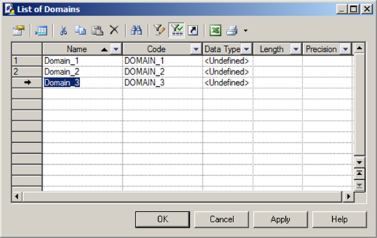
- Click on the ‘Model’ menu, and then select ‘Domains’. An empty list of domains is displayed; you need to create three domains, so click on the add a row tool
 three times. The result is shown in Figure 12.2.
Figure 12.2 List of domains
5. Overtype the three domain names with the following, in any sequence, and click on <Apply>:
· Date
· Person Name
· Order Status Code.
 Remember – you can easily move between the items in the list using the cursor (arrow) keys.
The ‘Domains’ folder, containing three new entries, now appears in the Browser.
6. We’ll continue to work in the list of domains for a while. Click on the ‘Data Type’ entry for the ‘Date’ domain, and select ‘Date’ from the drop down list of values. Click on the ‘Data Type’ entry for ‘Order Status Code’; Figure 12.3 shows the result.
Figure 12.3 Our three domains

7. Now click on the tool with three dots on it, in the ‘Data Type’ column; this opens a simple dialog (see Figure 12.4) which allows you to choose one of the standard data types, then specify the length and precision, where appropriate.
Figure 12.4 Standard data types

8. Set the Data Type for Order Status Code to ‘Number’, and the Length to ‘2’, then click <OK>. At this point, the domain details have been updated in the list of domains, but the changes have not been applied to the model, so click on <Apply>.
If you press the <Esc> key, all unapplied changes will be ignored.
9. Now, double-click the row number or arrow to the left of ‘Person Name’. The property sheet for the domain will open. You should see the contents of the ‘General’ tab displayed. If a different tab appears, that is because you selected ‘Keep Last Tab’ in the General Options (see Figure 11.4).
10. In the ‘General’ tab, select the data type ‘Characters (%)’, and set the length to 120. Select the ‘Mandatory’ check box, which will force all data elements attached to this domain to be mandatory. Click <OK> to close the property sheet, and then click <OK> to close the Domain List.
11. It would be wise to save the model at this point.
12. Now it’s time to add definitions to our domains. Open each domain, in turn, via the Browser or the list of Domains, whichever you prefer. For each Domain, enter the descriptions from Table 12.3 into the Description property in the ‘Notes’ tab.
Table 12.3 Domain descriptions
Domain | Description |
Date | The standard Date Domain for XYZ Inc. This must be utilized for all Dates for which a more specialized Domain does not exist. |
Order Status Code | A code that identifies a valid overall status of an Order. It is updated as a result of actions carried out relating to the whole Order, or against individual Order Lines within the Order. |
Person Name | The standard format for a defined part of a Person’s name, such as ‘Person First Name’ or ‘Person Family Name’. |
13. We have some values we need to add to ‘Order Status Code’, so open the domain again, and then select the ‘Standard Checks’ tab. Type the values shown in Table 12.4 into the List of Values property.
Table 12.4 Values for Order Status Code
Value | Label |
01 | Open |
02 | Shipped |
03 | Closed |
04 | Returned |
14. Check the ‘Complete’ check box to indicate that there are no missing values.
15.  If your list of values is in a table in a spreadsheet or document, you may copy and paste them into the ‘List of Values’ only if there is at least one value already in the List. Here’s how to do it:
· Ensure your values are in two columns – Value and Label. The first row is assumed to contain labels
· Select any existing value in the list of values in the Domain by clicking on the row number; if you paste into an empty list, only the first value is pasted
· Paste, using <Ctrl+V> or the ‘Paste’ button on the list of values toolbar.
· Your values are appended to the existing values.
PowerDesigner prevents you from entering duplicate values in the list by suffixing the duplicate value with a number.
 PowerDesigner does NOT check whether your values match the Domain data type.
16. Now let’s create another Domain that is similar to an existing domain. In the Browser, select the Domain ‘Order Status Code’, and then press <Ctrl+C> to copy the Domain into the Clipboard. Select the ‘Domains’ folder in the Browser, and press <Ctrl+V>; the Domain will be pasted from the Clipboard into a new Domain called ‘Order Status Code2’.
Copy and Paste works in the Browser – you can even copy and paste between several models, provided they are the same type of model. To copy objects between models of different types, you need to use the generation capabilities – see Chapter 18.
17. Now we need to edit the new Domain. Click on the Domain Order Status Code2 in the Browser, then either press <F2> or click on the name again, to enable name editing. Change the name to ‘Order Line Status Code’, and press <Enter>.
18. Double-click ‘Order Line Status Code’ in the Browser to open the property sheet. The properties we need to change are the description and the values. In the ‘Standard Checks’ tab, add one further value:
05 Cancelled
19. In the ‘Notes’ tab, provide the following Description, then click on <OK>:
‘A code that identifies a valid status for an Order Line.’
Figure 12.5 shows the list of Domains with the four domains.
Figure 12.5 Our four domains

Enforcing Non-divergence from a Domain in a Data Model
Domains help you to standardize data characteristics within your Data Items, Attributes, and Columns. In the following paragraphs, we refer to these collectively as ‘Data Elements’.
The Model Options allow you to decide which properties are to be enforced. On the Tools menu, select Model Options. Figure 12.6 shows the default options relating to Domains.
Figure 12.6 Data model options for domains

Select the check boxes of the data element properties that are not permitted to diverge from the domain definition. You can specify any or all of:
Data type | data type, length, and precision |
Check | check parameters such as minimum and maximum values |
Rules | business rules |
Mandatory | mandatory property of the attribute or column |
[PDM only] Profile | test data profile |
Which properties you enforce will depend on how you’re using Domains. If you use them to manage lists of values, then you’ll need to select ‘Check’ to prevent the creation of multiple lists of values for the same data.
If you subsequently modify any of a domain’s properties specified here as non-divergent, the corresponding properties of the Data Elements attached to that domain will be updated automatically.
Properties specified as non-divergent appear dimmed and are non-editable in Lists and Data Element property sheets. If you want to modify a non-divergent property, you must detach the Data Element from its domain, or change the divergence properties for the domain.
When you set the ‘Enforce non-divergence’ options, you are asked if you want to apply domain properties to Data Elements currently attached to the domain. If you click <OK>, the Data Element properties are modified to be consistent with the properties of the domain to which they belong. See the ‘Dependencies’ tab on the Domain property sheet to see the linked Data Elements.
Whenever you amend a Domain, PowerDesigner checks to see whether any Data Elements use the Domain. If so, an update confirmation box (see Figure 12.7) is displayed, asking if you want to cascade the domain changes. Remember, changes to Domains could be cascaded to a whole chain of data elements in many models, so it is wise to check the impact analysis before making changes.
Figure 12.7 Cascading domain changes

The ‘Check’, ‘Rules’, and ‘Mandatory’ boxes should be selected only if those properties have been amended. In Figure 12.7, the ‘Data Type’ check box cannot be amended, because we have (via the model options) decided to enforce the data type for all Domains.
When you check a model, any differences between Domains and the objects attached to them are reported. See “Compare and Merge” in Chapter 23.
The Result of our Edits
Figures 12.8 to 12.10 show the key tabs for one of our domains, “Order Status Code”.
Figure 12.8 Order Status Code – ‘General’ tab

Note the  tool to the right of Data Type; this opens the ‘Standard Data Types’ selection window you saw in Figure 12.4.
Figure 12.9 Order Status Code – ‘Standard Checks’ tab

Figure 12.10 Order Status Code – ‘Notes’ tab

In the next two sections, we will use these Domains in Data Items and Attributes, and come back to the other Domain tabs.
| “Domains (CDM/LDM/PDM)” (Data Modeling) |
Data Items in PowerDesigner
A Data Item is a ‘conceptual’ data element that exists independently of any model objects, such as Entities or Tables. Data Items are integral to the Conceptual Data Model, where every attribute automatically references an underlying Data Item. They are not present in the Logical Data Model or Physical Data Model. We do not usually start a paragraph with a gotcha, but we have to here, because there is a fundamental point about Data Items that will affect how you decide to use them.
In a Conceptual Data Model, an Attribute is a Data Item that has been included in an Entity. If you amend an Attribute, you amend the Data Item, and every other Attribute in the model that is based on that Data Item.
There are two approaches you can take to create a pairing of Data Item and Attribute; the approach you take depends on your policy regarding the use of Data Items. See “Should we reuse Data Items within a model?” later in this chapter.
Approach 1 Include an existing Data Item in an Entity to create an Attribute – this may result in a Data Item being referenced by more than one Attribute
Approach 2 Create a new Attribute in an Entity, without selecting a Data Item
Both approaches are supported by the ‘Attributes’ tab in the Entity property sheet, and we’ll try them both in the next section - see “Creating a Conceptual Attribute”.
Figure 12.11 Data Item Property sheet

Figure 12.11 shows the ‘General’ tab on the property sheet for a Data Item; you’ll see that it’s virtually identical to the property sheet for a Domain, shown in Figure 12.1. The difference here is that you cannot edit the Data Type. The Data Item references the ‘Date’ Domain, so it inherits the Data Type from that Domain, and the Model Options prevent us from overriding the inherited Data Type.
Controlling Uniqueness and Reuse of Data Items
By default, PowerDesigner allows you to use a Data Item to create more than one attribute. For example, you can define a Zip Code Data Item once, and reuse it in whichever entities contain addresses. If you then update the Data Item, your changes will simultaneously cascade to all the attributes that use it. Remember, all these attributes are identical.
You can change this behavior via the ‘Model Settings’ section of ‘Model Options’. Table 12.5 lists the options available, and their effect.
Table 12.5 Model options – reuse of data items
Option | When selected | When cleared |
Unique code | Each data item must have a unique code. If you try to select this option and some existing data items are already sharing a code, the following error will be displayed: “Unique Code option could not be selected because two data items have the same code: To be able to select the option, you must first assign unique codes to all data items. | Multiple data items can have the same code, and you differentiate them by the entities that use them. The entities are listed in the Used By column of the list of data items. Note: To make an item visible in a list, click the Customize Columns and Filter tool in the list toolbar, select the appropriate check box from the list of filter options displayed, and click <OK>. |
Allow reuse | One data item can be an attribute for multiple entities. | Each data item can be an attribute for only one entity. |
Should we reuse Data Items within a model?
Should we allow Data Items to be used by more than one entity in a single data model? Remember the 100% match between a Data Item and an Attribute. If we use a Data item in three entities, the three Attributes are identical; every property (including the name) is identical.
In Chapter 16, we discussed how to normalize a data model; in essence, we make sure that each item of data only appears once in a data model, in the ‘correct’ entity. This implies that multiple uses of a Data Item is wrong, and indicates that the modeler’s work is not complete. However, this is not necessarily true. As in so many aspects of data modeling, ‘it depends’.
Mostly, it depends on the type of model you’re creating. It is very likely that a Conceptual Data Model would not be fully normalized, so some duplication of attributes may be acceptable. The decision we really have to make is whether to allow identical attributes in different entities. It can be tempting to speed up the modeling process by reducing the time we spend describing our Attributes, and reusing Data Items certainly allows us to do that; however, it could easily result in generic descriptions that lead to confusion and misunderstandings. We must avoid that at all costs; see Chapter 6 for a discussion of the importance of names and definitions.
In Table 12.6, both attributes use the same Data Item. Because the Data Item has to describe two similar but different concepts, it has a generic description. The descriptions do not tell us enough about the attributes; they are not complete.
Table 12.6 Forcing attributes to be identical
Entity | Attribute Name (Data Item Name) | Description |
Customer Application | Birth Date | The date a Person was born. |
Employee | Birth Date | The date a Person was born. |
For Table 12.7, we changed our naming standard for attributes, and renamed the two attributes from Table 12.6. We now have two Data Items with descriptions that are specific to the use of the data.
Table 12.7 Resolving the differences
Entity | Attribute Name | Description |
Customer Application | Customer Application Birth Date | The date of birth of the Customer, according to information entered by the customer on their application. |
Employee | Employee Birth Date | The date of birth of the Employee, verified by sight of their birth certificate or passport when they commenced employment. |
A side effect of this approach is the longer name on each Data Item – they include the name of the entity. This makes the Data Items more useful as the core of a Data Dictionary. It is also a potential concern for models further down the line, as we’ll discuss in ‘Managing Object Names and Codes’ in Chapter 20.
When to Use Domains instead of Data Items
Let’s think again about managing the definition of a Zip Code. If you need all Zip Code attributes to have the same generic description, then you could define a Data Item called Zip Code. A better approach would be to provide a generic description of Zip Code as a Term in the Glossary, and define a Domain called Zip Code, to ensure that all Zip Codes use the same format and validation. If you use this approach, you will make effective use of domains, and the traceability that PowerDesigner provides along the chain of data elements:
Term (in the Glossary) àDomain àData Item àCDM Attribute àLDM Attribute àPDM Column.
This topic is discussed in more depth in Chapter 20 – see “Managing Names and Codes” and “The Lineage of Data Elements”. See also “Replica Data Items in one Model” later in this chapter.
Incorporating Data Items in Governance
Data Items can assist you with governing a single data model, or governing all your data models. They allow you to take advantage of previous analysis work by creating a ‘catalog’ of approved data definitions, waiting to be incorporated into your model(s); ‘Data Dictionary’ is a common name for such a catalog. You could extend the properties of Data Items to record Data Ownership, Approval Date and Status, and other organization-specific information.
Data Items allow you to manage your elementary data definitions. If you use PowerDesigner for Business Process Modeling, Data Items provide the link from your data models to the elementary Data objects referenced by your business processes. 
We recommend that you incorporate PowerDesigner Data Items into your data governance process. The strategy must be applied consistently, a corporate strategy that applies to all models; individual models shouldn’t follow different rules, or it will be impossible to integrate them in the future if that becomes necessary.
A catalog of Data Items is simple to import from Excel using the Excel Import Wizard. Alternatively, you can generate them from any type of PowerDesigner object by defining your own Object Generation. For example, you may want to create a Data Dictionary from a set of ‘Data’ in a Business Process Model.
We recommend that you clear ‘Allow reuse’ in the CDM model options, and select ‘Unique Code’.
To share a set of Data Items with other modelers, check the CDM into the Library folder in the Repository; this will automatically be pushed out to all repository users. Modelers reuse the Data Items by creating Replicas of the Data Items, in their own models. See “Replica Data Items”, later in this chapter. This shared CDM is also ideal for sharing standard domains.
![]() “Generating Model Objects” (Core Features Guide)
“Generating Model Objects” (Core Features Guide)
Model Checks
You can run the Model Check to validate your Data Items. These checks include identifying Data Items:
· That are not used
· That are used multiple times
· Whose name is not unique
· Whose code is not unique
· That does not match the referenced Domain.
You can also use a Dependency Matrix to list Data Items that are or are not being used, as we’ll see shortly.
![]() “Example: Building a Data Dictionary in a CDM” (Data Modeling)
“Example: Building a Data Dictionary in a CDM” (Data Modeling)
![]() “Data Item Checks” (Data Modeling)
“Data Item Checks” (Data Modeling)
Attributes and Columns in PowerDesigner
Attributes are present in both Conceptual and Logical Data Models; Physical Data Models have Columns. In this chapter, we focus on Attributes, but you can carry out the same tasks with Columns; you will have a chance to create your own Columns in Chapter 17.
Attributes are sub-objects; they can only exist within an entity. Like Data Items, they do not have symbols; unlike Data Items, you can display their properties on an Entity symbol, and edit them via the Entity symbol.
Figure 12.12 shows the ‘General’ tab on the property sheet for an attribute in a Conceptual Data Model; this attribute uses the data item shown in Figure 12.11. Compared to Figure 12.11, there are additional properties referencing the data item, and the entity that contains this attribute. Remember the 100% match between the data item and attribute; any changes you make here will also affect the data item.
If you want to, you can click any of the ‘Properties’ buttons  on the right hand side, to access the property sheet for the Entity, Data Item, or Domain. You can also create a new Domain with the ‘Create’ button
  , or open a selection window to choose a Domain with the ‘Select Object’ button
  .
.
 There is a property we haven’t seen before, called ‘Displayed’. If this is not checked, the attribute will not be shown on any entity symbols.
To prevent an attribute from being displayed on a particular symbol, see “Communicating Your Message” in Chapter 10.
Figure 12.12 Conceptual attribute

Creating a Conceptual Attribute
If you’ve decided that the concept of a Data Dictionary is a useful one, then we suggest you create Data Items before you create your Attributes. You can create a Data Item via the Browser or a List of Objects. You cannot create a Data Item on a diagram, as they do not have symbols.
· Select Model|Data Items to access the List of Data Items, and click the Add a Row tool 
or
· In the Browser, right-click the model or package, and select New|Data Item
or
· If you already have Data Items in the model, right-click the Data Items folder, then select New

You could just create attributes, and let the data items be created automatically, but, as we said earlier, this could result in duplicate data items. To avoid this, consider pre-loading candidate data items using the Excel Import feature. You’ll probably create most of your attributes in the ‘Attributes’ tab in the entity property sheet. You can create attributes using the same methods used to create entities via the Object List you saw in Figure 11.2. As attributes are sub-objects, there are extra tools on the Toolbar, shown in Figure 12.13, and described in Table 12.8.
Figure 12.13 The sub-objects Toolbar on a list

Table 12.8 describes the purpose of the four important extra tools in a Conceptual Data Model.
Table 12.8 Adding attributes to a conceptual entity
Icon | Tool Name | Action |
| Reuse Data Item | Opens a Selection window (see Figure 12.14) listing all the data items available in the model. Select one or more data items in the list and then click OK.
|
| Insert a Row (the arrow is in the middle of the icon) | Inserts a new attribute at the current position in the list of Attributes, and creates a new data item. If you have enabled the ‘Allow Reuse’ model option, the new data item can be reused as an attribute for other objects. If you have enabled the Allow Reuse and Unique Code model options, and you type the name of an existing data item, it will be reused. |
| Add a Row (the arrow is at the foot of the icon) | Appends a new attribute and creates a new data item. If you have enabled the Allow Reuse model option, the new data item can be reused as an attribute for other objects. If you have enabled the Allow Reuse and Unique Code model options, and you type the name of an existing data item, it will be reused. |
| Add Data Item | Opens a Selection window (see Figure 12.14) listing all the data items available in the model. Select one or more data items in the list and then click OK. If the data item has not yet been used, it will be linked to the object.
|


Now it’s time for some more practice.
YOUR TURN TO PLAY
- Open the ‘Chapter 12’ Conceptual Data Model you created earlier. This contains four Domains.
- Click on the ‘Model’ menu, then select ‘Data Items’ to open the list of data items. Now add the data items shown in Table 12.9; refer back to Chapter 11, if you need to. If you prefer, add them via the Browser.
Table 12.9 Add these data items
Data Item Name | Domain | Description |
Order Status Code | Order Status Code | A code that identifies a valid overall status for an Order. It is updated as a result of actions carried out against the whole order, or against individual Order Lines within the Order. |
Order Entry Date | Date | The date on which the Order was entered into the Order Processing system. |
3. The description of ‘Order Status Code’ is the same as the Description for the domain of the same name, so you can use the Windows clipboard to copy it across.
4. Now open the diagram in your Conceptual Data Model, right-click the canvas, and then select ‘Model options’. Select ‘Allow reuse’, and click <OK>. It would be a good idea to save the model now.
5. Create an entity called ‘Order’. Open the Entity’s property sheet and click on the ‘Attributes’ tab. Click on the Reuse Data Item tool  on the Toolbar, and a list of existing data items is presented, like the one in Figure 12.14. If the button is not on the Toolbar, then you’ve forgotten to change the Model Options to allow reuse of data items.
In this example, I selected ‘Order Entry Date’ to be included in my entity. When I click on <OK>, a new attribute is created. If you click on the ‘Add Data Item’ button instead, the process is similar, but a new Data Item is created.
The Selection window in Figure 12.14 is a standard PowerDesigner feature. You will see similar windows wherever you need to choose objects to process, such as when editing reports, generating models, or comparing or merging models.
Figure 12.14 Selecting data items

Using the tools on the toolbar, you can select or de-select all the entries on a tab, re-sequence them, and filter the list. You can also re-sequence the entries by clicking on the column headings. If more than one type of object is available for selection (such as when generating a model), more than one tab will be displayed. You can swap between tabs to select and de-select objects, or click on one of the down-arrows (circled in Figure 12.15) to select or de-select all objects in all tabs.
Figure 12.15 Selection window toolbar

![]() “Creating a Data Item” (Data Modeling)
“Creating a Data Item” (Data Modeling)
![]() “Adding an Item from a Selection List” (Core Features Guide)
“Adding an Item from a Selection List” (Core Features Guide)
Creating a Logical Attribute
The property sheet for an attribute in a Logical Data Model appears in Figure 12.16. You can see that it is almost identical to the property sheet for a conceptual attribute in Figure 12.12.
There are two extra properties in Figure 12.16 that do not apply to conceptual attributes:
Inherited From | The name of the supertype entity this attribute was inherited from |
Foreign Identifier | Indicates whether this attribute is a foreign identifier |
Figure 12.16 Logical attribute

When adding logical attributes to an entity, the Toolbar looks the same as it does in Figure 12.13, but the effect of the buttons is different; there are no data items in a Logical Data Model. See Table 12.10 for an explanation.
Table 12.10 Adding attributes to a logical entity
Icon | Button Name | Action |
|---|---|---|
| Insert a Row | Inserts a new attribute at the current point in the list. |
| Add a Row | Appends a new attribute to the list. |
| Add Attributes | Opens a Selection window listing all the attributes available in the model. Select one or more attributes in the list, and then click <OK> to copy them into the entity. The new attributes are copies of the original ones, and there are no restrictions on what you can do with them. The original attribute and the new attribute are not linked in any way. |
| Replicate Attributes | Opens a selection window listing all of the attributes available in the model. Select one or more attributes in the list, and then click <OK> to create replicas of them in the entity. See “Replica Attributes” below. |
![]() “Creating an Attribute” (Data Modeling)
“Creating an Attribute” (Data Modeling)
Replica Attributes
A Replica Attribute is a synchronized copy of the original attribute. By default, most of the properties are synchronized with the original attribute, and can only be edited in the original attribute. In a replica attribute, most properties are grayed out, and cannot be edited.
To change this behavior, you need to change the properties of the replication. Click on the ‘Version’ tab of the replica attribute to access a link to the original attribute:
· Click the Delete tool to break the replication link and convert the attribute into an independent object.
· Click the Properties tool to access the replication properties, which allow you to choose which properties to synchronize. Any properties that you don’t synchronize can be edited in the replica object.
You can also access replication properties via the list of replications on the Model menu.
If you view the Dependencies property of the original attribute, any replica attributes will be shown as links on the sub-tab called ‘Replications’. If the sub-tab doesn’t appear, that means that the attribute does not have any replicas.
Replica Entities
You can replicate most types of objects between models of the same type, such as two Conceptual Data Models. Open the model(s) containing the original object(s), then open the model in which you want to create the replicas. Now click on the Edit menu, and select Replicate Objects; you can select any object in any of the open models of the same type.
As you will see shortly, using the right mouse button to drag an object also allows you to create a replica of the object.
You cannot edit the synchronized properties in the replica entity, but you can create new attributes, and add or remove relationships.
Replica Data Items
Via ‘Replicate Objects’, you can also replicate data items. For example, you could maintain a master Data Dictionary in a Conceptual Data Model with restricted update access. Your analysts can create their own Subject Area Models (as separate PowerDesigner Conceptual Data Models), and replicate the data items that they need. They will be able to change the name of the replica Data Item if they need to.
If the replica data items refer to domains, the domains referred to are also replicated. The replica data items and domains are read-only; apart from adding keywords, you can only amend them in the original model. You have control over the use of your definitions, and you also have traceability; you can traverse the link between the original and replica objects in both directions.
Replica Data Items in one Model
If you need to create two or more very similar Data Items in one model, you could define the ‘standard’ definition first, then create Replicas within the same model. For example, you could create a Data Item called Birth Date, and then create replicas called Customer Application Birth Date and Employee Birth Date.
Listing Replicas
To see a list of all the replicas in your model, select Model|Replications.
Each object and sub-object has a Replica property set to ‘True’ if it is a replica. This property can be included in lists of objects and list reports.
![]() “Creating Replicas” (Core Features Guide)
“Creating Replicas” (Core Features Guide)
Display Preferences for Attributes and Columns
The Display Preferences give you control over which properties of attributes appear on entity symbols, and which properties of columns appear on table symbols. While these properties are essentially the same in meaning, they are presented differently. Figures 12.17 and 12.18 demonstrate this for you. The arrows link the selection of a property to its default location on a symbol.
Figure 12.17 Attribute properties in entity symbols

Figure 12.18 Column properties in table symbols

The display of attribute properties differs for Barker notation. The settings for ‘Identifier Indicators’ and ‘Mandatory’ are ignored, because the Barker notation introduces an additional set of symbols, which are ringed in Figure 12.19.
Figure 12.19 Attribute properties in entity symbols (Barker)

The symbols tell you the following:
# This attribute is part of the primary identifier of the entity
* This attribute is mandatory
o This attribute is optional.
YOUR TURN TO PLAY
You’re going to create a Logical Data Model by generating it from the ‘Chapter 12’ Conceptual Data Model, and then create more attributes. Then you’ll try out different ways of editing those Attributes.
- Close any models you have open, and open the ‘Chapter 12’ Conceptual Data Model you created in the previous ‘Your Turn’ exercise.
- Click on the ‘Tools’ menu, and select ‘Generate Logical Data Model’; you’ll be presented with the LDM Generation Options shown in Figure 12.20 - we’ll look at this in more detail in a later chapter. By default, a new Logical Data Model will be created with the same name as the Conceptual Data Model.
- Click on <OK>, and PowerDesigner will create a new LDM that matches the CDM. It will contain one diagram, four domains, and one entity. The Data Item Order Status Code will be transferred to the LDM, as it is not referenced by any attributes, although unused domains are transferred.
- If you look at the diagram tabs, you’ll see two new ones – ‘Diagram_1’ and ‘Result List’. The ‘Diagram_1’ tab is the diagram in the new LDM, the other tab shows the results of the model check that ran before the LDM was generated.
- Rename the new diagram to ‘LDM’, and one of the tab names will change from ‘Diagram_1’ to ‘LDM’, as shown in Figure 12.21.
- Save the new LDM in the same location as before. You should also save the original CDM, which has been updated with links to the objects in the new model.
Figure 12.20 LDM Generation Options
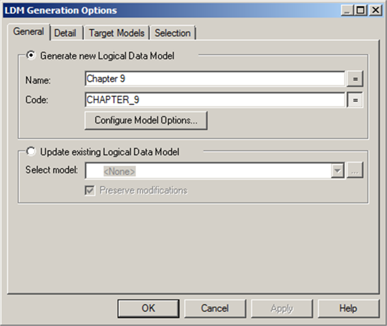
Figure 12.21 - Diagram tabs

Viewing Generation Links
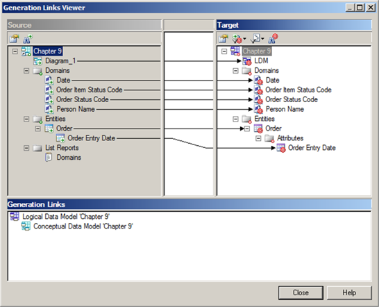
You can see the links between the models via the Generation Links Viewer. On the Tools menu, click on Generation Links; you can then click on either Origin Model or Derived Models, depending on which of the two models is the current one. Either way, you’ll see a window similar to that in Figure 12.22. You’ll need to expand the entries for each model – I’ve done that for you.
In this viewer, you can see a list of every object in both models. In this case, the only object that wasn’t generated to the LDM was the List Report. There are a few other types of objects that also wouldn’t be generated, such as Extensions and Reports. These objects can’t be directly translated from one model type to another. If you had generated another CDM from your CDM, the List Report would have been copied.
If you double-click any of the object names, you can open a read-only property sheet for that object. In small models such as these, it’s easy to see the generation links. In larger models, or models that have generation links to multiple models, you may need to take advantage of the toolbar in the Target pane to filter the items displayed.
![]() “The Generation Links Viewer” (Core Features Guide)
“The Generation Links Viewer” (Core Features Guide)
Figure 12.22 Generation Links Viewer
YOUR TURN TO PLAY
1. Close the viewer, and open the ‘Version’ tab on the property sheet for any object in the LDM; here you can see details of the object from which it was generated, and a tool that allows you to open the property sheet for the original object. Now open the ‘Dependencies’ tab for any entity in the CDM (see Figure 12.23); you’ll see a sub-tab called ‘Generated As’, which provides information about the entity you generated – double-click the entry to open the property sheet for the generated entity. You’ll also see a sub-tab called ‘Diagrams’, which lists the diagrams that display the entity. Again, double-clicking an entry in this list will open the diagram.
2. On the ‘Generated As’ sub-tab, click on ‘Impact and Lineage Analysis’. Figure 12.24 shows part of the result. This is a fairly simple analysis; later in the book we’ll show a more complicated example.
3. Ensure that ‘LDM’ is the current diagram – click on the diagram’s tab if you need to be certain.
4. Create two more entities, called Order Line and Customer.
Figure 12.23 Generation Dependencies

Figure 12.24 Impact and Lineage Analysis

5. Let’s continue working with the same LDM diagram. In the Browser, expand the entry for the ‘Order’ entity until you can see the name of the attribute. Now use the left mouse button to drag the attribute to the Order Line entity, and hold down the <CTRL> key while you release the mouse button. You have copied the attribute to a new entity. If you repeat the exercise, you can create another copy of the attribute, with the name suffixed by ‘2’.
6. Now you’re going to create another copy of the attribute via the diagram. First, center the whole diagram by pressing <F8>. Now zoom until you can see all entities clearly; you can press <F6> to zoom in, and <F7> to zoom out. Alternatively, press <Ctrl>, and scroll with the mouse wheel. You can also use the combination of <Shift> and the mouse wheel to scroll sideways. Click on the Order Entity, then click on the Order Entry Date attribute. Your entity should look like Figure 12.25, with the selected attribute highlighted.
Figure 12.25 Selecting an attribute

7. Now drag the attribute name onto the Customer entity, and drop it into the ‘attribute’ part of the symbol. You have moved the attribute to a new entity.
8. Now drag the attribute back to ‘Order’, this time holding down <Ctrl>, and copy the attribute. Both entities now have an attribute called ‘Order Entry Date’. Repeat this three more times, so you have four attributes in ‘Order’. Notice that you can choose where to drop the attribute in the list – use the line that appears on the target entity to help you locate the new place for the attribute.
9. Drag two or three of the attributes in ‘Order’ to a new position in the same symbol. You can select multiple attributes by pressing <Ctrl> or <Shift> when you click on a series of names; this is standard Windows behavior.
10. After selecting an attribute on an entity symbol, you can open the attribute’s property sheet – just double-click the attribute name after selecting it on the symbol.
11. To edit the name of an attribute in the symbol, select the attribute, pause briefly, then click on the name again. You can also select the attribute and press <F2>. Move up and down the list using <Tab> or the cursor (arrow) keys.
12. Remember that you can ‘undo’ any of these actions.
13. Attributes can also be deleted via the entity symbol. Make sure you still have the CDM open before you do this – in the LDM diagram, select the original Order Entry Date attribute in the entity Order, and press <Delete>. PowerDesigner will ask if you really want to do this – click on the <Impact> button. The Impact and Lineage Analysis window shows the impact of deleting the attribute, but it does not yet show the lineage. In the drop-down ‘Lineage Rule Set’, select ‘Global Lineage Analysis’. The analysis results are re-calculated, as shown in Figure 12.26. Here you can see the links back to the CDM attribute (ringed), the data item (highlighted), and the original domain (ringed).
Figure 12.26 Impact of deletion

Each entry in the analysis is labeled with an action description:
[Delete] | The attribute that you’re proposing to delete, and anything else that would also be deleted |
[Lineage] | objects that precede the attribute you’re proposing to delete, such as the domain it references, the Conceptual attribute it was generated from, and the data item that the Conceptual attribute uses |
[Change] | objects that will be changed if you delete the attribute, in this case the entity |
Double-clicking any of the entries in the analysis results, will open the property sheet for that object.
YOUR TURN TO PLAY
1. Click on ‘Close’ to close the window, and then click on ‘No’, so you don’t delete the attribute. There’s one last thing to try out with attributes on symbols; dragging with the right mouse button. Select any attribute on a symbol, and hold down the right mouse button while dragging the attribute to another entity. When you release the button, the menu shown in Figure 12.27 appears.
2. You have a choice of three actions – to copy, move, or replicate the attribute. Just click on the required action. This also works in the Browser.
Figure 12.27 After dragging with right mouse button

You can drag and drop attributes to copy or move them, or to create a shortcut or a replica:
* between entities in the Browser
* between entity symbols on a diagram
* from the Browser to an entity symbol
* from an entity symbol to the Browser
* from a result list (e.g. from Find Objects) to the Browser
See “Creating Objects in a List of Objects”
Click the ‘Add a Row’ tool to add a new entity at the end of the list. You can also create a new entity by using the arrow keys. When you open a list, the name of the first entity is automatically highlighted for editing. Press the down arrow on your keyboard, and you select the second entry. Keep moving the arrow downwards and eventually you’ll move to empty rows, which automatically become entities.
This works in any column in the list: move down the list of modified dates, and you’ll eventually reach empty rows and start creating entities. If you have too many rows, select the rows you want to get rid of, and press <Delete>.
The new entities will not actually exist until you apply the changes via the <Apply> or <OK> buttons, or by double-clicking one of the new entities to access the property sheet. When you do this, you are asking PowerDesigner to edit an object that does not yet exist, so it will ask you to commit all the changes you have just made, first. That means ALL the changes, not just the entity you double-clicked. See Figure 10.33.
Figure 10.33 Commitment required
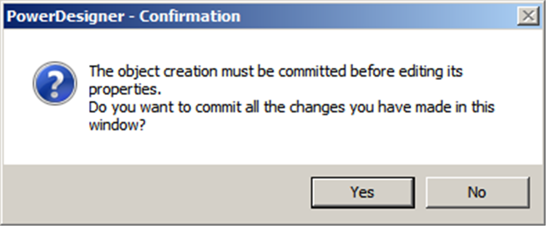
Click <Yes> to carry on, or <No> to go back to the list of objects without applying any changes.
![]() “Object Lists” (Core Features Guide)
“Object Lists” (Core Features Guide)
![]() “Customizing Object List Columns and Filtering Lists” (Core Features Guide)
“Customizing Object List Columns and Filtering Lists” (Core Features Guide)
![]() “Defining a Filter Expression” (Core Features Guide)
“Defining a Filter Expression” (Core Features Guide)
![]() “Customizing Columns in Lists Containing Multiple Types of Objects” (Core Features Guide)
“Customizing Columns in Lists Containing Multiple Types of Objects” (Core Features Guide)
![]() See “Moving, Copying and Deleting Objects” in Chapter 10.
See “Moving, Copying and Deleting Objects” in Chapter 10.
Domain Dependencies
YOUR TURN TO PLAY
- You now have several copies of Order Entry Date, all of which reference the Date domain. In the Browser, open the property sheet for the domain Date, and you’ll see that there are several entries. It should look like Figure 12.29.
- In Figure 12.29, I customized the properties displayed (see Chapter 10), and also sorted the rows by clicking on the column headings; just click on Name or Parent to sort by the values in that column.
As well as dragging attributes between entities, you can also drag them around the ‘Attributes’ tab of the entity’s property sheet.
Open the property sheet for the Order entity, and select the ‘Attributes’ tab. Each entry in the list of attributes has a number; you can select the attribute by clicking on that number. Using the <Ctrl> or <Shift> keys, you can select more than one attribute.
Figure 12.29 Domain Dependencies

You can move the selected attribute(s) to another point in the list in two ways:
* drag them with the mouse
* use the buttons on the re-sequencing toolbar at the foot of the list of attributes, shown in Figure 12.30. The outer buttons move the selection to the top or bottom of the list; the other buttons move them up or down one row at a time.
Figure 12.30 The re-sequencing toolbar

You can drag attributes from the Browser into the list of attributes. You can only copy attributes this way, not move them; nor can you drag them in the opposite direction.
The PowerDesigner Glossary
In environments with a repository, administrators can deploy a glossary of Terms; a Term is a word or phrase that forms part of a controlled vocabulary.
In the ‘Naming Conventions’ section of the Model Options (see Figure 12.31), you can enable the use of the Glossary for auto-completion of names in a model. This will also enable you to check the names of objects for compliance with the terms in the glossary.
Figure 12.31 Enabling the Glossary in a model

If you enable the Glossary in a model, terms are suggested from the Glossary as you type in the name of an object. If you type a recognized synonym for a term, then PowerDesigner suggests that you use the term, instead. The glossary auto-complete feature is limited – it does not work within object and sub-object lists (List of..., ‘Attribute’ tab in Entity properties, etc.).
We don’t assume you have access to a glossary, so we won’t ask you to do anything yourself. Figure 12.32 shows a fragment of a Glossary.
Figure 12.32 Business terms and synonyms
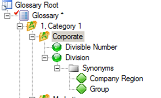
Note the term ‘Division’ and its synonym, ‘Company Region’; also note the term ‘Divisible Number’. In Figure 12.33, I’m part-way through typing in the name of a new data item. After I typed the third letter, PowerDesigner suggested two possible terms that I might wish to use. When I hover the mouse over a term, it displays the term’s ‘comment’ property to help me make my choice.
 The comment is extracted from the repository entry, not from the local Glossary.
All I have to do to comply with the Glossary is to select one of the suggested terms; I can then carry on typing the name, and save it when finished. When I save the new object, it is automatically linked to the term in the Glossary. This linkage can be seen via the Dependencies property of the entity or term, and also via their Impact and Lineage Analysis.
Figure 12.33 PowerDesigner suggested two possible terms

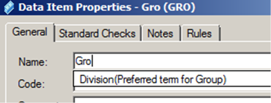
Figure 12.34 shows what happens if I type ‘Gro’ in the name. The word ‘Group’ is a synonym of ‘Division’, so PowerDesigner suggests that I use ‘Division’ instead.
Figure 12.34 Suggesting the preferred term
As well as using the terms in the Glossary to help me decide on object names, I can also use them to validate the names in my model when I run the Model Check. Figure 12.35 shows some of the options available.
Figure 12.35 Checking the model against the Glossary
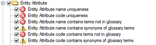
See Chapter 20 to find out more about the Glossary.
Transferring Properties
As you’ve progressed through the previous exercises, you have seen that objects can depend on each other in various ways. Sometimes, the properties of an object are derived from the properties of another object; the property values have been transferred. This happens either by synchronization or by generation.
Synchronization
The property values in a dependent object are the same as those of the equivalent property in another object, which we’ll call the original object. If we change the property value in the original object, the values in the dependent objects also change. Here are some examples that you’ve seen so far:
· Data items and attributes inherit property values from domains
· Conceptual attributes inherit all their properties from data items
· Replica objects inherit all their properties from the original objects, unless changes are made to the replication properties
· The inheritance of attributes by a subtype entity.
Generation
When we generate a new model from an existing model, new objects are generated from existing objects. In some cases, such as domains, the new object is identical to the original object. In other cases, the new object is derived from the original object: for example, a table is derived from an entity.
You can amend the original object and the derived object independently of each other. By default, the links between the original objects and the derived objects are stored when you generate the new model; this allows you to bring them back into line later on. To do that, you run the model generation again, this time updating the model rather than creating a new one.
You will find out more about model generation in Chapter 18.
Managing Allowable Values
PowerDesigner allows you to record lists of values on any data element, so where you record them depends on your strategy for the use of data elements. All data elements have the same ‘Standard Checks’ tab, where you can maintain a list of values – look at Figure 12.36 for a reminder.
Figure 12.36 ‘Standard Checks’ tab
The best type of object to record values is the domain. If you choose to, via the Model Options, you can ensure that all data items, attributes and columns that use the domain automatically inherit changes to the domain values. If a new domain is generated from the original domain by generating a new model, you can ensure that the values are consistent by re-generating the target model(s). If you are unsure of which models you need to re-generate, check the impact analysis for the domain.
The next best place to record values is a data item: this will ensure that the values are the same in conceptual attributes. Re-generating models will ensure that dependent attributes and columns in other models are up to date. Again, check the impact analysis for the data item.
If you prefer not to use domains or data items, identify a single Logical or Physical Data Model as the repository of your lists of values. Whatever approach you take, remember that you can partition any type of data model into packages, and each package can hold a distinct set of data items, entities, or tables, which would allow you to maintain a single model with multiple lists of values for the same thing. Just make sure each package has its own namespace. However, domains are model-level objects – you can only have one domain with a given name in a model.
See “Exporting and Importing Lists of Values”, in Chapter 21.
Dependency Matrices
The Dependency Matrix is a really useful PowerDesigner feature. You can create dependency matrices to review and create links between any two types of objects.
You can create an individual matrix from the Browser, or define a matrix in a model extension for reuse by others. You can also copy them between two models of the same type, but only by merging the models. You cannot use the Windows Clipboard, because PowerDesigner views them as a type of diagram.
For data elements, there are a few essential dependencies that we may be interested in:
· Data items used by entities (via attribute)
· Domains used by data items, attributes, or columns
· Domains (or other objects) and the domains they were generated from.
They are also useful for other objects we have seen so far:
· Entities and the diagrams they appear on
· Terms and the data items they’re used by.
Creating a dependency matrix is a simple operation - right-click a model or package node in the Browser and select New|Dependency Matrix to open the matrix property sheet on the ‘Definition’ tab. To define a matrix, you must:
· Select an object type from the current model to populate your matrix rows and another to populate the matrix columns. Now specify how the rows and columns of your matrix will be associated, by selecting a dependency from the list. You can think of a ‘dependency’ as being a property of the objects in the rows.
· Only direct dependencies are available from the list. You can specify a more complex dependency by clicking the ‘Advanced’ button to open the Dependency Path Definition dialog. We will see an example of this shortly.
· For certain dependencies, the object type on which the dependency is based will be displayed, and you can select an object attribute to display in the matrix cells. You can also select the ‘No value’ symbol, which is displayed if that attribute is not set in any particular instance.
· Click the ‘General’ tab and enter a name for the matrix (for example ‘Domains vs. Data Items’).
· Click OK to complete the definition and open your matrix.
Figure 12.37 shows an example with entity attributes in the rows, and domains in the columns.
Figure 12.37 Domains vs. logical attributes – ‘Definition’ tab
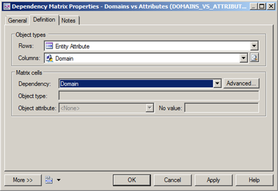
The selected dependency here is the Domain property shown on the property sheet for each logical attribute. If you want to have domains in the rows, the dependency would be ‘Attributes’ – this is the name of the sub-tab on the Domain dependencies tab. Figure 12.38 shows the resulting matrix.
From the matrix, you can access the property sheet of any object listed – just double-click the object name. You can also update the dependency; simply select a cell and press the spacebar or <v>. If the attribute is already linked to a domain, then you will have to select the cell containing ‘P’, and delete the contents. After this, you can link the attribute to another domain.
You cannot update this way in every matrix. Whether or not you can update entries will depend on the types of objects, the connection between them, and the type of property displayed. For example, you cannot update links to terms from the Glossary with a matrix, although you can display them.
Figure 12.38 Domains vs. logical attributes - matrix

The Toolbar allows you to select only empty rows  or populated rows
  , and also to open a selection window
  where you can choose the attributes and domains to be included. The selection window is shown in Figure 12.39.
Figure 12.39 Selecting matrix objects

In this example, the selection list is limited to attributes of the entity ‘Project’.
Whenever you open a matrix, the content is refreshed using the rules in the selection window. In the above example, the content would include any new domains or attributes in the ‘Project’ entity. You can also refresh the content of a matrix while it is open, by clicking on the Refresh tool  , or pressing <F5>. Some new content will appear automatically when you create it, but it is best to be certain that everything you need is included.
The content of the matrix can be exported to an Excel file by clicking on the Export to Excel tool  , or by right-clicking the matrix name in the Browser and selecting Export|Excel.
![]() “Working with Dependency Matrices” (Custom Features Guide)
“Working with Dependency Matrices” (Custom Features Guide)
If your model contains shortcuts to objects in other models, they will appear in the matrix; you will not be able to distinguish them from objects that are not shortcuts. You can de-select them in the selection window shown in Figure 12.38, by simply clicking on the Include External Shortcuts tool ![]() .
.
Advanced Dependencies
You can examine dependencies between two types of objects that are not directly associated with each other by using the Dependency Path Definition dialog, which is accessible by clicking the ‘Advanced’ button shown in Figure 12.36. This allows you to specify a path passing through as many intermediate linking objects as necessary. For example, assume we need to create a matrix showing the link between data items and entities. The objects are not linked directly, they are linked via an intermediate attribute, and so we have to define the path between the objects. Figure 12.40 shows the necessary selections.
Matrices that display advanced dependencies cannot be used to update the model, because the property(s) displayed in the matrix has been derived.
![]() “Specifying Advanced Dependencies” (Custom Features Guide)
“Specifying Advanced Dependencies” (Custom Features Guide)
Figure 12.40 The path from data item to entity

EXERCISE 10: Creating a new Conceptual Data Model in PowerDesigner
Create a new Project in your workspace, called ‘Exercise 10’; make sure the project directory has the same parent directory as the previous projects you created. Find the Excel file that you used to create entities in Exercise 9, and use the Excel Import wizard to create a new Conceptual Data Model from the spreadsheet; call this model ‘Exercise 10’. Rename the diagram to ‘Exercise 10 CDM’. You should now have six entities in the Browser – Color, Ice Cream Cone, Ice Cream Container, Ice Cream Cup, Order, and Order Line. Create the domains shown in Table 12.11. Create some via the Browser, and some via a List of Domains.
Table 12.11 Domains
Domain | Data Type | Length | Precision | List of Values |
Color Code | Characters | 1 |
| b=blue |
Short Name | Characters | 20 |
|
|
Sugar or Wafer Indicator | Characters | 1 |
| S = Sugar |
Height | Number | 3 |
|
|
Ice Cream Container UPC | Number | 16 |
|
|
Standard Identifier | Number | 10 |
|
|
Standard Date | Date |
|
|
|
Standard Large Value | Number | 4 | 2 |
|
Create the data items shown in Table 12.12. Again, try different ways of creating them.