CHAPTER 13
How do I create relationships in PowerDesigner?
PowerDesigner has them
Connecting the dots
In Chapter 5, we identified three levels of relationship, all of which PowerDesigner supports:
Subject Area | Relationships in Conceptual or Logical Data Models |
Logical | Relationships in Logical Data Models |
Physical | References in Physical Data Models |
The fundamentals of relationships are the same for all three levels; all relationships and references are ‘link objects’. Once you have created a link object, it can be modified in the same way as any other object. See Chapter 10 if you need a refresher.
In this chapter, we focus on Relationships in the Conceptual and Logical Data Models. We will see how different References are in the Physical Data Model in Chapter 17.
Rules that you cannot describe using relationships can be defined in PowerDesigner as Business Rules, and linked to any object in any model. If your organization has documented requirements in Microsoft Word documents, you can import those documents into PowerDesigner Requirements models, and link the requirements to any object in any model. See Chapter 23.
Creating Relationships in PowerDesigner
You can create a relationship from the palette, the Browser, or the Model menu.
Creating a Relationship from the Palette
In PowerDesigner, each type of diagram has a specific drawing palette. As you see in Figure 13.1, the palettes for the different types of data models have a lot in common. Nearly all of the tools that you would use to create a relationship or reference show two connected symbols; the only exceptions are the ‘Create Association’ and ‘Create Association Link’ tools on the Conceptual Diagram palette, which are gray, as the selected model notation does not support Merise objects.
Table 13.1 shows the three basic drawing actions and the tools associated with them in each palette.
Figure 13.1 The Diagram palettes


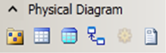
Table 13.1 Relationship drawing actions
| CDM | LDM | PDM |
Create relationship / reference |
|
|
|
Create inheritance (subtype) |
|
|
|
Create many-to-many relationship or new entity with two relationships |
|
|
|


To create a relationship in a Conceptual or Logical Diagram, select the appropriate Relationship tool in the diagram Palette. Decide which direction the relationship needs to go. In Figure 13.2, the modeler wants to draw a new relationship between Entity_7 and Entity_6. There are several ways of visualizing this situation, just use whichever you’re comfortable with:
· Entity_7 is the parent entity, and Entity_6 is the child entity
· Entity_7 is at the one end of the relationship, and Entity_6 is at the many end
· Entity_7 is the parent entity, and Entity_6 is the child entity
· The relationship goes from Entity_7 to Entity_6
Click inside the first entity to link and, while continuing to hold down the mouse button, drag the cursor to the second entity. Release the mouse button inside the second entity, and PowerDesigner will draw the line for you. Drawing an inheritance requires a different technique – see “Subtypes in PowerDesigner” later in this chapter.
Figure 13.2 Drawing a relationship
|
|


The left-hand image in Figure 13.2 shows a relationship being drawn from Entity_7 to Entity_6. When the mouse button is released over Entity_6, the relationship shown in the right-hand image is automatically created.
New relationships are zero-to-many, and completely optional. To revise the optionality and cardinality, open the relationship’s property sheet – see later in this chapter.
 If you make a mistake, and draw the relationship in the wrong direction, all is not lost. Double-click the relationship, and then reverse the entities listed in ‘Entity 1’ and ‘Entity 2’ on the ‘General’ tab of the relationship’s property sheet. See Figure 13.5 for an example.
If you are using ‘free angle corners’ or you haven’t enabled ‘Automatic Link Routing’ in your Display Preferences (see later in this chapter), you can choose the route for the link yourself. Click inside the first entity to link and, while continuing to hold down the mouse button, drag the cursor to the first point at which you want the link to change direction, and release the mouse button. Now click the mouse button wherever you want to create another corner; click on the second entity to complete drawing the line.
 If you have enabled ‘Automatic Link Routing’, PowerDesigner will ignore your suggested route.
Every new relationship is given a default name and cardinalities; it is a fully-optional one-to-many relationship.
When you draw a relationship with the mouse, the positions where you click in the entity symbols become the default positions for the ‘handles’ that form the ends of the relationship. When you lasso symbols to select them, the relationship is only included in the selection if both handles are inside the selection box.
In Chapter 10, we told you about the Disposition options – remember that Arrange Attach Points causes the relationship handles to move to the entity centers, which may result in changes to the routing of the relationship line.
YOUR TURN TO PLAY
1. Open the “Exercises” workspace, and create a new top-level folder called ‘Chapter 13’. Now create a new CDM called ‘Chapter 13’, and save it in your Exercises folder.
2. Access the Display Preferences for the diagram in the new model, and make the following settings:
Show bridges at intersections Enabled
Automatic Link Routing Not Enabled
Relationship Content only include ‘Name’
Relationship Format set corners to the first option (free angles): 
3. Draw four entities on the diagram, with the names and approximate positions illustrated in Figure 13.3. The style and content of the entity symbols doesn’t matter.
Figure 13.3 New diagram - draw these entities

4. Draw a relationship from the middle of entity A to the middle of entity B – don’t attempt to add any corners.
5. Draw a relationship from entity B to entity C – add several corners along the way by clicking on the Canvas (you have to release the mouse button to create the first corner).
Creating a Relationship from a List
Select Model|Relationships to access the list of Relationships, and click the Add a Row tool. If you don’t want to use the default name (see below), type in the name of the relationship. Select the entities via the drop-down lists called ‘Entity 1’ and ‘Entity 2’: if you don’t select two entities, you will not be able to create the relationship. When you click on <Apply> or ‘Create’, the relationship will automatically appear on the diagram.
Remember that you can customize the list of Relationships, so you can display and edit any relationship properties.
YOUR TURN TO PLAY
- Open the list of relationships via the ‘Model’ menu – your two relationships will be shown in the list. Use the Customize Columns and Filter tool to customize the columns displayed in the list to match Figure 13.4.
Figure 13.4 Relationship properties

Table 13.2 lists the properties that you need to include. In some cases, the column heading in the list of relationships is different from the property name, so we’ve highlighted these differences for you.
Table 13.2 Relationship properties to include
Column Heading | Property Name in List |
Name | Name |
Entity 1 | Entity 1 |
(1)->(2) | Entity 1 -> Entity 2 Role Cardinality |
M | Entity 1 -> Entity 2 Role Mandatory* |
(2)->(1) | Entity 2 -> Entity 1 Role Cardinality |
M | Entity 1 -> Entity 2 Role Mandatory |
Entity 2 | Entity 2. |
* this column needs to be moved up the list of properties – select the entry and click the ‘up’ arrow to do this.
2. In the list of relationships, add a new entry to the end of the list, and set Entity 1 to ‘A’, and Entity 2 to ‘C’. Amend the properties of the relationships to match Figure 13.4.
Creating a Relationship in the Browser
This is easy – just right-click the model or package in the Browser, and select New|Relationship. An empty property sheet is opened for the Relationship, showing the ‘General’ tab. You have to choose your two entities before you can create the relationship or switch to a different tab. Remember to click <OK> or <Apply> to save the new relationship.
Relationship Properties
The object properties for relationships look very similar to those of other objects. Figure 13.5 shows the General’ properties tab for a relationship. This is where you provide the name of the relationship, and select the two entities joined by the relationship.
Note the tools to the right of the entity names – working from right to left, these allow you to display the properties of the selected entity, select an entity from a list, and create a new entity. This last option is useful if you need to link the relationship to an entity that doesn’t yet exist – you can create the entity object, amend the relationship, and add the new entity to the current diagram in one single action.
At the top of every tab in the property sheet is a depiction of the relationship using the default style for the diagram; the depiction changes in step with changes you make to the relationship properties. The labels ‘Entity 1’ and ‘Entity 2’ above the entity symbols are actually tools – just click on the label to access the property sheet for the entity.
Figure 13.5 Relationship ‘General’ tab

 PowerDesigner automatically creates relationship names, but you really should change them as soon as you can. The default names, such as Relationship_6, are not very helpful when you are looking at a list of relationships in the Browser, or trying to find a relationship to include on your diagram. Use full names such as “Ice Cream Flavor Dispensed as Scoops”. On the ‘Cardinalities’ tab, you can also provide a role name for each ‘direction’ of the relationship, and you can elect to show all, none, or any of these names for display on a diagram.
Relationship names have to be unique where a pair of entities is connected by two or more relationships. For example, you cannot have two ‘manages’ relationships between the Employee and Department entities.
Relationship names do not have to be unique within a model, but the equivalent ‘codes’ may have to be unique, depending on the model options. By default, the code is automatically generated from the name, so it makes life much easier if you make the names unique. See “Names and Codes in PowerDesigner Objects” in Chapter 10.
![]() “Defining a Code Option for Relationships” (Data Modeling)
“Defining a Code Option for Relationships” (Data Modeling)
The Cardinalities Tab
You have already seen the content of most of the tabs for a relationship, because they are the same as the tabs for other objects. The tab you really need to see now is the ‘Cardinalities’ tab, shown in Figure 13.6. This is the key tab for a relationship, where you specify how the two entities are related.
Figure 13.6 Relationship ‘Cardinalities’ tab
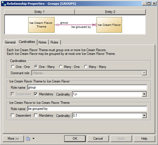
There is a lot of information on the ‘Cardinalities’ tab. The overall cardinalities are set by your choice of one of the four radio buttons at the top. The two drop-down cardinality properties allow you to fine-tune the cardinalities. For example, you could overtype ‘1,n’ in Figure 13.6 with ‘0,4’, which would make the relationship completely optional, and also set the maximum number of Flavors in a Theme to four. Using the Display Preferences, you can display the cardinalities on a diagram. See later in this chapter.
If your relationship cardinalities are ‘One – One’, you can choose the ‘Dominant’ role in the relationship – the primary identifier attributes of the ‘dominant’ entity are migrated along the relationship to the other entity. See “Identifier Migration Along Relationships”, in Chapter 14.
If the child entity is partially identified by the relationship, then you must select the Dependent property.
![]() “Relationship Property Sheet Cardinalities Tab” (Data Modeling)
“Relationship Property Sheet Cardinalities Tab” (Data Modeling)
The Importance of Role Names
In Figure 13.6, the relationship has two role names, one for each direction of the relationship. A role name describes how Ice Cream Flavor Theme is related to Ice Cream Flavor, or vice versa. PowerDesigner uses the role names to generate “assertion statements” for the relationships – see “Assertion Statements” below, for more information.
PowerDesigner will also use the relationship role name to construct the name of attributes migrated via relationships of inheritance links. See “Attribute Migration Settings”, in Chapter 14. When creating a role name, you should use the infinitive phrase that describes the relationship of one entity to the other. For example, each Order may contain one or more lines.
1. In the Browser, create a relationship from entity B to entity D. Set the cardinalities to the entries shown in Figure 13.7.
2. Check the location of the new relationship on the diagram. This is where you realize that, even though you were very careful, you made a mistake. You really meant to add a relationship from C to D, not from B to D. Re-open the property sheet for Relationship_4, and use the drop-down list to change Entity 1 from B to C. The diagram will now look something like Figure 13.8.
Figure 13.7 New relationship via Browser

Figure 13.8 2nd new diagram
