
CHAPTER 18
How can we connect these models in PowerDesigner?
Tie them together
With traceability and
Generation links
The ability to create and manage links between models, and between objects in models, is a key strength of PowerDesigner. There are several types of links, but the key links for data modelers are the generation dependencies created when we generate one model from another. The best way to create models as you move up or down the data model pyramid described in Section IV is to generate each model, in turn. As a reminder, take a look at the model chain illustrated in Figure 18.1, which you may remember from Chapter 9.
Figure 18.1 Generation dependency chain
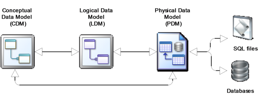
PowerDesigner manages each link in the chain by storing linkage information in all the affected objects. In fact, this is how PowerDesigner manages all such model-to-model and object-to-object links – they refer to it as ‘Link and Sync’. Links are visible on the property sheets for affected objects – generally on one or more of the following tabs:
Dependencies Traceability Links Version Info.
You can see a list of the models your current model is connected to via the list of Target Models on the Model menu. Through the Tools menu, you can start up the Mapping Editor, or view Generation Links.
In addition to generation dependencies, you can create shortcuts to objects, link objects to related diagrams in any model, create replicas of objects and sub-objects, create mappings between models, and create traceability links. You can also create dependency matrices to view or edit links. Project diagrams map out the connections between models.
In addition, there are dedicated methods for linking models, such as mapping data models to data objects in business process models.
Using impact and lineage analysis, you can view the links in the chain, varying the rules to suit your purposes. Via the repository, you can extend the impact analysis beyond the models that you’re aware of, to models you didn’t even know existed in the repository.
Depending on the complexity of your modeling environment, all of these capabilities can give you an administration issue. If you allow every modeler to invent their own strategy for linking models to each other, that will lead to complex and inconsistent model linkages, which will complicate an analysis of the impact of a change. Planning and setting standards is essential.
In this book, we merely scratch the surface of the subject of linking models. In this chapter, we’ll help you to get the best out of the links that we’ve covered.
Generating Models
As you build a pyramid of data models, you will need to create new models and propagate changes through your chain of models. Figure 18.2 illustrates the potential creation and update tasks in a chain of four models. In PowerDesigner, all of these tasks are carried out using model generation. The bold links represent the generation of new models, and the remainder represent the update of one model based on changes made to the other.
Figure 18.2 Model creation and update tasks
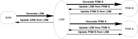
Remember, updates are only applied in one direction. Two-way synchronization requires two updates.
The remainder of this section is a summary of the process you go through when creating or updating a model via the generation feature.
Step 1
Launch the required generation tool via the Tools menu, and choose between creating a new model, or updating an existing one. If there are existing generation dependencies, PowerDesigner will default to the ‘update’ option, as in Figure 18.3, and the drop-down list will include all of the models of that type that were previously generated from the current model. The ellipsis tool (circled in Figure 18.3) opens a list of all the models of that type (see Figure 18.4) in the current workspace, allowing you to choose a previously unlinked model to update. If you want to generate a new model, select the ‘generate’ option in Figure 18.3, and type in a name for the model.
Figure 18.3 Update or create?

Figure 18.4 Select a model

The ‘preserve modifications’ option is vital during an update. If you uncheck this option, PowerDesigner will ignore changes made to previously-generated objects in the target model and overwrite them with the generated version.
Step 2
Look at the remaining tabs (we’ll skip the ‘Target Models’ tab – the documentation will tell you what this is for). The ‘Detail’ tab is shown in Figure 18.5.
Figure 18.5 The ‘Detail’ tab

The ‘Check model’ option will run the standard model checks before generating; any errors will stop the process in its tracks.
The ‘Save generation dependencies’ option will do just what it says – it will create or update generation dependencies to keep a record of how the two models are related.
Figure 18.6 shows the ‘Selection’ tab. By default, all of the objects in the model (where ‘generate’ = True) are selected here, but you can change the selection and save it for future use, if you want to.
Figure 18.6 Your selection
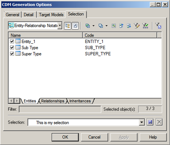
This is a variation on the selection window you’ve seen before – previously, selection windows have only listed one type of object. In Figure 18.6, we have three types of object to choose from, Entities, Relationships, and Inheritances, each with their own tab. We saw the selection window toolbar in Chapter 11. Here we have an additional tool, the Use filter for selection tool  on the right. This tool applies the filter conditions defined in the ‘Customize Columns and Filter’ dialog to select all objects meeting the criteria from the list. This selection by criteria is persistent for as long as the tool is applied.
When you’ve finished here, just click <OK> to continue.
If you see the message shown in Figure 18.7, the model check has found some errors, and the generation process has been halted. The errors are listed in the output window. To carry on with the generation, correct the errors first, or re-run the process with the ‘Check model’ option unchecked.
Figure 18.7 Errors found

Since this is an update process, the next step is to examine the differences between the two models and decide what to do with them. Take a look at Figure 18.8, which has been filtered to show just the things that are different. This is the standard ‘model merge’ dialog, which we will describe in Chapter 23.
Figure 18.8 What shall we change?

![]() “Generating Models and Model Objects” (Core Features Guide)
“Generating Models and Model Objects” (Core Features Guide)
Generating Model Objects
You can extend the inter-model generation capabilities provided by PowerDesigner by defining your own object generation commands. You can define as many commands as you want, and generate any of your model's objects as any kind of objects in any other model. The generated objects are linked to the original objects and can be resynchronized at any time.
This feature is available by selecting Generate Objects on the Tools menu. It’s useful for ad-hoc generation of objects, but you should make sure there isn’t another way of achieving the same objective before you use it.
![]() “Generating Model Objects” (Core Features Guide)
“Generating Model Objects” (Core Features Guide)
Traceability Links
You can use traceability links to show any kind of relationship between two model objects (including between objects in different models)
Traceability links are under your control. You can add them in an object’s property sheet (via the ‘Traceability Links’ tab), draw them on a diagram (using the Link/Traceability Link tool  ), or create them via a dependency matrix. You can categorize links by creating your own link types.
For example, let’s suppose that we decide to add traceability links from a Dimensional model back to the original Relational model. Rather than using an unclassified link, we will create a new type of link specifically for this task.
To create the new Link Type, open the property sheet for an attribute; on the ‘Traceability Links’ tab, click the Types and Grouping tool, and then select ‘New Link Type’. Type in ‘Relational Source’ and click <OK>.
The new Link Type will be created within a new model extension called Local Extensions, which you can see in the Browser.
Staying in the ‘Traceability Links’ tab, click on the ‘Types and Grouping’ tool and select ‘Group By Link Type’. A new sub-tab will appear, called ‘Relational Source’. Now click on the ‘Add Objects’ tool  , and the ‘Add Objects’ window will appear. In the ‘Model’ selection box, select the model you want to link to, and then select an object or sub-object. Click on <OK> twice.
Congratulations, you have created a traceability link, and also created a model extension.
Figure 18.9 shows such a link, and the view of the same link from the Relational attribute, shown in the ‘Dependencies’ tab.
Figure 18.9 A traceability link
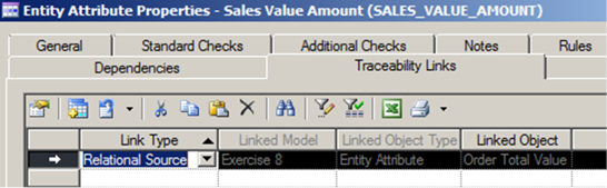
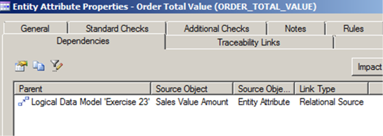
The list of columns has been customized in both of these property sheets, to include information that helps us understand the link. Refer back to “Object Lists” in Chapter 10. The Link Type property was included, to provide a drop-down list in the ‘Traceability’ tab. If you double-click an entry in either list, you will open the property window for the linked object.
Traceability Links have direction – each link has an outgoing connection and an incoming connection, illustrated in Figure 18.10.
Figure 18.10 Incoming and outgoing traceability links

You will need to understand this distinction when creating reports or dependency matrices that contain traceability links. The link can be viewed from both ends, but it can only be created, edited or deleted in the object that has the outgoing connection, such as Sales Value Amount in the example above. You will need to bear this in mind when working out how best to manage traceability – you can’t expect an analyst to create an outgoing connection in a model they can’t update.
![]() “Creating Traceability Links” (Core Features Guide)
“Creating Traceability Links” (Core Features Guide)
The Mapping Editor
In PowerDesigner, mappings are designed to document the transfer of data between the database represented by two PDMs. In reality, they can be used to link any two data models to each other. Mappings between PDMs can be transformed into a data movement model.
The Mapping Editor is available on the Tools menu. You need to supply a name for the mapping, and choose a model to map from – this model will be treated as the source model in the mapping. You can create mappings via the ‘Mapping’ tab on an object, if you prefer, but the Mapping Editor gives you a visual display of the mappings. It also allows you to create a set of default mappings simply by finding objects in the two models that have the same name, and then linking them to each other. A sample Mapping Editor view is shown in Figure 18.11.
Figure 18.11 Sample Mapping Editor window

![]() “Linking and Synchronizing Models” (Core Features Guide)
“Linking and Synchronizing Models” (Core Features Guide)
![]() “Object Mappings (Core Features Guide)
“Object Mappings (Core Features Guide)
Key Points · Linking models and objects to each other is a key strength of PowerDesigner. · Generation dependencies are key for data modelers. · Model generation also includes model updates. · Don’t forget to preserve modifications during an update. · Save the generation dependencies. · Traceability links are under your control. · Mappings can be complex things. |