
This chapter covers the following testing objectives for Novell Course 3004: Novell Network Management and Novell Course 575: Novell eDirectory Design and Implementation:
![]() Identify NetWare 6 TCP/IP Components (3004)
Identify NetWare 6 TCP/IP Components (3004)
![]() Migrate from IPX to IP (3004)
Migrate from IPX to IP (3004)
![]() Identify How DNS Services Work (3004)
Identify How DNS Services Work (3004)
![]() Identify How DHCP Services Work (3004)
Identify How DHCP Services Work (3004)
![]() Design and Implement an eDirectory DNS/DHCP Strategy (575)
Design and Implement an eDirectory DNS/DHCP Strategy (575)
![]() Configure DNS Services (3004)
Configure DNS Services (3004)
![]() Configure DHCP Services (3004)
Configure DHCP Services (3004)
![]() Configure Dynamic DNS Services (3004)
Configure Dynamic DNS Services (3004)
![]() Create a Private Network Using NAT (3004)
Create a Private Network Using NAT (3004)
![]() Design and Implement an SLP Strategy (575)
Design and Implement an SLP Strategy (575)
![]() Configure SLP (3004)
Configure SLP (3004)
Now that you’ve constructed the NetWare 6 server and client, it’s time to pour the electronic pavement of our information superhighway—also known as TCP/IP. TCP/IP is the Internet’s main protocol suite. It consists primarily of the Internet Protocol (IP), which provides network layer routing, and the Transmission Control Protocol (TCP), which operates at the transport layer. Today TCP/IP is the de facto industry protocol standard for global communications.
In years past, NetWare supported only native NetWare Core Protocol (NCP) requests over the Internetwork Packet Exchange (IPX) protocol. This protocol requires little administrative intervention to configure and maintain. Novell has now added native NCP support for TCP/IP, thus eliminating the need to encapsulate.
To effectively build and manage a TCP/IP network, you must become an expert in all the critical TCP/IP administrative features included with NetWare 6. Fortunately, that’s the goal of this chapter. In the following one hundred pages or so, we’ll study the following TCP/IP components in great detail:
![]() IP—All NetWare 6 core protocols can use the benefits of TCP/IP’s open connectivity. This provides the capability to run in a pure IP environment—pure in the sense that NetWare 6 can be configured to offer NCP services natively over the TCP/IP stack, eliminating the need for IPX-based encapsulation (or, in the case of NT Server, NetBIOS encapsulation). In other words, a NetWare 6 server configured for IP-Only uses TCP/IP rather than IPX/SPX as the transport mechanism for all NCP calls. This eliminates the need for multiple protocols on the wire and frees valuable network bandwidth. Of course, IP doesn’t come without its fair share of management costs. Fortunately, NetWare 6 offers some relief in the form of Compatibility Mode and Novell DNS/DHCP Services.
IP—All NetWare 6 core protocols can use the benefits of TCP/IP’s open connectivity. This provides the capability to run in a pure IP environment—pure in the sense that NetWare 6 can be configured to offer NCP services natively over the TCP/IP stack, eliminating the need for IPX-based encapsulation (or, in the case of NT Server, NetBIOS encapsulation). In other words, a NetWare 6 server configured for IP-Only uses TCP/IP rather than IPX/SPX as the transport mechanism for all NCP calls. This eliminates the need for multiple protocols on the wire and frees valuable network bandwidth. Of course, IP doesn’t come without its fair share of management costs. Fortunately, NetWare 6 offers some relief in the form of Compatibility Mode and Novell DNS/DHCP Services.
![]() Compatibility Mode—NetWare 6 also includes significant backward compatibility with older IPX-based networks via its Compatibility Mode. With Compatibility Mode enabled, you can execute IPX-based applications on special IP-based Compatibility Mode network segments and ensure compatibility between IP and IPX networks.
Compatibility Mode—NetWare 6 also includes significant backward compatibility with older IPX-based networks via its Compatibility Mode. With Compatibility Mode enabled, you can execute IPX-based applications on special IP-based Compatibility Mode network segments and ensure compatibility between IP and IPX networks.
![]() Novell DNS/DHCP Services—To help ease the IP management burden, NetWare 6 includes two TCP/IP administration services for IP address allocation and host configuration. First, Domain Name System (DNS) offers a distributed name/address database to translate numerical IP addresses into alphanumeric names. You configure DNS as a service to run on a NetWare server by using the command NAMED.NLM, which can be added to the AUTOEXEC.NCF file so that it launches each time the server is started. Second, the Dynamic Host Configuration Protocol (DHCP) provides a framework for dynamically passing configuration information to TCP/IP clients. To launch the service, you use the command DHCPSRVR.NLM, which can also be added to the AUTOEXEC.NCF file so that it launches each time the server is started. The server running DHCPSRVR.NLM dynamically assigns available IP addresses to clients in response to their requests. This server is called (no surprise here) the DHCP server.
Novell DNS/DHCP Services—To help ease the IP management burden, NetWare 6 includes two TCP/IP administration services for IP address allocation and host configuration. First, Domain Name System (DNS) offers a distributed name/address database to translate numerical IP addresses into alphanumeric names. You configure DNS as a service to run on a NetWare server by using the command NAMED.NLM, which can be added to the AUTOEXEC.NCF file so that it launches each time the server is started. Second, the Dynamic Host Configuration Protocol (DHCP) provides a framework for dynamically passing configuration information to TCP/IP clients. To launch the service, you use the command DHCPSRVR.NLM, which can also be added to the AUTOEXEC.NCF file so that it launches each time the server is started. The server running DHCPSRVR.NLM dynamically assigns available IP addresses to clients in response to their requests. This server is called (no surprise here) the DHCP server.
TIP
Dynamic DNS (DDNS) enables the hostname-to-IP address table (sometimes called the DNS database) to be instantly notified and updated with address assignments made by DHCP servers. A DNS database is a snapshot of the current hostnames and IP addresses, which means it is static. After the snapshot has been taken, you can configure DDNS to update the database dynamically each time DHCP makes a new IP address assignment. This is very cool stuff!!
![]() Network Address Translation (NAT)—Where registered IP addresses are required to connect to the Internet or public network, NAT enables networks that use nonregistered IP addresses on a private network to connect by translating between them and public addresses. NAT also serves as a partial firewall by keeping individual IP addresses hidden from the outside world, which provides some added security at the network layer of the OSI model.
Network Address Translation (NAT)—Where registered IP addresses are required to connect to the Internet or public network, NAT enables networks that use nonregistered IP addresses on a private network to connect by translating between them and public addresses. NAT also serves as a partial firewall by keeping individual IP addresses hidden from the outside world, which provides some added security at the network layer of the OSI model.
![]() Service Location Protocol (SLP)—In the past, NetWare used the Service Advertising Protocol (SAP) method of identifying and discovering network services. In NetWare 6, you have three main choices: Service Location Protocol (SLP), Dynamic Host Configuration Protocol (DHCP), and static configuration. In addition to these, eDirectory and DNS offer service location capabilities. The first (and most popular) service-discovery method is SLP. This IP migration component provides automatic resource discovery and registration on a TCP/IP network. SLP is particularly advantageous because it provides full backward compatibility with IPX-based network services and with applications that rely on SAP discovery. By registering information about the location of network services in a database, SLP allows clients to query the database to find those services. SLP is an Internet standard protocol (RFC 2165).
Service Location Protocol (SLP)—In the past, NetWare used the Service Advertising Protocol (SAP) method of identifying and discovering network services. In NetWare 6, you have three main choices: Service Location Protocol (SLP), Dynamic Host Configuration Protocol (DHCP), and static configuration. In addition to these, eDirectory and DNS offer service location capabilities. The first (and most popular) service-discovery method is SLP. This IP migration component provides automatic resource discovery and registration on a TCP/IP network. SLP is particularly advantageous because it provides full backward compatibility with IPX-based network services and with applications that rely on SAP discovery. By registering information about the location of network services in a database, SLP allows clients to query the database to find those services. SLP is an Internet standard protocol (RFC 2165).
Now, I think we’re ready to take a detailed look at the challenge of migrating to IP. What do you think?
Let’s migrate...
Test Objective Covered:
![]() Identify NetWare 6 TCP/IP Components (3004)
Identify NetWare 6 TCP/IP Components (3004)
![]() Migrate from IPX to IP (3004)
Migrate from IPX to IP (3004)
As you just learned, NetWare 6 enables you to access NetWare services through the use of pure IP. Although many network administrators might use both TCP/IP and IPX on their current networks, an IP-Only system is more easily integrated with other operating systems, such as Unix and Windows NT/2000/XP.
Because of the complexity of migrating an IPX-based network to an IP-based network, the migration components have been integrated into NetWare 6 instead of being placed in a separate migration tool. These migration components are used by the server only when required. Because an IPX stack is loaded on the server, some IPX symbols might persist. This does not mean, though, that the system is using IPX on the wire—only that the system is compatible with IPX if it needs to be.
The good news is that the challenges of migrating to IP-Only are more than offset by the benefits of a single protocol network. In short, an IP-Only network increases the throughput on taxed network segments and improves overall interoperability. In this overview section, we’ll begin with three different protocol configurations: IP-Only, IPX-Only, and IP and IPX together. Then we’ll discover some exciting IP migration scenarios, and offer some simple steps for configuring Compatibility Mode servers/clients. Next, we’ll learn how to expand IP addresses within private and public networks using Network Address Translation (NAT). Finally, we’ll explore service discovery and SAP redirection using the Service Location Protocol (SLP).
NetWare 6 uses the following modules to implement TCP/IP:
![]() BSDSOCK.NLM—Provides Berkeley Software Distribution (BSD) standards sockets interface
BSDSOCK.NLM—Provides Berkeley Software Distribution (BSD) standards sockets interface
![]() TCP.NLM—Provides the transport layer TCP and User Datagram Protocol (UDP) interfaces
TCP.NLM—Provides the transport layer TCP and User Datagram Protocol (UDP) interfaces
![]() TCPIP.NLM—Provides IP, Internet Control Message Protocol (ICMP), Internet Group Management Protocol (IGMP), routing, and other network layer protocols
TCPIP.NLM—Provides IP, Internet Control Message Protocol (ICMP), Internet Group Management Protocol (IGMP), routing, and other network layer protocols
![]() TCPCFG.NLM—Provides TCP/IP configuration
TCPCFG.NLM—Provides TCP/IP configuration
![]() NETLIB.NLM—Provides libraries for TCP/IP modules
NETLIB.NLM—Provides libraries for TCP/IP modules
![]() INETCFG.NLM—A utility that initializes TCP/IP on the server, usually in conjunction with TCPCFG.NLM
INETCFG.NLM—A utility that initializes TCP/IP on the server, usually in conjunction with TCPCFG.NLM
Now let’s take a look at the three different protocol configurations offered by NetWare 6. Then we can use this information to explore a variety of IP migration scenarios.
Your ability to support IP-Only and/or IPX-Only connectivity within your WAN relies entirely on how the clients and servers are configured during installation. In NetWare 6, you have three different protocol configuration options:

The protocol configuration you choose determines the binding between protocol stacks and network adapters.
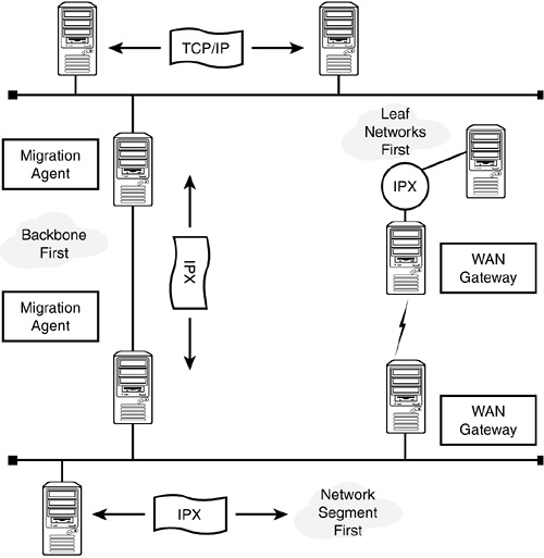
As mentioned, Figure 6.1 has three network configurations (IP, IPX, and Compatibility Mode) servicing four server configurations (IP-Only, IPX-Only, Dual Stack, and Compatibility Mode).
Now let’s take a closer look at each of these protocol configurations because you’ll probably come across each of them during your migration from an IPX to an IP network.
If you install your NetWare 6 clients and servers using the IP-Only install option, you’ll end up with a Pure IP network (refer to Figure 6.1). Therefore, IP-Only servers load only the TCP/IP protocol stack, and bind it to the internal network adapter. The IPX protocol stack is loaded on IP systems to give them the capability to execute IPX applications and to connect to IPX LANs through a migration agent.
If you install your NetWare 6 clients and servers using the IPX-Only install option, you’ll end up with a pure IPX network (refer to Figure 6.1). Servers installed using the IPX-Only option load only the IPX stack, and binds it to the internal network adapter.
If you configure your NetWare 6 servers and clients for IP and IPX, you’ll end up with a mixed network (refer to Figure 6.1).This third protocol configuration option can be accomplished at the NetWare 6 client/server in one of two ways:
![]() Dual stacks—The server and client are configured with both protocol stacks (refer to Server B in Figure 6.1). This means each machine supports both the IP and IPX protocols. Although this creates overhead on the network wire, it ensures multiprotocol connectivity.
Dual stacks—The server and client are configured with both protocol stacks (refer to Server B in Figure 6.1). This means each machine supports both the IP and IPX protocols. Although this creates overhead on the network wire, it ensures multiprotocol connectivity.
![]() Compatibility Mode—This second option occurs automatically if you select the IP-Only option when you install a NetWare 5 server. In this case, the IPX Compatibility Mode Driver (CMD) creates a virtual IPX network within the IP-Only WAN (refer to Server E in Figure 6.1). This is the preferred option because it doesn’t cause any network bandwidth overhead. As you’ll learn in just a moment, a CMD Network requires a migration agent for connection to IPX-Only networks (refer to Server D in Figure 6.1).
Compatibility Mode—This second option occurs automatically if you select the IP-Only option when you install a NetWare 5 server. In this case, the IPX Compatibility Mode Driver (CMD) creates a virtual IPX network within the IP-Only WAN (refer to Server E in Figure 6.1). This is the preferred option because it doesn’t cause any network bandwidth overhead. As you’ll learn in just a moment, a CMD Network requires a migration agent for connection to IPX-Only networks (refer to Server D in Figure 6.1).
This completes our brief discussion of NetWare 6 client/server protocol configurations. As you can see, the choices you make during installation dramatically affect your ability to communicate in a mixed IP and IPX environment. Choose wisely. Now let’s continue our discussion of IP migration with a detailed look at some interesting migration scenarios.
The strategy that you choose to migrate your existing network to IP-Only depends on a number of important criteria, such as the migration path that you’re using (IPX to IP, for example), the size of your network, your company’s Internet access requirements, and your users’ IPX compatibility needs.
Some small networks (with minimal legacy considerations) might consider an immediate rollover to the IP protocol. This is possible with a little planning and a good understanding of how to build an IP infrastructure. However, most large installations will require some time for the transition to an IP-Only network. NetWare 6 provides the tools that you can use to first clear the wire (that is, create IP-Only network traffic) and then clean the applications (replacing legacy IPX applications with versions that support IP).
The gradual phased transition from IPX to IP is made possible because of NetWare 6’s Compatibility Mode and migration agent features. In this section, we explore three basic approaches to a phased migration to IP (see Figure 6.2):
![]() Network segments first—This approach focuses on the migration and the immediate rollover of a specific segment of your network to IP-Only. After that segment has resolved any application-support problems, the next segment is attacked. This way you can gradually roll over your network one piece (segment) at a time.
Network segments first—This approach focuses on the migration and the immediate rollover of a specific segment of your network to IP-Only. After that segment has resolved any application-support problems, the next segment is attacked. This way you can gradually roll over your network one piece (segment) at a time.
![]() Leaf networks first—This approach is similar to the previous approach; however, it focuses on distributed WAN networks instead of segments. These leaf networks can be immediately rolled over to IP-Only and eventually connected to the WAN backbone using IPX/IP migration agents.
Leaf networks first—This approach is similar to the previous approach; however, it focuses on distributed WAN networks instead of segments. These leaf networks can be immediately rolled over to IP-Only and eventually connected to the WAN backbone using IPX/IP migration agents.
![]() Backbone first—Finally, you might consider replacing IPX on the network backbone with IP-Only first. This approach focuses on the cost savings that can be realized by a routing infrastructure that supports only one protocol. By allowing IPX and IP compatibility on leaf networks, you can minimize risk and disruption to overall operations.
Backbone first—Finally, you might consider replacing IPX on the network backbone with IP-Only first. This approach focuses on the cost savings that can be realized by a routing infrastructure that supports only one protocol. By allowing IPX and IP compatibility on leaf networks, you can minimize risk and disruption to overall operations.
Let’s take a closer look at each of these three IP migration scenarios.
The first option for a phased IP migration is to identify specific segments of the WAN and roll them over first (see Figure 6.2). For this scenario to work successfully, the network segment that you choose must not be used to interconnect any other sections of the network using IPX. The following five steps should be followed:
1. Select and upgrade/install a specific number of servers in the network segment to act as migration agents. We’ll discuss migration agents in just a moment.
2. Upgrade/install all servers in the network segment using the IP and IPX option.
3. Upgrade/install all clients in the network segment using the IP-Only option.
4. Modify the configuration of the servers and services in the network segment so that they resolve requests using IP-Only. Unbinding IPX from all server adapters and loading the SCMD.NLM without /MA can accomplish this.
5. Turn off IPX networking between the selected segment and the rest of your WAN.
By following these steps, you can upgrade or install IP servers/clients in a phased manner without losing connectivity.
Migrating leaf networks first reduces the impact of the migration on the IPX routing infrastructure. It also enables you to focus efforts on specific geographically separated sites (see Figure 6.2). Keep in mind, however, that because the backbone is the last portion of the network that migrates, administrative costs might not be reduced as quickly as with other methods.
The following are the steps necessary to migrate a network from IPX to IP starting with the leaf networks:
1. Identify the nodes and links that form the backbone of the network.
2. Select and upgrade/install specific servers in the backbone to act as migration agents.
3. Select the leaf portion of the network that will be migrated. This could be, for instance, a group of segments connected to the backbone via a WAN link. Then migrate the selected segment of the network following the steps outlined previously in the section, “Migrating a Network Segment First.”
4. Repeat step 3 until all networks connected to the backbone have been migrated.
5. Migrate the network backbone to IP-Only using the tasks described in step 3.
Migrating the network backbone first alleviates administrative costs associated with supporting multiple protocols over the backbone. This migration path requires a migration agent (with the Backbone Support feature enabled) on each segments that’s connected to the backbone. After both of these features have been installed, you can disable IPX routing on the backbone (refer to Figure 6.2).
The following steps describe the process of migrating a network from IPX to IP, starting with the backbone:
1. Identify the nodes and links that form the backbone of your network.
2. Select and upgrade/install specific servers in each of the distributed network segments as migration agents. Be sure to use the Backbone Support option when you install the migration agents.
3. Migrate the network backbone using the steps outlined previously in the “Migrating a Network Segment First” section.
4. Identify the leaf portions of the network that you would like to migrate when the backbone is routing IP-Only. Migrate each leaf network one-by-one using the steps previously outlined in the “Migrating Network Segments First” section.
5. Repeat step 4 until all networks connected to the backbone are migrated and you’re living in an IP world.
This completes our discussion of IP migration in NetWare 6. As you can see, there’s much more to pure IP than meets the eye. So far, we’ve discovered three different protocol configurations and explored some sample migration scenarios. The centerpiece of IP migration is a well-configured Compatibility Mode server. So, now’s an excellent time to explore NetWare 6’s IPX Compatibility Mode configuration.
As you just learned, it’s crucial to maintain IP and IPX compatibility during migration to IP. Novell created the Compatibility Mode feature to facilitate migration to IP and maintain backward compatibility for IPX-based applications. This technology provides on-demand support for existing IPX applications, while maintaining full support for IP-based and NCP-based applications. Some IPX-dependent applications make legitimate NCP calls, whereas others use what are commonly called dirty hooks, or the practice of directly accessing the IPX stack itself without using NCP calls. Compatibility Mode also provides backbone support, which in turn facilitates connecting two disconnected IPX networks across an IP-Only backbone.
Compatibility Mode technology consists of two components working together: Compatibility Mode Server (the CMD NLM running on the server as SCMD.NLM) and Compatibility Mode Client (the CMD service running on the client). Furthermore, the CMD NLM can be run in one of three modes: CMD (providing backward compatibility for legacy IPX applications), Migration Agent (enabling IP and IPX segments or networks to be connected), and Backbone Support (enabling IPX segments to connect over an IP backbone).
In this section, we’ll discuss the following Compatibility Mode topics in greater depth:
![]() Compatibility Mode server—The Compatibility Mode server is configured in such a way that all basic OS applications behave both as IP-Only applications and as IPX-Only applications (and advertise themselves accordingly). For example, the Compatibility Mode server (Node E in Figure 6.1) enables eDirectory synchronization between an IP-Only server (Node A) and an IPX-based server (Node C) via the migration agent. Similarly, if Network Print Services behave as IPX-based queues in an IP environment, an IPX client can use the queues by accessing the Compatibility Mode driver.
Compatibility Mode server—The Compatibility Mode server is configured in such a way that all basic OS applications behave both as IP-Only applications and as IPX-Only applications (and advertise themselves accordingly). For example, the Compatibility Mode server (Node E in Figure 6.1) enables eDirectory synchronization between an IP-Only server (Node A) and an IPX-based server (Node C) via the migration agent. Similarly, if Network Print Services behave as IPX-based queues in an IP environment, an IPX client can use the queues by accessing the Compatibility Mode driver.
![]() Compatibility Mode client—A Compatibility Mode IP-Only client can access the services being provided by a Compatibility Mode server and can also access the services being provided by an IPX-Only server through the migration agent component. The CMD client runs on a Windows workstation.
Compatibility Mode client—A Compatibility Mode IP-Only client can access the services being provided by a Compatibility Mode server and can also access the services being provided by an IPX-Only server through the migration agent component. The CMD client runs on a Windows workstation.
![]() Migration agent—The migration agent resides on a CMD server and acts as a gateway between the existing network and the IP-Only network. Figure 6.1 shows a Compatibility Mode gateway (Server D) connecting two dissimilar networks: a CMD network and an IPX network. This node should be accessible to all clients/servers from both networks. In short, the migration agent provides IPX-based services to IP segments and IP-based services to IPX segments. In addition, the migration agent provides service visibility and accessibility between IPX networks that are connected through an IP-Only backbone—using the MA (Migration Agent) tag.
Migration agent—The migration agent resides on a CMD server and acts as a gateway between the existing network and the IP-Only network. Figure 6.1 shows a Compatibility Mode gateway (Server D) connecting two dissimilar networks: a CMD network and an IPX network. This node should be accessible to all clients/servers from both networks. In short, the migration agent provides IPX-based services to IP segments and IP-based services to IPX segments. In addition, the migration agent provides service visibility and accessibility between IPX networks that are connected through an IP-Only backbone—using the MA (Migration Agent) tag.
Now let’s take a closer look at how we configure Compatibility Mode servers, clients, and migration agents.
The Compatibility Mode server and migration agent capabilities are integrated into a single module called SCMD.NLM. This module is called the Compatibility Mode Driver (CMD), and it’s bundled with NetWare 6.
The CMD provides IPX protocol support on an IP-Only network by doing the following:
![]() Directs normal NCP communication through IP
Directs normal NCP communication through IP
![]() Redirects outbound SAP packets to SLP, which registers the IPX-based service with the local service agent (SA)
Redirects outbound SAP packets to SLP, which registers the IPX-based service with the local service agent (SA)
![]() If necessary, it translates the inbound SLP traffic related to the IPX service to SAP
If necessary, it translates the inbound SLP traffic related to the IPX service to SAP
![]() Encapsulates outgoing IPX packets in UDP or TCP and sends them to the IP stack
Encapsulates outgoing IPX packets in UDP or TCP and sends them to the IP stack
![]() Decapsulates (if that’s a word) incoming packets containing encapsulated IPX information and redirects them to the IPX stack
Decapsulates (if that’s a word) incoming packets containing encapsulated IPX information and redirects them to the IPX stack
The functionality of SCMD.NLM depends on the options you use when the module is loaded:
![]() Compatibility Mode server—LOAD SCMD
Compatibility Mode server—LOAD SCMD
![]() Migration agent—LOAD SCMD /MA
Migration agent—LOAD SCMD /MA
![]() Migration agent with backbone support—LOAD SCMD /MA
Migration agent with backbone support—LOAD SCMD /MA
The Compatibility Mode driver is the centerpiece of IP migration. Fortunately, it’s loaded automatically in NetWare 5 when the IP-Only option is used. You have to load it manually in NetWare 6. Another key point is the presence or absence of IPX in the Compatibility Mode server. You must bind IPX to all server NICs if the CMD server is acting as a migration agent or offering backbone support. On the other hand, you cannot bind IPX to any server NICs if the CMD server is operating in standard Compatibility Mode.
TIP
Consider placing the SCMD load command in your AUTOEXEC.NCF file so that it launches each time the server is started. Place the command after the LOAD and BIND statements for the LAN drivers or after the INITSYS.NCF.
The Compatibility Mode driver treats the IP network as a virtual IPX network segment—called a CMD network segment (see Figure 6.1). The default virtual IPX network number used by CMD is FFFFFFFD. You can configure an IPX network other than this by using the following command:
LOAD SCMD /NET=IPX_network_number
As I’m sure you’ve guessed, SLP must be enabled across the network for IPX applications to work on IP networks. Additionally, at least one migration agent (shown in Figure 6.1) must be used on the network if you interconnect IPX and IP segments.
The good news is that the services of the CMD drivers are utilized only when the system needs to process an IPX-based application. Also, these drivers kick in automatically when an IP-Only client tries to establish a connection with an IPX-based resource (such as a printer or bindery-based server). When not in use, the IPX compatibility drivers are dormant and do not use network communication bandwidth.
In this section, you learned that CMD servers enable IPX connectivity in an IP-Only WAN by creating a virtual IPX network segment. However, if you need to communicate with a real IPX network, you should configure your CMD server as a migration agent. Before we examine that, let’s take a closer look at configuring the CMD client.
You can add the CMD client by selecting IP with IPX Compatibility during the Protocol Preference stage of your Novell Client installation. After you’ve specified that the workstation should use CMD, it expects to receive CMD parameters from a DHCP server. You can also configure your Subnet object to deliver CMD configuration parameters to the workstations. We’ll discuss DNS/DHCP objects in detail later in the chapter, but for now be aware that you follow these steps to deliver CMD configuration parameters to the workstations (provided that the DHCP Server has been loaded):
1. From iManager, expand DHCP Management and select Global DHCP Configuration.
2. Select Set Global Preferences and then click OK.
3. Select Modify. Add 63-12 IPX Network Number.
4. Enter the appropriate IPX network number of the CMD virtual network. The default is FFFFFFFD. This option delivers the IPX network number of the CMD virtual number, so it must match the number used on the server.
5. Save your changes and unload and reload DHCPSRVR.NLM.
If you prefer, you could instead manually configure IPX compatibility parameters on the Novell Client Windows workstation by following these steps:
1. Right-click My Network Places and select Properties.
2. Right-click Local Area Connection and select Properties
3. Select Novell Compatibility Mode Driver and then select Properties.
When the Properties window appears, you can configure the following parameters:
![]() Use DHCP—This option configures the client to receive its CMD configuration parameters from a DHCP server. If this option is not checked, the CMD client receives configuration parameters from SLP or from statically entered information in the fields that follow.
Use DHCP—This option configures the client to receive its CMD configuration parameters from a DHCP server. If this option is not checked, the CMD client receives configuration parameters from SLP or from statically entered information in the fields that follow.
![]() IPX Compatibility Scope—This option indicates the name of your scope. The CMD driver converts IPX-based SAP information into SLP information and vice versa. Therefore, if an SLP directory agent (DA) is used, its scope object in eDirectory contains information about SAP services.
IPX Compatibility Scope—This option indicates the name of your scope. The CMD driver converts IPX-based SAP information into SLP information and vice versa. Therefore, if an SLP directory agent (DA) is used, its scope object in eDirectory contains information about SAP services.
![]() Network Number—Entered in hexadecimal notation, this option configures the workstation to use a virtual IPX network number other than the default FFFFFFFD. Keep in mind that this number must match the number configured on the CMD server.
Network Number—Entered in hexadecimal notation, this option configures the workstation to use a virtual IPX network number other than the default FFFFFFFD. Keep in mind that this number must match the number configured on the CMD server.
Now I think we’re ready to learn how to configure the CMD server as a migration agent. Let’s take a closer look.
Migration agents are Compatibility Mode servers that act as gateways between IP-Only segments and IPX segments. As you learned previously, a CMD server can become a migration agent simply by loading the SCMD module with the following switch (see Figure 6.1):
LOAD SCMD /MA
This option enables the migration agent capabilities of your Compatibility Mode server. But that’s not all. In addition to the /MA option, you’ll need to make sure that both IP and IPX are bound to the internal server NIC during installation (refer to Chapter 1, “NetWare 6 Installation,” for more information).
After you’ve activated the migration agent, you can test it by typing DISPLAY SERVERS on both your IP and IPX servers. On the IP servers, you should see a list of IPX-based services. Similarly, on your IPX servers, you should see a list of available CMD servers.
You can configure your CMD Client on a Windows workstation to use MAs either dynamically through DHCP or statically:
![]() Dynamically using DHCP—In addition to the DHCP option 63-12: IPX Number in iManager discussed previously in our look at CMD client configuration, two other options affect the way CMD clients work with MAs. The 63-13: IPX Stale Time option specifies a minimum time in minutes that must pass before the client attempts to renew its MA address information. The 63-14: migration agents option specifies a list of IP addresses for NetWare servers hosting MAs. You cannot use option 63-13 and 63-14 together.
Dynamically using DHCP—In addition to the DHCP option 63-12: IPX Number in iManager discussed previously in our look at CMD client configuration, two other options affect the way CMD clients work with MAs. The 63-13: IPX Stale Time option specifies a minimum time in minutes that must pass before the client attempts to renew its MA address information. The 63-14: migration agents option specifies a list of IP addresses for NetWare servers hosting MAs. You cannot use option 63-13 and 63-14 together.
![]() Statically—You can statically configure MA parameters on the workstation by using the Compatibility Mode Driver Properties window discussed previously in the “Client Configuration” section. Here you can choose Agent List Stale Time to specify the minimum amount of time the client must wait before attempting to refresh its MA address information (to be used only when the CMD client has been configured to dynamically discover MAs). Or you could choose Migration Agents to specify MAs that can be used by the CMD client (either DNS names or IP addresses can be used).
Statically—You can statically configure MA parameters on the workstation by using the Compatibility Mode Driver Properties window discussed previously in the “Client Configuration” section. Here you can choose Agent List Stale Time to specify the minimum amount of time the client must wait before attempting to refresh its MA address information (to be used only when the CMD client has been configured to dynamically discover MAs). Or you could choose Migration Agents to specify MAs that can be used by the CMD client (either DNS names or IP addresses can be used).
In addition to their typical gateway function, you might also consider using migration agents to create an IP-Only backbone. In this configuration, a migration agent is placed at each connection portal to IPX-based segments.
This way, you can use the efficiency and speed of IP over your Internet backbone and still support IPX-based local communication.
Following are the two ways to implement backbone support:
![]() NetWare servers as routers—This implementation configures NetWare servers (which have the MA loaded with backbone support) as routers between IP backbone and IPX network segments.
NetWare servers as routers—This implementation configures NetWare servers (which have the MA loaded with backbone support) as routers between IP backbone and IPX network segments.
![]() NetWare servers tunneling IPX packets—In those networks that use network routers and cannot implement NetWare servers as routers, you can still use NetWare 6 servers to tunnel IPX packets through an IP backbone.
NetWare servers tunneling IPX packets—In those networks that use network routers and cannot implement NetWare servers as routers, you can still use NetWare 6 servers to tunnel IPX packets through an IP backbone.
To load your migration agents with IP-Only backbone support, type the following at the CMD server console and press Enter:
LOAD SCMD /MA
Verify that your protocols and backbone support are loaded properly by typing CONFIG at the server console.
Congratulations—now you have Compatibility Mode servers acting as migration agents at either end of an IP-Only backbone. Wow, you’ve come a long way since we embarked on this IP journey. Amazingly, this is only the beginning. So far, you’ve learned how to migrate your network to IP, we’ve enabled Compatibility Mode drivers, built migration agents, and created an IP-Only backbone. Congratulations! Your IP-Only network is in place.
Now it’s time to explore a whole new world of IP management. After you’ve successfully migrated your network to IP, you must build a system for automated configuration of IP options. That is, you’ll need to learn everything there is to know about DNS/DHCP Services.
The difficulty of maintaining TCP/IP networks has been called the best kept secret around. As companies increasingly embrace TCP/IP as the networking protocol of choice, CNEs are looking for solutions to simplify IP management. Many who are accustomed to NetWare’s relatively effortless IPX-based device naming and addressing scheme are alarmed to find that TCP/IP does not provide an automatic way to configure IP addresses and other connectivity information. Even sites that have had their LANs connected to the Internet for years are running up against limitations such as the scarcity of IP addresses.
NetWare 6 DNS/DHCP helps you manage the pavement of your information superhighway. Together these two advanced administration tools greatly alleviate the configuration and maintenance requirements associated with running the sophisticated TCP/IP protocol. Furthermore, by integrating these services into eDirectory, you can achieve centralized administration and enterprisewide management of IP, network addresses, and host names. Does this sound too good to be true? Well, it’s not, and I’ll prove it to you in the next two lessons. First, in this lesson, we’ll begin our journey through NetWare 6 DNS and DHCP with a brief overview.
![]() Domain Name System (DNS)—DNS is a distributed name/address database used to translate numerical IP addresses into alphanumeric names and vice versa.
Domain Name System (DNS)—DNS is a distributed name/address database used to translate numerical IP addresses into alphanumeric names and vice versa.
![]() Dynamic Host Configuration Protocol (DHCP)—DHCP provides a framework for dynamically passing configuration information to clients or service-providing resources on a TCP/IP network.
Dynamic Host Configuration Protocol (DHCP)—DHCP provides a framework for dynamically passing configuration information to clients or service-providing resources on a TCP/IP network.
In the remainder of this chapter, I’ll show you how to overcome the configuration pain of TCP/IP with detailed lessons in Novell DNS/DHCP Services, which is the single most powerful tool NetWare 6 offers IP administrators.
So, without any further ado, let’s explore NetWare 6 DNS/DHCP administration.
Test Objective Covered:
![]() Identify How DNS Services Work (3004)
Identify How DNS Services Work (3004)
For years, Internet computers located each other by looking up hostnames in a database that was downloaded to each server and/or router manually or automatically from the Network Information Center (NIC). But before too long, the flat-file hostname database, named “HOSTS”, became unwieldy and replicating it around the network became too cumbersome. But then DNS was born!
DNS is simply a fancy database that matches user-friendly computer names to device IP addresses. To accomplish this impressive task, DNS employs two services:
![]() DNS hierarchy—The DNS hierarchy (also called the domain name space) specifies a host’s location in the global Internet tree. This tree consists of top-level domains and more precise partitions called zones.
DNS hierarchy—The DNS hierarchy (also called the domain name space) specifies a host’s location in the global Internet tree. This tree consists of top-level domains and more precise partitions called zones.
![]() DNS Name Services—This is the functional DNS component that actually maps the host’s name to a computer’s IP address. DNS Name Services uses a client/server model with primary and secondary servers and clients called resolvers.
DNS Name Services—This is the functional DNS component that actually maps the host’s name to a computer’s IP address. DNS Name Services uses a client/server model with primary and secondary servers and clients called resolvers.
Let’s take a closer look at how DNS resolves domain names using a logical hierarchy and functional name services.
The DNS hierarchy organizes IP hosts into a logical upside-down tree— much like the file system directory structure (as shown in Figure 6.3). In Figure 6.3, the first three levels of the tree represent domains. The end leaves of the tree are individual host machines on the Internet. When you build an IP network, each resource must maintain a unique hostname. In theory, the DNS hierarchy follows the same architectural rules as another Novell logical tree: eDirectory. However, be careful not to confuse the functionality of these two trees. DNS is a distributed database for IP addressing of physical Internet resources, whereas eDirectory is an intranetwork solution for logically identifying distributed network resources.
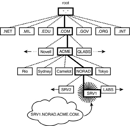
DNS naming operates similarly to fully distinguished naming in the eDirectory. In the IP world, an absolute (or fully qualified) DNS domain name is constructed by listing all domains on the path from the end device to the Root. Just like eDirectory, a period is used to delimit the labels in the domain name. For example, in Figure 6.3, the absolute domain name for the host SRV1 in NORAD is represented as: SRV1.NORAD.ACME.COM.
In this case, the interior nodes of the DNS tree (such as .COM and .ACME) do not represent network devices. Instead, they represent logical divisions of the DNS name space—analogous to logical containers in the Novell eDirectory tree.
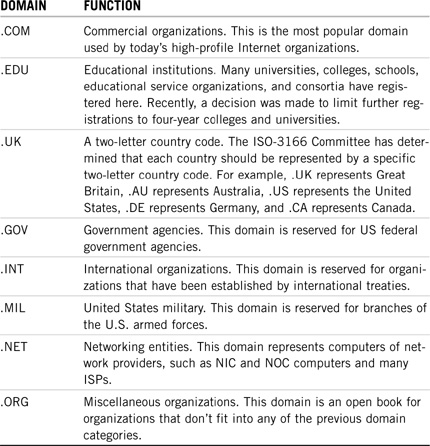
As you can see in Figure 6.3, many of the top-level domains have already been established by the Internet governing body, InterNIC. These predefined domains help organize the vast Internet into functional zones, as shown in Table 6.1. Note: This is only a partial list.
The DNS hierarchy can be further subdivided into partitions called zones. Zones begin at a specific domain and extend downward until they reach either a terminating host object or another zone. For example, the shaded area in Figure 6.4 represents the ACME.COM. zone. Furthermore, any private network (such as ACME.COM.) can implement its own domain names within the specific zone. Keep in mind that your zone must be sanctioned by the NIC to connect it to a public network such as the Internet.

This completes our discussion of the logical DNS hierarchy. As you can see, the virtual DNS tree resembles our own logical eDirectory cloud, but with a strange twist: The DNS tree is upside-down! From an organizational naming perspective, it seems pretty straightforward. Now let’s learn how DNS servers and clients resolve each other’s identities using name services.
REAL WORLD
DNS supports three different zone types:
![]() Standard zones—A standard DNS zone contains records that resolve domain names into IP addresses. Most of today’s Internet devices are addressed using standard DNS zoning rules.
Standard zones—A standard DNS zone contains records that resolve domain names into IP addresses. Most of today’s Internet devices are addressed using standard DNS zoning rules.
![]() IN-ADDR.ARPA zones—The IN-ADDR.ARPA. zone type provides mappings of IP addresses to domain names in a specific format: backward.
IN-ADDR.ARPA zones—The IN-ADDR.ARPA. zone type provides mappings of IP addresses to domain names in a specific format: backward.
![]() IP6.INT zones—The ever-increasing use of the Internet, along with the limited number of IP addresses, is driving the development of a new IP addressing scheme known as IPv6, which provides a greater quantity of unique IP addresses. Devices using this scheme in a zone of the Internet are part of an IP6.INT zone type.
IP6.INT zones—The ever-increasing use of the Internet, along with the limited number of IP addresses, is driving the development of a new IP addressing scheme known as IPv6, which provides a greater quantity of unique IP addresses. Devices using this scheme in a zone of the Internet are part of an IP6.INT zone type.
The second half of the DNS one-two punch is DNS Name Services. This is where the actual work is done. DNS Name Services actually maps user-friendly hostnames to IP addresses, and this helps computers throughout the Internet locate each other. As we mentioned earlier, DNS Name Services relies on a client/server architecture. In this model, clients (resolvers) query one or more servers for host address information. If the DNS server doesn’t have the information a client needs, it relays the request to another name server up or down the DNS hierarchy. As soon as it finds the answer it needs, the original DNS server relays it to the requesting client (resolver).
The names and IP addresses for all hosts in a DNS zone are maintained on a single server called the primary server. The information contained on the primary server is called the authoritative database for that zone. This database contains the following information:
![]() Names and addresses of all IP hosts within the domain
Names and addresses of all IP hosts within the domain
![]() Names of all subzones and addresses of the name servers for those zones
Names of all subzones and addresses of the name servers for those zones
![]() Addresses of name servers for the root domain and other zones within the domain (used to link your domain with the existing DNS hierarchy)
Addresses of name servers for the root domain and other zones within the domain (used to link your domain with the existing DNS hierarchy)
In Figure 6.5, we’ve set up the SRV1.NORAD.ACME.COM. server as the primary DNS server for the NORAD.ACME.COM. zone. All updates to the DNS database for the zone are made on this server.

TIP
It’s a good idea to keep the primary DNS server within your local zone; however, it’s not required. By rule, the DNS server for NORAD.ACME.COM. can be located anywhere in the DNS hierarchy.
Furthermore, DNS supports a backup naming server called a secondary server. Secondary DNS servers provide redundancy and load balancing for DNS naming within a zone. This backup periodically downloads a copy of the authoritative database from the primary server. It’s important to note that updates to the zone database are only made at the primary server and then distributed to the secondary server when it requests a copy. This process is known as zone transfer.
In Figure 6.5, we’ve configured SRV2.ACME.COM. as the secondary DNS server for the NORAD.ACME.COM. zone. As I’m sure you’ve noted, the secondary DNS server is located outside of its home zone. Although it’s a good idea to keep primary DNS servers inside the zone, you should distribute secondary DNS servers in geographically remote locations for fault tolerance purposes.
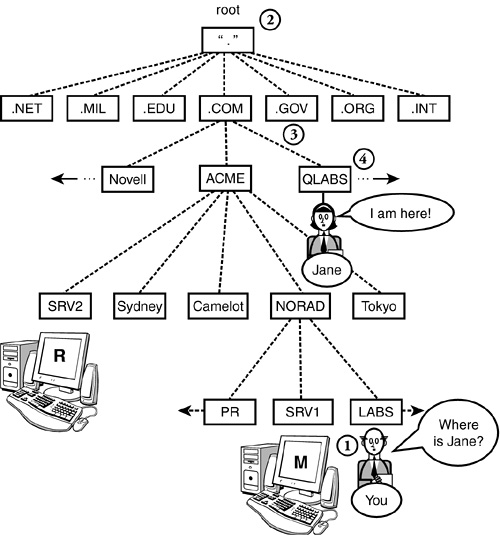
The process of DNS name resolution is actually quite similar to the way you might find a telephone number for someone who lives in a remote city. Let’s say, for example, you lived in NORAD and wanted to call someone in Tokyo. First, you would call your local operator to obtain the country code and the number for directory information in Japan. Then you would call directory information in Japan and get the local number for Tokyo. Then you would call Tokyo and query your friend by name. Let’s say you reside in the LABS division of NORAD within ACME. From your DNS client, you want to access a device in the QLABS.COM. zone. Here’s how your local DNS server would resolve the destination IP address (follow along in Figure 6.6):
![]() Point 1—To find a machine named JANE in the QLABS.COM. zone, you must first ask your local DNS server whether it has a cached entry for JANE. If not, your local primary server will relate the request to the root server.
Point 1—To find a machine named JANE in the QLABS.COM. zone, you must first ask your local DNS server whether it has a cached entry for JANE. If not, your local primary server will relate the request to the root server.
![]() Point 2—Your local primary DNS server asks the root DNS server for the location for the .COM server. At this point, you’ll begin resolving JANE’s IP address from the top down.
Point 2—Your local primary DNS server asks the root DNS server for the location for the .COM server. At this point, you’ll begin resolving JANE’s IP address from the top down.
![]() Point 3—Next, the .COM server will find the IP address of the primary server in the QLABS.COM. zone and send it to your local server.
Point 3—Next, the .COM server will find the IP address of the primary server in the QLABS.COM. zone and send it to your local server.
![]() Point 4—After your request finds its way to the primary DNS server in the QLABS.COM. zone, you’ll be able to resolve the specific IP address for JANE. This address will then be relayed back to your local primary DNS server (Point 1) by backtracking through all the servers (or routers) that it took to get there.
Point 4—After your request finds its way to the primary DNS server in the QLABS.COM. zone, you’ll be able to resolve the specific IP address for JANE. This address will then be relayed back to your local primary DNS server (Point 1) by backtracking through all the servers (or routers) that it took to get there.
As you can see, DNS is a powerful tool for helping users resolve complex IP addresses. Furthermore, the NetWare 6 DNS/DHCP implementation stores zone data within eDirectory and replicates it like other eDirectory data. Because of this, all NetWare servers can access DNS data from the eDirectory tree. This provides fault tolerance and load balancing for DNS data, and enables you to make changes to DNS zones from anywhere on the network.
Now let’s expand our DNS/DHCP journey into the realm of DHCP—the Dynamic Host Configuration Protocol.
Test Objective Covered:
![]() Identify How DHCP Services Work (3004)
Identify How DHCP Services Work (3004)
The next step in our elegant IP management ballet is communication. If you want a computer (or some other device) to function on a TCP/IP network, you must first configure it with a number of IP options. These options are small, but important, tidbits of data that help network devices communicate—such as a client’s own domain name, a client’s IP address, the DNS server’s IP address, the subnet mask, and so on. All computers must be aware of these facts to coexist peacefully on a TCP/IP network.
As you can see in Figure 6.7, DHCP is built on the client/server model. In this model, the server is a host that provides initialization parameters to clients using the DHCP protocol. Similarly, the client is an Internet host that requests parameters from the DHCP server. In this scenario, the DHCP server delivers host-specific configuration parameters and assigns network addresses.
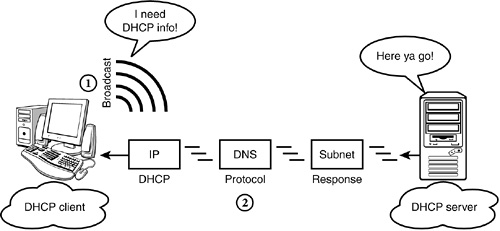
So, how does it work? In Figure 6.7, the DHCP client initiates a broadcast request by saying, “I need DHCP info!” In response, the DHCP server examines the request broadcast to determine which network segment it came from. If the DHCP server is configured to respond to that segment, it sends IP configuration data to the client.
In this model, IP addresses can be allocated to DHCP clients in one of three ways:
![]() Automatic allocation—DHCP assigns a permanent IP address to every host. By using this method, the server always assigns the same address to each host. This is sometimes referred to as a permanent assignment.
Automatic allocation—DHCP assigns a permanent IP address to every host. By using this method, the server always assigns the same address to each host. This is sometimes referred to as a permanent assignment.
![]() Dynamic allocation—DHCP assigns a temporary IP address to each host from an internal pool. This address is valid for a defined period of time, and it expires if the client doesn’t renew the address or if the server decides to let it expire. At that point, the client’s IP address returns to the pool for reassignment. This capability enables more efficient use of scarce IP addresses. However, it creates tremendous overhead if not configured properly. This is sometimes referred to as a leased assignment.
Dynamic allocation—DHCP assigns a temporary IP address to each host from an internal pool. This address is valid for a defined period of time, and it expires if the client doesn’t renew the address or if the server decides to let it expire. At that point, the client’s IP address returns to the pool for reassignment. This capability enables more efficient use of scarce IP addresses. However, it creates tremendous overhead if not configured properly. This is sometimes referred to as a leased assignment.
![]() Manual allocation—This requires you (the CNE) to assign IP addresses manually. With this method, DHCP simply delivers the address to the host upon connection. However, you have to do all the hard work!
Manual allocation—This requires you (the CNE) to assign IP addresses manually. With this method, DHCP simply delivers the address to the host upon connection. However, you have to do all the hard work!
Because DHCP requests are broadcasts that aren’t usually forwarded by routers, DHCP relies on a relay agent to get DHCP requests from one network segment to another. A relay agent is actually software that runs on the network segment where DHCP requests are originating; the agent forwards these requests to a DHCP server residing on a remote network segment. The relay agent then forwards the DHCP server response to the requesting workstation.
TIP
Novell’s implementation of a relay agent is BOOTPFWD.NLM. This must be loaded on a NetWare server and configured to forward DHCP requests to a remote DHCP server.
Fortunately, NetWare 6 uses eDirectory to help automate DHCP allocation. With eDirectory integration, IP addresses are stored in the central database for automatic or dynamic allocation. This prevents the single-point-of-failure problems experienced with other DHCP implementations. Thanks to NetWare 6, eDirectory ensures that DHCP provides managed IP addresses throughout the enterprise. Even more importantly, you can administer DHCP configurations as objects in the eDirectory tree.
Speaking of objects, let’s continue our NetWare 6 DNS/DHCP review with a description of NetWare 6’s 11 DNS/DHCP eDirectory objects.
Test Objectives Covered:
![]() Identify How DNS Services Work (3004) (continued)
Identify How DNS Services Work (3004) (continued)
![]() Identify How DHCP Services Work (3004) (continued)
Identify How DHCP Services Work (3004) (continued)
![]() Design and Implement an eDirectory DNS/DHCP Strategy (575)
Design and Implement an eDirectory DNS/DHCP Strategy (575)
NetWare 6 enables you to integrate DNS/DHCP services into eDirectory by extending the schema and creating new eDirectory objects. These objects represent a variety of IP entities, including DNS/DHCP servers, groups, zones, subnet pools, and resource records. Integrating these new objects into eDirectory simplifies your life and enables centralized configuration of the IP network. This is a good thing!
For you to become an IP management pro, you must understand the functionality of all 11 NetWare 6 DNS/DHCP eDirectory objects. These objects are organized into three “buckets”:
![]() Global DNS/DHCP objects—These objects are created automatically when you extend the eDirectory schema. This category includes three DNS/DHCP objects: DNSDHCP-GROUP, DNS-DHCP LOCATOR, and the RootServerInfo Zone.
Global DNS/DHCP objects—These objects are created automatically when you extend the eDirectory schema. This category includes three DNS/DHCP objects: DNSDHCP-GROUP, DNS-DHCP LOCATOR, and the RootServerInfo Zone.
![]() DNS objects—These objects enable you to manage domain name services from the central eDirectory. This category includes three eDirectory objects: DNS Zone, DNS Resource Record Sets (RRSet), and the DNS Name Server object.
DNS objects—These objects enable you to manage domain name services from the central eDirectory. This category includes three eDirectory objects: DNS Zone, DNS Resource Record Sets (RRSet), and the DNS Name Server object.
![]() DHCP objects—These objects enable you to assign IP addresses dynamically from the central eDirectory database. This category includes five DHCP objects: DHCP Server, DHCP Subnet, DHCP SAR, IP Address, and the Subnet Pool object.
DHCP objects—These objects enable you to assign IP addresses dynamically from the central eDirectory database. This category includes five DHCP objects: DHCP Server, DHCP Subnet, DHCP SAR, IP Address, and the Subnet Pool object.
Let’s take a much closer look at these 11 DNS/DHCP eDirectory objects, starting with the global objects.
TIP
Novell recommends that you place the DNS/DHCP objects very high in the eDirectory tree when you extend the schema. Doing so facilitates universal access to IP management data, such as IP addresses and configurations. For example, it’s recommended that you place the DNS/DHCP objects in a container no more than two levels below the tree root. Also consider partitioning the host container and replicating it to distributed, remote locations.
As soon as you extend the eDirectory schema, three global DNS/DHCP objects are created automatically. It’s important to note that only one group object and one locator can exist in any given eDirectory tree. Subsequently, the DNS servers, DHCP servers, and DNS/DHCP console tools must have access to these objects. The following is a brief description of the three global DNS objects created automatically during eDirectory schema extension:
![]() DNSDHCP-GROUP Group object—The DNSDHCP-GROUP object offers an easy method for providing the rights granted to new DNS/DHCP objects to other objects in the tree. By default, the DNSDHCP-GROUP object is given the Browse object right and the Supervisor property right to all new DNS and DHCP objects you create. This way you can guarantee access to DNS/DHCP information for any eDirectory object by simply assigning it as a member of the DNS/DHCP-GROUP object. NetWare servers that you designate as DNS and/or DHCP servers are automatically made members of this group.
DNSDHCP-GROUP Group object—The DNSDHCP-GROUP object offers an easy method for providing the rights granted to new DNS/DHCP objects to other objects in the tree. By default, the DNSDHCP-GROUP object is given the Browse object right and the Supervisor property right to all new DNS and DHCP objects you create. This way you can guarantee access to DNS/DHCP information for any eDirectory object by simply assigning it as a member of the DNS/DHCP-GROUP object. NetWare servers that you designate as DNS and/or DHCP servers are automatically made members of this group.
![]() DNS-DHCP Locator object—The DNS-DHCP Locator object contains global defaults and DHCP options. It also contains a list of all the DNS/DHCP entities in the tree, including servers, subnets, and zones. The purpose of the DNS-DHCP Locator object is to help you and your management tools find all the DNS/DHCP objects you need without having to search the entire eDirectory tree. (Note: The DNS-DHCP Locator object is not configurable; therefore, it isn’t displayed in ConsoleOne or iManager.)
DNS-DHCP Locator object—The DNS-DHCP Locator object contains global defaults and DHCP options. It also contains a list of all the DNS/DHCP entities in the tree, including servers, subnets, and zones. The purpose of the DNS-DHCP Locator object is to help you and your management tools find all the DNS/DHCP objects you need without having to search the entire eDirectory tree. (Note: The DNS-DHCP Locator object is not configurable; therefore, it isn’t displayed in ConsoleOne or iManager.)
![]() RootServerInfo Zone object—The RootServerInfo Zone object contains the IP addresses of the root servers on the Internet. It enables you to resolve domain names that belong to zones outside your current zone. Root servers are DNS servers that are maintained on the Internet as top-level phone books. The RootServerInfo Zone object is a portal to link you to the Internet so that your hosts can find other public zones.
RootServerInfo Zone object—The RootServerInfo Zone object contains the IP addresses of the root servers on the Internet. It enables you to resolve domain names that belong to zones outside your current zone. Root servers are DNS servers that are maintained on the Internet as top-level phone books. The RootServerInfo Zone object is a portal to link you to the Internet so that your hosts can find other public zones.
That completes our exploration of the three automatically created DNS/DHCP objects. In addition to these three, you can manually create eight other objects after you extend the schema. Let’s continue with a description of the three DNS eDirectory objects.
Three new DNS objects are available after you extend the eDirectory Schema. These objects help you centrally manage the relationship between DNS host naming and IP addressing. Later in this chapter, we’ll explore these objects in detail and learn how to create and configure them. For now, here’s a brief description:
![]() DNS Zone object—This is an eDirectory container that holds all the data for a single DNS zone. This is the quintessential DNS object. The DNS Zone object contains data that correlates to a variety of DNS-specific entities, including start of authority (SOA), resource records (RR), a list of all eDirectory servers that support the DNS Zone, and appropriate server information. It’s important to note that the DNS hierarchy is not represented within the eDirectory tree. A Zone object and its children, for example, might display as peers within eDirectory, even though they have a parent-child relationship in DNS.
DNS Zone object—This is an eDirectory container that holds all the data for a single DNS zone. This is the quintessential DNS object. The DNS Zone object contains data that correlates to a variety of DNS-specific entities, including start of authority (SOA), resource records (RR), a list of all eDirectory servers that support the DNS Zone, and appropriate server information. It’s important to note that the DNS hierarchy is not represented within the eDirectory tree. A Zone object and its children, for example, might display as peers within eDirectory, even though they have a parent-child relationship in DNS.
![]() DNS Server object—This is a separate logical entity from the standard NetWare 6 Server object. The DNS Server object carries out zone instructions and contains specific configuration parameters, including a zone list, DNS server IP address, DNS server domain name, server options, and a forwarding/no-forwarding list. This object can be housed within an Organization, Organizational Unit, Country, or Locality container.
DNS Server object—This is a separate logical entity from the standard NetWare 6 Server object. The DNS Server object carries out zone instructions and contains specific configuration parameters, including a zone list, DNS server IP address, DNS server domain name, server options, and a forwarding/no-forwarding list. This object can be housed within an Organization, Organizational Unit, Country, or Locality container.
![]() DNS Resource Record Set (RRSet) object—The DNS RRSet object contains all the Resource Records for a specific zone. Resource Record objects store naming data for each DNS server. It’s important to note that the RRSet is created automatically when you build one or more Resource Records. The RRSet contains the following DNS information: DNS domain name, a DNS address class, and a time-to-live (TTL) record. Finally, the DNS Resource Record object contains the Record type and data of its host RR.
DNS Resource Record Set (RRSet) object—The DNS RRSet object contains all the Resource Records for a specific zone. Resource Record objects store naming data for each DNS server. It’s important to note that the RRSet is created automatically when you build one or more Resource Records. The RRSet contains the following DNS information: DNS domain name, a DNS address class, and a time-to-live (TTL) record. Finally, the DNS Resource Record object contains the Record type and data of its host RR.
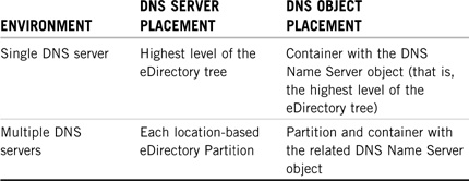
To prevent slow network performance because of traffic over WAN links, be sure to place DNS objects in the same partition as the DNS server. Table 6.2 shows some options for DNS server and object placement.
Now let’s complete our DNS/DHCP object lesson with the final five DHCP objects.
Five new DHCP objects are available after you extend the eDirectory Schema. These objects help you to centrally manage IP address assignments and subnet attributes. Later in this chapter, we’ll explore these objects in detail and learn how to create and configure them. For now, here’s a brief description:
![]() DHCP Server object—This represents the DHCP server and contains a multivalued attribute listing of the subnet ranges that this DHCP server is supporting. The DHCP Server object also contains all server-specific configuration and policy information. A DHCP Server object can be housed in an Organization, Organizational Unit, Country, or Locality container.
DHCP Server object—This represents the DHCP server and contains a multivalued attribute listing of the subnet ranges that this DHCP server is supporting. The DHCP Server object also contains all server-specific configuration and policy information. A DHCP Server object can be housed in an Organization, Organizational Unit, Country, or Locality container.
![]() DHCP Subnet object—This is the most fundamental DHCP object in the eDirectory tree. The Subnet object acts as a container for IP Address and SAR objects. A Subnet object’s specific DHCP options and configuration parameters apply to the entire subnet and override global options.
DHCP Subnet object—This is the most fundamental DHCP object in the eDirectory tree. The Subnet object acts as a container for IP Address and SAR objects. A Subnet object’s specific DHCP options and configuration parameters apply to the entire subnet and override global options.
![]() DHCP SAR object—This is the Subnet Address Range (SAR) object. The SAR is primarily used to identify a range of addresses (or pool) for dynamic address assignment or exclusion. Additionally, the SAR object stores the start of a hostname that can be assigned to clients when addresses are given. Typically, you should use multiple address ranges under a single Subnet object. This gives you the most flexibility for eDirectory DHCP IP address assignment.
DHCP SAR object—This is the Subnet Address Range (SAR) object. The SAR is primarily used to identify a range of addresses (or pool) for dynamic address assignment or exclusion. Additionally, the SAR object stores the start of a hostname that can be assigned to clients when addresses are given. Typically, you should use multiple address ranges under a single Subnet object. This gives you the most flexibility for eDirectory DHCP IP address assignment.
![]() IP Address object—This represents a single IP address. The IP Address object can be assigned manually, automatically, or dynamically. For dynamic or automatic assignment, DHCP creates an IP Address object under the subnet where the address is to be assigned. If you want to create this object manually, you must use the appropriate DNS/DHCP tool. When configuring an individual IP Address object, you can provide specific options that override any existing global or subnet parameters.
IP Address object—This represents a single IP address. The IP Address object can be assigned manually, automatically, or dynamically. For dynamic or automatic assignment, DHCP creates an IP Address object under the subnet where the address is to be assigned. If you want to create this object manually, you must use the appropriate DNS/DHCP tool. When configuring an individual IP Address object, you can provide specific options that override any existing global or subnet parameters.
![]() Subnet Pool object—This provides support for multiple subnets through a DHCP or BOOTP forwarder by identifying a pool of subnet addresses for remote address assignment. A Subnet Pool object can be housed in an Organization, Organizational Unit, Country, or Locality container.
Subnet Pool object—This provides support for multiple subnets through a DHCP or BOOTP forwarder by identifying a pool of subnet addresses for remote address assignment. A Subnet Pool object can be housed in an Organization, Organizational Unit, Country, or Locality container.
Determine DHCP object placement along with DHCP server placement. To avoid traffic over WAN links, choose a primary server at each location. Table 6.3 shows some options for DHCP server and object placement.

That completes our conceptual journey through the virtual world of NetWare 6 DNS/DHCP Services. In this lesson, you’ve learned how DNS servers translate complex numerical addresses into humane hostnames and how DHCP assigns IP information to IP clients. Don’t underestimate the administrative power of these two Internet protocols.
Is that enough conceptual overview? Are you ready to get to work? I hope so. Theory is important, but now it’s time for action. Next, we’ll tackle DNS/DHCP configuration.
After you’ve mastered the DNS/DHCP architecture and extended the eDirectory schema, it’s time to build customized functionality into your new IP management objects. In this lesson, we’ll focus on IP object configuration from both the DNS and DHCP perspectives.
If you selected DNS/DHCP Services when you installed NetWare 6, the key program files for Novell DNS/DHCP Services were automatically copied to the SYS: volume on your server. These files include program NLMs (which are copied to SYS:SYSTEM) and the DNS/DHCP Management Console setup program (which is copied to SYS:PUBLICDNSDHCP).
After Novell DNS/DHCP Services has been integrated into the eDirectory tree, you’ll have two graphical tools available for managing your IP network:
![]() DNS/DHCP Management Console—The DNS/DHCP Management Console is a graphical Java-based application that enables you to configure and to manage IP addresses and name services through eDirectory-based DNS and DHCP objects. The DNS/DHCP Management Console can be launched either from the Tools menu of NetWare Administrator or as a standalone utility on a Windows 95/98 or Windows NT/2000/XP/XP client through the DNSDHCP desktop shortcut.
DNS/DHCP Management Console—The DNS/DHCP Management Console is a graphical Java-based application that enables you to configure and to manage IP addresses and name services through eDirectory-based DNS and DHCP objects. The DNS/DHCP Management Console can be launched either from the Tools menu of NetWare Administrator or as a standalone utility on a Windows 95/98 or Windows NT/2000/XP/XP client through the DNSDHCP desktop shortcut.
![]() iManager—iManager provides the same DNS/DHCP administrative functions as the standalone Management Console, but without the restricting tether to a Novell client. Instead, iManager enables you to configure DNS and DHCP objects anytime, anywhere from a standard Web browser.
iManager—iManager provides the same DNS/DHCP administrative functions as the standalone Management Console, but without the restricting tether to a Novell client. Instead, iManager enables you to configure DNS and DHCP objects anytime, anywhere from a standard Web browser.
Now for the fun part! In the next lesson, we’ll use iManager to configure DNS for name/address translation and DHCP for IP address allocation.
TIP
To launch the DNS/DHCP Management Console from NetWare Administrator, use the Tools menu in the main eDirectory browser window. To launch the DNS/DHCP Management Console as a standalone executable, simply double-click the DNS/DHCP shortcut created on your Windows 95/98 or Windows NT/2000/XP/XP desktop during DNS/DHCP client installation.
Test Objective Covered:
![]() Configure DNS Services (3004)
Configure DNS Services (3004)
In the past, DNS was administered by building a large text database including all of a zone’s resource records. This traditional master/slave approach had several disadvantages, the most significant being that all changes were made at the master server (a single point of failure and performance bottleneck). Novell has solved many of these problems by integrating DNS into the eDirectory database.
By shifting control away from the primary and secondary servers, Novell enables DNS changes to occur anywhere in the network through eDirectory. This removes the single point of DNS failure: the traditional master server. Instead, zone data is stored within eDirectory and replicated just like any other data in the logical tree. To activate DNS Services on a Novell network, perform the following five configuration steps:
1. Create a DNS server—Create a DNS server that can respond to DNS queries within a given DNS zone (primary or secondary). This is a separate logical entity from the standard NetWare Core Protocol (NCP) Server object and can be created within an Organization, Organizational Unit, Country, or Locality container.
2. Configure a DNS Zone object—Configure a DNS Zone object to house all of the domain naming information contained within resource records. This is an eDirectory container that holds all the data for a single DNS zone. The DNS Zone object contains data that correlate to a variety of DNS-specific entities, including a list of all eDirectory-based servers that support the DNS zone, SOA, RRs, and associated server information.
NOTE
The hierarchy of DNS appears flat within the eDirectory tree. A Zone object and its children, for example, might display as peers within the eDirectory tree, even though they have a parent-child relationship within DNS.
3. Define resource records—Define the RRs that will contain the actual IP naming data for a given DNS zone. These leaf objects are placed in RRSet containers automatically. DNS Resource Record Set objects contain all the resource records for a specific zone. The RRSet contains the following DNS information: a DNS domain name, a DNS address class, and a TTL record. Finally, the DNS Resource Record object contains the record type and data of its host RR.
4. Activate the DNS server—Activate the DNS server on the NetWare 6 console by typing NAMED.
5. Configure DNS workstations—Configure distributed IP workstations so that they can resolve hostnames automatically using DNS.
TIP
Carefully study the four DNS objects (DNS Server, DNS Zone, Resource Record, and Resource Record Set) and understand the purpose of each. Specifically, know that the DHCP Zone object contains Resource Record and Resource Record Set objects. Also, be aware that a DNS server can be a primary or secondary server.
In this section, we’ll use iManager to accomplish these five DNS configuration steps. But first, we must establish a scope setting for this session so that iManager knows where to put the newly configured DNS objects. First, authenticate to iManager and select the Roles and Tasks icon in the header frame. You’re presented with four configuration links when you expand DNS Management in the navigation frame (see Figure 6.8). Choose DNS/DHCP Scope Settings and input a context for the DNS/DHCP Locator and Administrative Scope (such as .WHITE.CRIME.TOKYO.ACME).
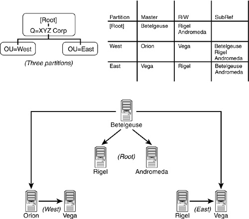
If you want a NetWare 6 server to obtain and update DNS data in the eDirectory tree, you must first create a corresponding DNS Server object. After you’ve create the server, it can be designated to service primary or secondary zones. A designated server is a NetWare 6 server that is assigned to obtain and update DNS data from a DNS Zone object. Novell DNS Services supports two different types of designated DNS servers:
![]() Primary designated server—If the DNS server services a primary zone, it performs the duties of a master DNS server. As a result, the DNS server will be able to query eDirectory to resolve names into IP addresses, update the zone’s serial number, and manage resource records.
Primary designated server—If the DNS server services a primary zone, it performs the duties of a master DNS server. As a result, the DNS server will be able to query eDirectory to resolve names into IP addresses, update the zone’s serial number, and manage resource records.
![]() Secondary designated server—If the DNS server services a secondary zone, it becomes a transition point between eDirectory and an external primary name server. For example, you can improve name resolution performance by creating a DNS Zone object that acts as a secondary to an ISP’s master name server. You can also create a secondary designated server that receives zone transfers from the ISP master name server and also places IP naming information in your eDirectory tree. These resource records would then be replicated throughout the network by eDirectory.
Secondary designated server—If the DNS server services a secondary zone, it becomes a transition point between eDirectory and an external primary name server. For example, you can improve name resolution performance by creating a DNS Zone object that acts as a secondary to an ISP’s master name server. You can also create a secondary designated server that receives zone transfers from the ISP master name server and also places IP naming information in your eDirectory tree. These resource records would then be replicated throughout the network by eDirectory.
To create a DNS Server object, follow these instructions (see Figure 6.9):
1. Authenticate to iManager, click on the Roles and Tasks icon, and expand DNS Management in the navigation frame.
2. Select the DNS Server Management link. Make sure that Create Server is selected, and then click OK.
3. Click the Browse button to select a host NetWare Server object for DNS activity. The default DNS server name will be the same as the selected eDirectory Server object, except with the following prefix: DNS_. You can modify the name of the DNS Server object later.
4. In the Domain Name field, type the name of the host domain for this DNS server. The domain might or might already exist in your eDirectory tree. Click Create to complete the process.
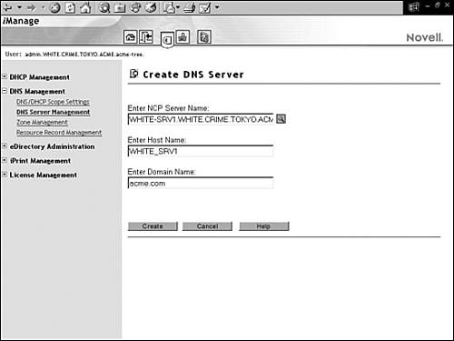
After you’ve created a DNS Server object, you must assign it to a primary or secondary DNS zone. At that point, the server becomes a primary or secondary designated server. To create a DNS Zone object, click the Zone Management link in the navigation frame of iManager. Next, make sure Create Zone is selected, and choose OK. After you do this, you’ll be greeted with the Create DNS Zone dialog box (shown in Figure 6.10):
![]() Create New Zone—At the top of the Create Zone dialog box, you’ll be asked to choose from three different zone types: Standard, INADDR. ARPA, or IP6.INT. Unless you have any special requirements, mark the Create New Zone radio button to define a Standard zone. (Note: You can create only one IP6.INT Zone object in a given eDirectory tree, so the Create IP6.INT box will be displayed only if an IP6.INT Zone object doesn’t already exist. All IP Version 6 addresses must be grouped under this object.)
Create New Zone—At the top of the Create Zone dialog box, you’ll be asked to choose from three different zone types: Standard, INADDR. ARPA, or IP6.INT. Unless you have any special requirements, mark the Create New Zone radio button to define a Standard zone. (Note: You can create only one IP6.INT Zone object in a given eDirectory tree, so the Create IP6.INT box will be displayed only if an IP6.INT Zone object doesn’t already exist. All IP Version 6 addresses must be grouped under this object.)
![]() Specify eDirectory Context—Next, you must specify a valid eDirectory context for the DNS Zone object. This context should match the highest point in the zone’s DNS hierarchy.
Specify eDirectory Context—Next, you must specify a valid eDirectory context for the DNS Zone object. This context should match the highest point in the zone’s DNS hierarchy.
![]() Enter Zone Domain Name—This identifies the specific subdomain for your zone. This name will be used both inside and outside eDirectory for zone transfers. If you specify a secondary zone type, the domain name must match the name of the domain being replicated from the primary name server.
Enter Zone Domain Name—This identifies the specific subdomain for your zone. This name will be used both inside and outside eDirectory for zone transfers. If you specify a secondary zone type, the domain name must match the name of the domain being replicated from the primary name server.
![]() Select Zone Type—All DNS Zone objects must be configured as either primary or secondary zones. By default, the Primary radio button is highlighted and all DNS resource records are distributed through eDirectory. However, you also have the option of using an outside (non-eDirectory) master server as your primary management point for DNS. If you retain the services of a non-eDirectory master server, you must create a secondary DNS Zone object to interface with eDirectory. In this case, the Zone object name must follow the specifications put forth by the master server. You’ll also need to provide the IP address of the master server in the Create Zone window. This allows the secondary Zone object to request updates from the non-eDirectory master and to distribute them throughout the network.
Select Zone Type—All DNS Zone objects must be configured as either primary or secondary zones. By default, the Primary radio button is highlighted and all DNS resource records are distributed through eDirectory. However, you also have the option of using an outside (non-eDirectory) master server as your primary management point for DNS. If you retain the services of a non-eDirectory master server, you must create a secondary DNS Zone object to interface with eDirectory. In this case, the Zone object name must follow the specifications put forth by the master server. You’ll also need to provide the IP address of the master server in the Create Zone window. This allows the secondary Zone object to request updates from the non-eDirectory master and to distribute them throughout the network.
![]() Enter Name Server IP Address—A DNS server must be assigned to a Zone object during zone creation. It can be either an existing DNS Server object or one that will be created later. To assign a DNS server that’s already defined in eDirectory, select it from the Assign Authoritative DNS Server list. If you haven’t created a DNS Server object yet, provide the hostname and domain information in the fields provided. When you create the designated DNS server, the Zone object will automatically find it. Finally, click Create to complete the process.
Enter Name Server IP Address—A DNS server must be assigned to a Zone object during zone creation. It can be either an existing DNS Server object or one that will be created later. To assign a DNS server that’s already defined in eDirectory, select it from the Assign Authoritative DNS Server list. If you haven’t created a DNS Server object yet, provide the hostname and domain information in the fields provided. When you create the designated DNS server, the Zone object will automatically find it. Finally, click Create to complete the process.

RRs are eDirectory leaf objects that contain the IP-based host information maintained by DNS name servers. In short, these are the DNS database. Each DNS zone must contain several types of resource records for DNS to function properly. The most common resource record types are
![]() Name server record (NS)—This RR replaces a domain name with a hostname for a specific DNS server. The Zone object must contain NS records for each primary and secondary server in the zone.
Name server record (NS)—This RR replaces a domain name with a hostname for a specific DNS server. The Zone object must contain NS records for each primary and secondary server in the zone.
![]() Canonical name record (CNAME)—This RR maps alias names to DNS names.
Canonical name record (CNAME)—This RR maps alias names to DNS names.
![]() Address record (A)—This RR provides the IP address for the zone. Each IP host uses the A record to map hostnames to IP addresses.
Address record (A)—This RR provides the IP address for the zone. Each IP host uses the A record to map hostnames to IP addresses.
![]() Mail eXchange record (MX)—This RR maps Simple Mail Transfer Protocol (SMTP) mail addresses to domain names.
Mail eXchange record (MX)—This RR maps Simple Mail Transfer Protocol (SMTP) mail addresses to domain names.
![]() Pointer record (PTR)—This RR maps IP addresses to host names within an IN-ADDR.ARPA zone and provides services for reverse lookups.
Pointer record (PTR)—This RR maps IP addresses to host names within an IN-ADDR.ARPA zone and provides services for reverse lookups.
To create a DNS Resource Record object, click on the Resource Record Management link in the navigation frame of iManager. Then make sure that the Create Resource Record box is marked, and click OK. At this point, you’ll be greeted with the Create Resource Record dialog box:
![]() Domain Name—In the Select Domain Name field, browse to the domain that you defined earlier when you created the Zone. The RR name should typically resemble the host object it is servicing and the host object’s predetermined function. For example, an A record for your new DNS Server object should be named DNS-SRV1-A.
Domain Name—In the Select Domain Name field, browse to the domain that you defined earlier when you created the Zone. The RR name should typically resemble the host object it is servicing and the host object’s predetermined function. For example, an A record for your new DNS Server object should be named DNS-SRV1-A.
![]() Resource Record Type—Select a resource record type and provide the necessary configuration information. By default, iManager creates an A record. If you want a CNAME record, you can highlight that choice or mark the Others check box to create an RR from a large list of supported types. The configuration information required for each RR depends on the type you choose. Finally, click Create to build the RR eDirectory object.
Resource Record Type—Select a resource record type and provide the necessary configuration information. By default, iManager creates an A record. If you want a CNAME record, you can highlight that choice or mark the Others check box to create an RR from a large list of supported types. The configuration information required for each RR depends on the type you choose. Finally, click Create to build the RR eDirectory object.
After you’ve created a Resource Record object, it will be placed in a corresponding RRSet container. The RRSet object is created automatically for each unique DNS zone. The resource record is designated Read Only, which means that you must delete the object and re-create it to make any modifications.
After you’ve created the DNS server and associated it with a new DNS zone, you must activate the DNS server. This is accomplished by typing the following command at the NetWare 6 server console:
NAMED
The following parameters are supported by this command:
![]() -a—Turns on auto-detect of new zones (default)
-a—Turns on auto-detect of new zones (default)
![]() -b—Turns off auto-detect of new zones
-b—Turns off auto-detect of new zones
![]() -f <script.txt> [context]—Creates multiple zones using a text file in BIND bootfile format; specifying the context enables zones to be created anywhere in the eDirectory tree
-f <script.txt> [context]—Creates multiple zones using a text file in BIND bootfile format; specifying the context enables zones to be created anywhere in the eDirectory tree
![]() -h—Displays help information
-h—Displays help information
![]() -l—Enables a DNS server to log in as an administrator to acquire rights required to create and delete zones from the command line
-l—Enables a DNS server to log in as an administrator to acquire rights required to create and delete zones from the command line
![]() -m <file.dat> [context]—Imports file.dat and creates a new primary zone; specifying the context enables zones to be created anywhere in the eDirectory tree
-m <file.dat> [context]—Imports file.dat and creates a new primary zone; specifying the context enables zones to be created anywhere in the eDirectory tree
![]() -q—Disables verbose mode for debug messages
-q—Disables verbose mode for debug messages
![]() -r <zone name>—Deletes and removes an existing zone from the zone database
-r <zone name>—Deletes and removes an existing zone from the zone database
![]() -rp <characters>—Replaces listed characters with a dash (-) in hostnames for which resource records are dynamically created
-rp <characters>—Replaces listed characters with a dash (-) in hostnames for which resource records are dynamically created
![]() -s [zone name]—Prints status information (zone name is optional)
-s [zone name]—Prints status information (zone name is optional)
![]() -u <file.dat>—Imports file.dat and updates the contents of a previously created zone
-u <file.dat>—Imports file.dat and updates the contents of a previously created zone
![]() -v—Enables verbose mode for debug messages
-v—Enables verbose mode for debug messages
![]() -zi <zone name>—Forces named zone for zone-in transfer
-zi <zone name>—Forces named zone for zone-in transfer
If you make any changes to your DNS Server object while NAMED.NLM is loaded, you’ll need to unload and reload the module for your changes to take effect. Finally, you should consider placing the NAMED statement in your DNS server’s AUTOEXEC.NCF file so that it loads automatically when the server is started.
TIP
Study the steps for creating DNS Zone objects using iManager. Also, be able to specify all required Zone properties, such as the zone name, the domain name, the zone type, and the designated DNS server. Finally, remember how to activate the DNS server at the NetWare server console (that is, by typing NAMED).
When the DNS server is running, you must configure the workstations to use DNS for automatic name resolution. This is accomplished by customizing the TCP/IP Protocol property within Network Neighborhood on Windows 95/98 and Windows NT/2000/XP clients:
1. Right-click the Network Neighborhood icon on a Windows 95/98 or Windows NT/2000/XP desktop. Next, select Properties from the pop-up menu that appears.
2. The Network window should appear with the Configuration tab activated. If this is a Windows 95/98 workstation, highlight the TCP/IP Protocol and click Properties. If this is a Windows NT/2000/XP workstation, right-click the Local Area Connection and select Properties. Then select the TCP/IP protocol and select Properties.
3. The TCP/IP Properties window will appear with seven tabs. When you click the DNS Configuration tab, you’ll be greeted with two radio buttons: Disable DNS and Enable DNS (shown in Figure 6.11).

4. To configure Windows-based DNS, first click the Enable DNS radio button. Next, provide a host and domain name for this client and build a DNS server search order. Finally, in the DNS Server Search Order field, enter the IP address of your DNS server and then click Add.
5. To close the Network Neighborhood window and save your new settings, simply click OK a few times and reboot the workstation.
All finished! Your NetWare 6 Novell clients are all ready to accept name resolution information from your new DNS server and, more importantly, your life as an IP administrator is getting much easier. Now let’s shift gears and install DHCP services for NetWare 6.
Test Objective Covered:
![]() Configure DHCP Services (3004)
Configure DHCP Services (3004)
![]() Configure Dynamic DNS Services (3004)
Configure Dynamic DNS Services (3004)
DHCP is built on a client/server model. In this model, the DHCP server provides initialization parameters to IP clients using the Dynamic Host Configuration Protocol. Novell’s DHCP solution hinges on integration with eDirectory. NetWare 6 uses eDirectory to help automate DHCP activities by storing IP addresses in the central Directory.
When configuring DHCP, the following options are essential to all networks:
![]() DHCP server management—If you don’t create a DHCP server, you cannot use DHCP services. This server contains all the subnets, address ranges, preferences, and other DHCP objects you might configure.
DHCP server management—If you don’t create a DHCP server, you cannot use DHCP services. This server contains all the subnets, address ranges, preferences, and other DHCP objects you might configure.
![]() Subnet management—You must create a subnet to represent the network IP address assigned to your physical network segment. The subnet contains IP address configuration information to be assigned to the nodes that reside on your IP network segment.
Subnet management—You must create a subnet to represent the network IP address assigned to your physical network segment. The subnet contains IP address configuration information to be assigned to the nodes that reside on your IP network segment.
![]() Address range management—An address range is required to indicate the IP addresses that the server will draw from when assigning IP addresses.
Address range management—An address range is required to indicate the IP addresses that the server will draw from when assigning IP addresses.
On more complex networks, you can choose to employ some of the following additional configuration options:
![]() Global DHCP Configuration—With these options, you can save management time by establishing global defaults, preferences, and configuration options. These options enable you to do the following: set, view, and modify global preferences; import a DHCP configuration (such as copying DHCP 2.0 and 3.0 files into the eDirectory database); and export a DHCP configuration (such as copying the eDirectory database to a text file).
Global DHCP Configuration—With these options, you can save management time by establishing global defaults, preferences, and configuration options. These options enable you to do the following: set, view, and modify global preferences; import a DHCP configuration (such as copying DHCP 2.0 and 3.0 files into the eDirectory database); and export a DHCP configuration (such as copying the eDirectory database to a text file).
![]() Scope Settings—This option enables you to set session specifications for the eDirectory context of the Locator object and the administrative scope of the session. If you specify the context of the Locator object at the beginning of the session, you eliminate the need to search for the object. Specifying the administrative scope restricts the retrieval of objects for viewing to the scope you specify.
Scope Settings—This option enables you to set session specifications for the eDirectory context of the Locator object and the administrative scope of the session. If you specify the context of the Locator object at the beginning of the session, you eliminate the need to search for the object. Specifying the administrative scope restricts the retrieval of objects for viewing to the scope you specify.
![]() Subnet Pool Management—With this option, you can assign multiple subnets to service DHCP requests for a network segment that has more than one IP subnet address configured on it.
Subnet Pool Management—With this option, you can assign multiple subnets to service DHCP requests for a network segment that has more than one IP subnet address configured on it.
![]() IP Address Management—This option enables you to manually assign an IP address to a specific computer or specifically exclude the assignment of an IP address. The IP Address object represents a single IP address and can be created only in Subnet object containers.
IP Address Management—This option enables you to manually assign an IP address to a specific computer or specifically exclude the assignment of an IP address. The IP Address object represents a single IP address and can be created only in Subnet object containers.
To activate DHCP Services on a Novell network, perform the following five sequential configuration steps after you’ve configured an appropriate scope:
1. Create a DHCP server—You must create and configure a DHCP server for dynamic or manual IP address assignment. This is where DHCP clients get their IP address information. The DHCP Server object contains all supported subnet address ranges, server-specific configuration information, and DHCP policies. You can create a DHCP Server object in an Organization, Organizational Unit, Country, or Locality container.
2. Configure subnet addresses—You must configure the IP address information that you want the server to hand out via the Subnet object. The DHCP Subnet is a container that holds Subnet Address Range and IP Address objects. A subnet’s specific DHCP options and configuration parameters apply to the entire subnet and override global options. You can create a DHCP Subnet and/or Subnet Pool object in an Organization, Organizational Unit, Country, or Locality container.
3. Assign addresses with SAR or IP address objects—You must configure the IP address information for dynamic assignment (using a SAR) or for manual assignment (using an IP Address object). The SAR object identifies a range of addresses available for dynamic assignment. Conversely, the IP Address object represents a single IP address on the network. This object can provide specific IP configurations to a workstation that override global or subnet settings.
4. Activate the DHCP server—You must activate the DHCP server as a parallel process on the NetWare 6 server console by typing DHCPSRVR.
5. Configure DHCP workstations—You must configure distributed IP workstations so that they can request IP address information from the DHCP server upon initialization.
In this section, we’ll use iManager to configure NetWare 6 DHCP. Just like DNS Services, DHCP supports global settings and requires an administrative scope. First, authenticate to iManager and select the Roles and Tasks icon in the header frame. Next, you’ll be presented with seven configuration links when you expand DHCP Management in the navigation frame (see Figure 6.12). Finally, choose DNS/DHCP Scope Settings and input a context for the DNS/DHCP Locator object and Administrative Scope (such as .TOKYO.ACME).

Now let’s use our new scope to configure NetWare 6 DHCP Services.
To create a DHCP Server object, follow these instructions (follow along with Figure 6.13):
1. Authenticate to iManager, click on the Roles and Tasks icon, and expand DHCP Management in the navigation frame.
2. Select the DHCP Server Management link. Make sure that Create Server is selected, and then click OK.
3. Click the Browse button to select a host NetWare Server object for DHCP activity. The default DHCP server name will be the same as the selected eDirectory Server object, except with this prefix: DHCP_. You can modify the name of the DNS Server object later by using the Modify DHCP Server link. Finally, click Create to complete the process.
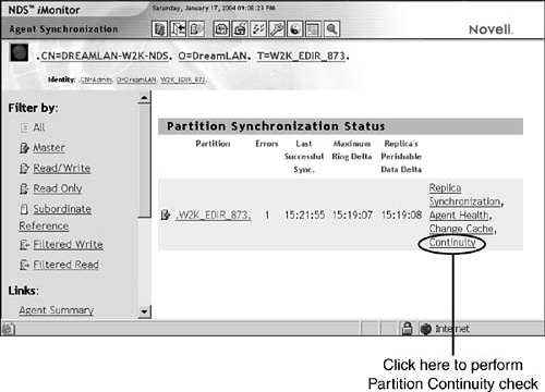
When your DHCP Server object is alive, you must configure IP addresses for automatic, dynamic, and manual distribution. Let’s start with a Subnet container in which we can store our SAR and IP Address objects.
The DHCP Subnet object is a container that holds all the SAR and IP Address objects for a physical network segment. To create a DHCP Subnet object, click on the Subnet Management link in the navigation frame of iManager. Then check the Create Subnet box and click OK. Finally, you’re greeted with the Create Subnet dialog box (shown in Figure 6.14):
![]() Enter Subnet Name—Each Subnet object must have a unique eDirectory name. The Subnet creation process will fail if you name the object the same as any other eDirectory object in the same container.
Enter Subnet Name—Each Subnet object must have a unique eDirectory name. The Subnet creation process will fail if you name the object the same as any other eDirectory object in the same container.
![]() Enter eDirectory Context—This is the full, distinguished name of the eDirectory container where the Subnet object resides. Typically, it’s the same container that holds the new DHCP server. You can accept the default context or browse to another container using the Browse button to the right of this input field.
Enter eDirectory Context—This is the full, distinguished name of the eDirectory container where the Subnet object resides. Typically, it’s the same container that holds the new DHCP server. You can accept the default context or browse to another container using the Browse button to the right of this input field.
![]() Enter Subnet IP Address—This identifies the actual IP address of the subnet’s logical network segment. Remember that the purpose of a Subnet object is to group SAR and IP Address objects according to the physical segmentation of your network. Make sure that you input the appropriate physical IP address in dotted-decimal notation.
Enter Subnet IP Address—This identifies the actual IP address of the subnet’s logical network segment. Remember that the purpose of a Subnet object is to group SAR and IP Address objects according to the physical segmentation of your network. Make sure that you input the appropriate physical IP address in dotted-decimal notation.
![]() Enter Subnet Mask—This is a filter that’s used to determine which subnet an IP address belongs to. The subnet mask determines the IP address class and subnetting strategy.
Enter Subnet Mask—This is a filter that’s used to determine which subnet an IP address belongs to. The subnet mask determines the IP address class and subnetting strategy.
![]() Select Default DHCP Server—Finally, you have to specify a default DHCP server for subnet address assignment. You can accept the default server or choose from a pull-down list. Click Create to complete the creation process.
Select Default DHCP Server—Finally, you have to specify a default DHCP server for subnet address assignment. You can accept the default server or choose from a pull-down list. Click Create to complete the creation process.
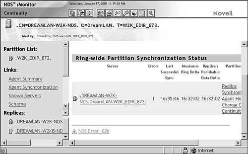
In addition, Novell supports the configuration of multiple IP subnet addresses for a single physical network segment. This is accomplished by using the DHCP Subnet Pool object. First create multiple Subnet objects within a single eDirectory context. Then use iManager to create a Subnet Pool object and add multiple Subnet objects to the pool.
After you’ve created the DHCP server and subnet, you must prepare the IP addresses for assignment. This can be accomplished using either of the following two DHCP objects:
![]() SAR (Subnet Address Range)—For dynamic address assignment to a group of workstations or a specific machine
SAR (Subnet Address Range)—For dynamic address assignment to a group of workstations or a specific machine
![]() IP Address—For manual address assignment to a specific machine
IP Address—For manual address assignment to a specific machine
The SAR object identifies a range of IP addresses available for dynamic assignment. It can also be configured to exclude a range of addresses from the automatic pool.
To create a SAR object, click on the Address Range Management link in the navigation frame of iManager. Then check the Create Address Range box and click OK. Next, the Create Address Range dialog box appears:
![]() Address Range Name—Each subnet range must have a unique name to identify it within the physical subnet segment. If you define multiple SARs within a single subnet, you might need to determine a distinguishing characteristic for each name.
Address Range Name—Each subnet range must have a unique name to identify it within the physical subnet segment. If you define multiple SARs within a single subnet, you might need to determine a distinguishing characteristic for each name.
![]() Start Address—This identifies the specific IP address that starts the SAR.
Start Address—This identifies the specific IP address that starts the SAR.
![]() End Address—Similarly, you must define an ending IP address for the second boundary of your SAR. The address ranges of SAR objects cannot overlap with each other. Furthermore, you must use contiguous and unassigned network addresses for each SAR within a subnet. Click Create and then OK to complete the SAR creation process.
End Address—Similarly, you must define an ending IP address for the second boundary of your SAR. The address ranges of SAR objects cannot overlap with each other. Furthermore, you must use contiguous and unassigned network addresses for each SAR within a subnet. Click Create and then OK to complete the SAR creation process.
The IP Address object enables you to override dynamic SAR addresses and to manually assign (or exclude) a specific IP address to (or from) a specific machine on the network. This is accomplished in two steps. First, create an IP Address object within an existing subnet by using the IP Address Management link in the navigation frame of iManager. Then associate the IP Address object with a specific machine’s Media Access Control (MAC) address using the IP Address field. Select Create and click OK to complete the IP Address object creation process.
TIP
For every Subnet object you create, two IP Address objects are automatically created. These two objects are exclusions for the IP addresses of 0 and 255. These exclusions are created because most TCP/IP stacks do not allow the assignment of either of these two addresses to hosts (0 is usually reserved for the network address and 255 is usually used as a broadcast address).
After you create the DHCP server and configure its IP information via Subnet, SAR, and IP Address objects, you must activate the DHCP server. This is accomplished by typing the following command at the NetWare 6 server console prompt:
DHCPSRVR
When DHCPSRVR.NLM is loaded, it reads IP address configuration data from eDirectory and loads the information into the server’s cache. Also, you should consider placing the DHCPSRVR statement in your DHCP server’s AUTOEXEC.NCF file so that it loads automatically when the server is started. Now the server is ready to hand out IP addresses to DNS/DHCP clients. The clients will not be ready to request the IP address information, however, until they have been properly configured.
When the DHCP server is running, you must configure the DHCP workstations to automatically accept IP configuration information. This is accomplished by customizing the TCP/IP Protocol property within Network Neighborhood on Windows 95/98 clients:
1. Right-click the Network Neighborhood icon on a Windows 95/98 desktop. Then click Properties in the pop-up menu that appears.
2. The Network window should appear, with the Configuration tab activated. Highlight the TCP/IP protocol and click Properties.
3. A TCP/IP Properties window will appear with seven tabs (shown in Figure 6.15). When you click the IP Address tab, you’ll be greeted with two radio buttons that enable you to specify whether the client will obtain an IP address automatically or specify an IP address

4. To configure a Windows 95/98 workstation for automatic address assignment, mark the Obtain an IP Address Automatically radio button. If the workstation previously had an IP address that was configured manually, you’ll be asked whether you want to enable DHCP at this point. If so, click Yes.
5. To close the Network Neighborhood window and save your new settings, simply click OK a few times and reboot the workstation. All finished! Now your NetWare 6 Novell clients are ready to surf the Web and, more importantly, your DHCP server will be handing out IP addresses automatically.
We’re almost finished, but no plan would be complete without some polish. Let’s take a look at a feature that could make your life as a network administrator so much easier: Dynamic DNS (DDNS).
Dynamic DNS (DDNS) combines the best of DHCP services with DNS. It enables DNS databases to be instantly notified and updated with address assignments made by DHCP services. If you’re planning to implement DNS and DHCP on your network, you should consider implementing DDNS. Although users gain access to resources using DNS, the administrator who has implemented DDNS does not face the error-prone and time-consuming task of manually assigning and maintaining IP addresses.
The capability of DDNS to dynamically assign available IP addresses to clients means that a client with a specific hostname won’t be forced to always have the same IP address. Although DNS servers furnish the current address for any hostname provided to a resolver, they must be manually updated with changes in address assignments.
Regardless of how often or how quickly an administrator can update the DNS database, it can still be out of sync with current host assignments. When addresses are assigned to individual devices, the DNS database obviously must be updated so that the new addresses can be resolved with the corresponding hostnames. This is required whether the hostname is assigned to the node dynamically or the device provides its own name to be bound to the assigned address.
Hostnames and IP addresses are basically different forms of the same essential information. Because of this, services that manage names and addresses should be integrated using DDNS. One way to do this is for the DHCP server to modify or delete the appropriate resource records in the DNS database so that both name-to-address and address-to-name resolutions can be made. The DNS/DHCP implementation used by Novell supports DDNS by updating DNS with information about addresses assigned and unassigned.
Enabling DDNS is as simple as 1-2-3. Follow these steps to enable DDNS:
1. Specify a zone reference in the Subnet object so that the DHCP server can determine which zone to update.
2. Configure the subnet address range as Dynamic DHCP or Dynamic BOOTP and DHCP range type.
3. Configure the Subnet Address Range with the Always Update parameter set to On.
After you’ve completed these steps, the DHCP server updates the DNS server for the zone by adding or deleting the corresponding A and PTR records. When leases expire, the DHCP server notifies the DNS server, causing the A and PTR records to be deleted. If a lease is renewed, nothing happens because no action is required.
You can configure DHCP to dynamically update DNS with the following two options:
![]() Global preference option—With this option, DHCP updates DNS for all subnets that the DHCP server services.
Global preference option—With this option, DHCP updates DNS for all subnets that the DHCP server services.
![]() Subnet configuration option—With this option, DNS is dynamically updated only for a specified subnet.
Subnet configuration option—With this option, DNS is dynamically updated only for a specified subnet.
Our journey through IP management started with the DNS hierarchy and DNS Name Service via DNS servers and resolvers. Then we explored the fundamental architecture of DHCP, and you learned how it facilitates IP address distribution. Furthermore, you were introduced to a powerful anytime, anywhere tool for IP administration: iManager. With it, you learned how to extend the eDirectory schema, build DNS/DHCP objects, and automated much of the pain usually associated with IP-based networks.
Now let’s tackle NetWare 6 DNS/DHCP in the real-life ACME universe with Lab Exercise 6.1. Then you’ll learn how to expand IP networking into the realm of private and public networks using Network Address Translation (NAT).
In this lab exercise, you will perform these advanced CNE IP management tasks:
![]() Extend the eDirectory Schema for DNS/DHCP
Extend the eDirectory Schema for DNS/DHCP
![]() Configure DNS Services in NetWare 6
Configure DNS Services in NetWare 6
![]() Configure DHCP Services in Netware 6
Configure DHCP Services in Netware 6
![]() Configure a Workstation to Use DHCP Services
Configure a Workstation to Use DHCP Services
In this lab exercise, you’ll need these components:
![]() WHITE-SRV1 server created in Lab Exercise 1.1
WHITE-SRV1 server created in Lab Exercise 1.1
![]() Workstation running Windows 95/98 or Windows NT/2000/XP
Workstation running Windows 95/98 or Windows NT/2000/XP
Perform the following tasks at the WHITE-SRV1 server console:
1. Mount the CD drive as a volume:
a. Place the NetWare 6 Operating System CD in the server’s CD drive.
b. At the server console prompt, enter CDROM.
2. On the NetWare 6 GUI screen, select Novell | Install.
3. When the Installed Products window appears, select Add.
4. When the Source Path window appears
a. Browse to the root of the CD.
b. Select PRODUCT.INI.
c. Select OK.
5. When the Source Path window reappears, select OK.
6. Wait while files are copied and the Installation Wizard is installed.
7. When the Components window appears
b. Select Novell DNS/DHCP Services.
c. Select Next.
8. If prompted, authenticate to eDirectory as admin.
9. When the LDAP Configuration window appears, select Allow Clear Text Passwords, and then select Next.
10. When the Summary window appears, review the information on the screen, and then select Finish. Wait while files are copied.
11. When the Installation Complete window appears, select Close.
12. Restart your server.
Perform the following tasks at your administrative workstation:
1. Open NetWare 6 Web Manager:
a. Open Internet Explorer.
b. In the Address field, enter your server’s IP address. If you’re using the IP addresses in this book, enter
https://192.168.1.81:2200
c. When the NetWare Web Manager window appears, in the eDirectory iManage field, select WHITE-SRV1.
2. When the Login screen appears, authenticate as Admin.
3. In the navigation frame on the left side of the screen, expand DNS Management.
4. Make DNS Scope Settings assignments:
a. In the navigation frame on the left, select DNS/DHCP Scope Settings.
b. When the DNS/DHCP Scope Settings window appears in the main context frame
![]() In the Context of DNS/DHCP Locator Object field, browse to and select the WHITE container.
In the Context of DNS/DHCP Locator Object field, browse to and select the WHITE container.
![]() In the Administrative Scope field, browse to and select the WHITE container.
In the Administrative Scope field, browse to and select the WHITE container.
![]() Click OK.
Click OK.
c. When informed that the Set Scope request succeeded, click OK.
5. Create a DNS Server object for your server:
a. In the navigation frame on the left side of the screen, select DNS Server Management.
b. When the DNS Server Management window appears in the main content frame, verify that Create Server is selected, and then select OK.
c. When the Create DNS Server window appears in the main content frame:
![]() In the Enter NCP Server Name field, browse to and select WHITE-SRV1.
In the Enter NCP Server Name field, browse to and select WHITE-SRV1.
![]() In the Enter Host Name field, enter WHITE-SRV1.
In the Enter Host Name field, enter WHITE-SRV1.
![]() In the Domain Name field, enter acme.com.
In the Domain Name field, enter acme.com.
![]() Select Create.
Select Create.
d. When informed that your Create request is successful, select OK.
6. Create a DNS Zone object:
a. In the navigation frame on the left side of the screen, select Zone Management.
b. When the Zone Management window appears in the main context frame, verify that Create New Zone is selected, and then click OK.
c. When the Create DNS Zone window appears in the main context frame
![]() In the Select Zone Type field, verify that Create New Zone is selected.
In the Select Zone Type field, verify that Create New Zone is selected.
![]() In the Specify eDirectory Context field, browse to and select WHITE.
In the Specify eDirectory Context field, browse to and select WHITE.
![]() In the Enter Zone Domain Name field, enter acme.com.
In the Enter Zone Domain Name field, enter acme.com.
![]() In the Select Zone Type field, verify that Primary is selected.
In the Select Zone Type field, verify that Primary is selected.
![]() In the Select Assigned Authoritative Zone Server field, select DNS-WHITESRV1. WHITE.CRIME.TOKYO.ACME.
In the Select Assigned Authoritative Zone Server field, select DNS-WHITESRV1. WHITE.CRIME.TOKYO.ACME.
![]() Select Create.
Select Create.
d. When informed that your Create DNS Zone request succeeded, click OK.
7. Create an IN-ADDR.ARPA zone object:
a. In the navigation frame on the left side of the screen, select Zone Management.
b. Make sure that Create New Zone is selected; then select OK.
c. When the Create DNS Zone window appears in the main context frame
![]() In the Select Zone Type field, select Create IN-ADDR ARPA.
In the Select Zone Type field, select Create IN-ADDR ARPA.
![]() In the Specify eDirectory context field, browse to and select WHITE.
In the Specify eDirectory context field, browse to and select WHITE.
![]() In the Zone Domain field, delete any 0s and enter 192.168.1.0.
In the Zone Domain field, delete any 0s and enter 192.168.1.0.
![]() In the Select Zone Type field, verify that Primary is selected.
In the Select Zone Type field, verify that Primary is selected.
![]() In the Select Assigned Authoritative Zone Server field, select DNS-WHITESRV1. WHITE.CRIME.TOKYO.AMCE.
In the Select Assigned Authoritative Zone Server field, select DNS-WHITESRV1. WHITE.CRIME.TOKYO.AMCE.
![]() Select Create.
Select Create.
d. When informed that the Create Zone request succeeded, click OK.
e. Close Internet Explorer.
8. Start the DNS service:
a. Open Internet Explorer.
b. In the address field, enter your server’s IP address. If you are using the IP addresses in this book, enter
https://192.168.1.81:2200
c. When the NetWare Web Manager window appears, in the NetWare Remote Manager field, select WHITE-SRV1.
d. When the “Enter Network Password” window appears, authenticate as Admin (using the full distinguished name).
e. In the navigation frame on the left side of the screen, under Manage Server, select Console Screens.
f. In the main content frame, under Current Screens, select Console Screens.
g. When the WHITE_SRV1 - NWScreen_Applet – Microsoft Internet Explorer Window appears, select Screen List.
h. When the Select Screen to View prompt appears, view the system console by entering 1.
i. At the NetWare server console prompt, enter NAMED.
j. From the Console Screens applet window, select Screen List.
k. When the Select Screen to View prompt appears, view the system console by entering 1.
l. When the AUTOEXEC.NCF file appears:
![]() Add NAMED after the STARTX command.
Add NAMED after the STARTX command.
![]() Press Esc; then select Yes to save changes.
Press Esc; then select Yes to save changes.
m. Close the Console Screen applet.
n. Close Internet Explorer.
Perform the following tasks at your administrative workstation:
1. Open NetWare 6 Web Manager:
a. Open Internet Explorer.
b. In the address field, enter your server’s IP address. If you are using the IP addresses in this book, enter
https://192.168.1.81:2200
c. When the NetWare Web Manager window appears, in the eDirectory iManage field, select WHITE-SRV1.
2. When the Login screen appears, authenticate as Admin.
3. Make DHCP Scope Settings assignments:
a. When the iManage window appears in the main context frame, in the navigation frame on the left side of the screen, expand DHCP Management.
b. In the navigation frame on the left side of the screen, select DNS/DHCP Scope Settings.
c. When the DNS/DHCP Scope Settings window appears in the main context frame
![]() In the Context of DNS/DHCP Locator Object field, browse to and select the WHITE container.
In the Context of DNS/DHCP Locator Object field, browse to and select the WHITE container.
![]() In the Administrative Scope field, browse to and select the WHITE container.
In the Administrative Scope field, browse to and select the WHITE container.
![]() Select OK.
Select OK.
d. When the Set Scope request succeeds, select OK.
4. Create a DHCP server:
a. In the navigation frame on the left side of the screen, select DHCP Server Management.
b. When the DHCP Server Management window appears in the main context frame, verify that Create Server is selected, and then select OK.
c. When the Create DHCP Server window appears in the main context frame, in the Enter NCP Server Name field, browse to and select WHITE-SRV1, and then select Create.
d. When informed that your Create DHCP Server request succeeded, select OK.
5. Configure the DHCP server to ping before sending IP addresses:
a. In the navigation frame on the left side of the screen, select DHCP Server Management.
b. When the DHCP Server Management window appears in the main context frame, select Modify Server, and then select OK.
c. When the first Modify DHCP Server window appears in the main context frame, verify that DHCP_WHITESRV1. WHITE.CRIME.TOKYO.ACME is selected, and then select OK.
d. When the second Modify DHCP Server window appears, select Next.
e. When the third Modify DHCP Server window appears, scroll to the bottom and mark Select Ping Enable, and then select Done.
f. When informed that the Modify request succeeded, select OK.
6. Create a Subnet object:
a. In the navigation frame on the left side of the screen, select Subnet Management.
b. When the Subnet Management window appears in the main context frame, verify that Create Subnet is selected, and then select OK.
c. When the Create Subnet window appears in the main context frame
![]() In the Enter Subnet Name field, enter NetWareSubnet.
In the Enter Subnet Name field, enter NetWareSubnet.
![]() In the Enter eDirectory Context field, browse to and select WHITE.
In the Enter eDirectory Context field, browse to and select WHITE.
![]() In the Enter Subnet IP Address field, enter 192.168.1.0.
In the Enter Subnet IP Address field, enter 192.168.1.0.
![]() In the Enter Subnet Mask field, enter 255.255.255.0.
In the Enter Subnet Mask field, enter 255.255.255.0.
![]() In the Select Default DHCP Server field, select DHCP_WHITE-SRV1.WHITE.CRIME.TOKYO.ACME.
In the Select Default DHCP Server field, select DHCP_WHITE-SRV1.WHITE.CRIME.TOKYO.ACME.
![]() Select Create.
Select Create.
d. When informed that the create subnet request succeeded, select OK.
7. Create a Subnet Range object that assigns the IP address range:
a. In the navigation frame on the left side of the screen, select Address Range Management.
b. When the Subnet Address Range Management window appears in the main content frame, verify that Create Address Range is selected, and then select OK.
c. When the Create Address Range window appears in the main content frame
![]() In the Enter Address Range Name field, enter Available Addresses.
In the Enter Address Range Name field, enter Available Addresses.
![]() In the Start Address field, enter 192.168.1.31.
In the Start Address field, enter 192.168.1.31.
![]() In the End Address field, enter 192.168.1.70.
In the End Address field, enter 192.168.1.70.
![]() Select Create.
Select Create.
d. When informed that the Subnet Address Range request succeeded, select OK.
e. Close Internet Explorer.
8. Start the DHCP server:
a. Open Internet Explorer.
b. In the Address field, enter your server’s IP address. If you are using the IP addresses in this book, enter
https://192.168.1.81:2200
c. Continue past the security alert screens to the NetWare Web Manager window, and select WHITE-SRV1 in the NetWare Remote Manager field. Authenticate to the Remote Manager utility.
d. In the navigation frame on the left side of the screen, under Manage Server, select Console Screens.
e. In the Main Content frame, select Console Screens.
f. In the Console Screens applet window, select Screen List.
g. Enter 1.
h. From the server console of WHITE-SRV1, enter DHCPSRVR.
i. From your server console:
![]() Enter EDIT AUTOEXEC.NCF.
Enter EDIT AUTOEXEC.NCF.
![]() Add DHCPSRVR after the MOUNT ALL command.
Add DHCPSRVR after the MOUNT ALL command.
![]() Press Esc, and then select Yes to save changes.
Press Esc, and then select Yes to save changes.
Perform the following tasks at your administrative workstation:
1. Configure TCP/IP for DHCP Services:
NOTE
The Course 3004 courseware assumes that you’re using a Windows 2000/XP workstation. If you’re using a different workstation operating system, you’ll have to modify the procedures accordingly. (For example, in Windows 98, you’ll have to access the Network icon in the Control Panel.)
a. On your desktop, right-click My Network Places, and then select Properties.
b. Right-click Local Area Connection, and then select Properties.
c. When the Local Area Connection Properties dialog box appears, select Internet Protocol (TCP/IP), and then select Properties.
d. When the Internet Protocol (TCP/IP) Properties dialog box appears
![]() Select Obtain an IP Address Automatically
Select Obtain an IP Address Automatically
![]() Select Obtain a DNS Server Address Automatically
Select Obtain a DNS Server Address Automatically
e. Close all Properties windows by selecting OK twice.
f. Select Start, Programs, Accessories, Command Prompt.
g. From the command prompt, enter IPCONFIG /RELEASE.
h. From the console prompt, enter IPCONFIG /RENEW.
i. Note that your new IP address falls within the range you configured when setting up DHCP.
j. Close the command prompt window by entering EXIT.
Test Objective Covered:
![]() Create a Private Network Using NAT (3004)
Create a Private Network Using NAT (3004)
With the growth of the Internet and corporate use of IP addresses, you could quickly run out of registered IP addresses for your organization. Fortunately, NetWare 6 provides a feature called Network Address Translation (NAT) as a strategy to create a private network and, thus, conserve valuable IP addresses. Simply stated, NAT enables private IP intranetworks to use nonregistered IP addresses internally and registered IP addresses externally (via the Internet).
TIP
For purposes of this discussion, think of a public network as one that uses globally unique, registered IP addresses. Every IP address must be unique from every other IP address on the same network. A private network, on the other hand, uses IP addresses that are not globally unique (that is, they’re unregistered). Because of this, a private network cannot be connected to the Internet.
NAT operates on a router connecting two networks together. It translates the local private IP addresses into registered external IP addresses before packets are forwarded on to the Internet. In addition, NAT serves as a firewall by keeping individual IP addresses on your local network hidden from the outside world. In this configuration, NAT advertises only one address for the entire network to the public Internet. (Note: NAT only provides protection at the Network layer of the OSI model and, therefore, should not be considered a total firewall solution.)
REAL WORLD
To determine which IP address to assign to private hosts when NAT is used, Novell recommends that you follow the addressing guidelines presented in RFC 1918. RFC 1918 explains that the Internet Assigned Numbers Authority (IANA) has reserved the following three blocks of IP addresses for private networks:
![]() 10.0.0.0–10.255.255.255 (a single Class A network number)
10.0.0.0–10.255.255.255 (a single Class A network number)
![]() 172.16.0.0– 172.31.255.255 (a set of 16 continuous Class B network numbers)
172.16.0.0– 172.31.255.255 (a set of 16 continuous Class B network numbers)
![]() 192.168.0.0–192.168.255.255 (a set of 256 continuous Class C network numbers)
192.168.0.0–192.168.255.255 (a set of 256 continuous Class C network numbers)
Any private network can use these addresses without coordination with IANA. These addresses are often referred to as nonroutable addresses because backbone routers on the Internet have filters that prevent them from being forwarded.
For smaller companies, the entire network can be configured as a private network connecting to the Internet through a single NAT router (which is basically a NetWare server on which you’ve configured NAT). A NAT router must have two network boards to connect two networks: One board connects to the private network, and one connects to the public network.
This enables you to provide Internet access to your entire network using only one registered IP address. For larger companies, individual intranets should be configured as private networks connected by multiple NAT routers and a registered IP backbone.
In either case, you must consider the following NAT limitations before you begin configuring your NAT routers: NAT does not support applications that embed an IP address in the data portion of the TCP/IP packet, and multicast and broadcast packets are not translated.
When an IP packet arrives into the NAT router from a host on a private network, it replaces the private IP address with a public IP address. The NAT router then forwards the packet to the public network. This also works in reverse. That is, packets coming into the NAT router from the public network have the public address replaced with a private IP address, and the packet is forwarded to the private network.
Because of its address translation role, NAT must reside between the public and private network boards. Each of these boards must have a private IP address assigned to it. Any addresses assigned to the public board must be your registered, public addresses.
NAT uses port numbers to track each private network host for which it has translated an IP packet. NAT tracks each private network host so that public hosts can respond to packets from private hosts. When the public host’s response goes back to the private host, the public host is aware of only the public IP address that NAT put into the packet.
NAT can be configured to operate in one of three modes:
![]() Dynamic Only—In this mode, NAT enables IP hosts on a private network to access the public network (such as the Internet) without requiring an administrator to assign a globally unique IP address to each system. Instead, the NAT interface is configured with one public address. Hosts accessing the Internet are then dynamically assigned the Internet address bound to the NAT interface and a port from a pool of available ports that are constantly reused. NAT provides a pool of 5,000 ports for TCP connections, a pool of 5,000 ports for UDP mappings, and a pool of 5,000 ports for ICMP mappings. In Dynamic Only mode, no connections can be initiated from the public network into your private network. This means host resources inside your private network are unavailable to hosts on the Internet.
Dynamic Only—In this mode, NAT enables IP hosts on a private network to access the public network (such as the Internet) without requiring an administrator to assign a globally unique IP address to each system. Instead, the NAT interface is configured with one public address. Hosts accessing the Internet are then dynamically assigned the Internet address bound to the NAT interface and a port from a pool of available ports that are constantly reused. NAT provides a pool of 5,000 ports for TCP connections, a pool of 5,000 ports for UDP mappings, and a pool of 5,000 ports for ICMP mappings. In Dynamic Only mode, no connections can be initiated from the public network into your private network. This means host resources inside your private network are unavailable to hosts on the Internet.
![]() Static Only—In this mode, a permanent one-to-one mapping of public registered IP addresses to unregistered IP addresses is established inside a private network. Static address translations are recommended only when internal hosts (such as FTP or Web servers) must be made available to the public Internet. Static Only is not intended to provide strong Web security. In Static Only mode, NAT is configured with a table of IP address pairs. Each table entry contains a pair of addresses for each host that the public is allowed to access. Keep in mind that Static Only NAT routers drop packets addressed to hosts that do not have an address mapping entry in the static table.
Static Only—In this mode, a permanent one-to-one mapping of public registered IP addresses to unregistered IP addresses is established inside a private network. Static address translations are recommended only when internal hosts (such as FTP or Web servers) must be made available to the public Internet. Static Only is not intended to provide strong Web security. In Static Only mode, NAT is configured with a table of IP address pairs. Each table entry contains a pair of addresses for each host that the public is allowed to access. Keep in mind that Static Only NAT routers drop packets addressed to hosts that do not have an address mapping entry in the static table.
![]() Static and Dynamic—The combination of static and dynamic NAT strategies is used if some hosts on your network require dynamic address translation and others require static availability to the public Internet. With the combined Static and Dynamic mode, you can use the methods simultaneously. To use this NAT mode, you must configure one public address for dynamic translations and one public address for each private host that is to be accessible from the public Internet. Because the Static and Dynamic mode requires more than one public address bound to the same NAT interface, secondary IP addresses (called multihoming) must be configured. When secondary IP addresses are bound to the NAT interface and the Static and Dynamic mode of operation is selected, NAT uses the primary IP address for Dynamic mode. Secondary IP addresses should be mapped to private host IP addresses in the static network address translation table.
Static and Dynamic—The combination of static and dynamic NAT strategies is used if some hosts on your network require dynamic address translation and others require static availability to the public Internet. With the combined Static and Dynamic mode, you can use the methods simultaneously. To use this NAT mode, you must configure one public address for dynamic translations and one public address for each private host that is to be accessible from the public Internet. Because the Static and Dynamic mode requires more than one public address bound to the same NAT interface, secondary IP addresses (called multihoming) must be configured. When secondary IP addresses are bound to the NAT interface and the Static and Dynamic mode of operation is selected, NAT uses the primary IP address for Dynamic mode. Secondary IP addresses should be mapped to private host IP addresses in the static network address translation table.
To configure NAT on a NetWare 6 server, you must use the INETCFG console utility. First, enable the LAN drivers on the public and private networks and bind the TCP/IP protocol to each. Next, select a NAT mode on the NetWare 6 server that is acting as a NAT router. In INETCFG, select Bindings and choose the LAN driver binding of your public network board. Next, select Configure TCP/IP Bind Options. Then, select Expert TCP/IP Bind Options and choose Network Address Translation. Finally, change the status to the desired NAT mode and reinitialize the system for the changes to take effect.
To troubleshoot NAT, check the following configurations:
![]() Verify that you can ping the private interface in the NAT router from a private client. If this fails, check the local hardware and cabling and verify that the TCP/IP stacks on the client and server are correctly configured and enabled. Finally, make sure that the default route on the clients point to the NAT router.
Verify that you can ping the private interface in the NAT router from a private client. If this fails, check the local hardware and cabling and verify that the TCP/IP stacks on the client and server are correctly configured and enabled. Finally, make sure that the default route on the clients point to the NAT router.
![]() Verify that you can ping the NAT-enabled public interface in the NAT router from a private client. If this fails, make sure that the NAT router is the default gateway when accessing the public network. Also, make sure that IP routing is enabled. To verify, load TCPCON and make sure that the following field is set to Router: Protocol Information @@> IP @@> IP Packet Forwarding.
Verify that you can ping the NAT-enabled public interface in the NAT router from a private client. If this fails, make sure that the NAT router is the default gateway when accessing the public network. Also, make sure that IP routing is enabled. To verify, load TCPCON and make sure that the following field is set to Router: Protocol Information @@> IP @@> IP Packet Forwarding.
![]() Verify that you can ping all remote public servers from the private client. If this fails, make sure that the IP routing table on the NAT router contains either an entry for the remote network you’re trying to ping or a default route entry pointing to a next hop router that contains an entry for the remote network you’re trying to access. Also, use SET TCP IP DEBUG=1 to verify that the conversion is taking place. Finally, make sure that NAT is not enabled on more than one interface for access to the public host.
Verify that you can ping all remote public servers from the private client. If this fails, make sure that the IP routing table on the NAT router contains either an entry for the remote network you’re trying to ping or a default route entry pointing to a next hop router that contains an entry for the remote network you’re trying to access. Also, use SET TCP IP DEBUG=1 to verify that the conversion is taking place. Finally, make sure that NAT is not enabled on more than one interface for access to the public host.
Next, we’ll extend the new IP network into the realm of service advertisement. Hold on tight—SLPv2 will knock your socks off.
Test Objectives Covered:
![]() Design and Implement an SLP Strategy (575)
Design and Implement an SLP Strategy (575)
![]() Configure SLP (3004)
Configure SLP (3004)
As you’re cruising Novell’s information superhighway, you need an electronic GPS system to help you find your way. Fortunately, Novell has such a system and it’s called Service Location Protocol (SLP). SLP is a standard TCP/IP protocol that enables clients to automatically discover the existence and location of services on your IP network. In short, it’s an electronic guide to all of the gas stations, restaurants, and off-ramps on your information superhighway.
In the past, NetWare used the Service Advertising Protocol (SAP) method of discovering network services. In NetWare 5, Novell introduced SLPv1 along with native IP support. In NetWare 6, Novell introduces SLPv2—the enhanced big brother of SLPv1.
Functionally, the Novell implementation of SLPv2 isn’t too different from SLPv1. However, SLPv2 in NetWare 6 does provide two significant enhancements: scalability and scope administration. From a scalability perspective, SLPv2 supports much larger data packets (24 bits), which means that more service location information can be shared between the various SLP components. In contrast, the SLPv1 protocol definition allowed for only a small amount of service information in the data portion of each packet (about 16 bits).
This scalability improvement enables both small and large networks to easily implement SLP, and it decreases potential service location problems. In addition, SLPv2 provides much more flexible scope administration. Specifically, SLPv2 enables administrators to configure how service agents and user agents communicate with each other when no directory agent is available. This provisioning eliminates excess SLP network traffic and improves bandwidth utilization. In contrast, SLPv1 forced these communications to occur on a much larger scope, which caused communication delays.
SLP also provides a degree of fault-tolerance. Because services usually are available from multiple servers on a network, you can use SLP to ensure that if a service provider (that is, a server) is unavailable, clients can still access services.
TIP
The good news is that Novell’s implementation of SLPv2 services both SLPv1 and SLPv2 packets. This is beneficial because you can implement SLPv2 on an SLPv1 network while you migrate the protocol to pure SLPv2. Furthermore, SLPv1 provides full backward compatibility with IPX-based network services and with applications that rely on the older SAP method of discovery.
In this lesson, you’ll learn how to configure NetWare 6 to use SLPv2 by studying the following two sections:
![]() “SLPv2 Overview”—We’ll explore the five different name service providers included with NetWare 6 and then focus in on SLP as the preferred method. Then we’ll study the three main components of SLPv2 architecture and learn how they communicate with each other to identify and locate available services on the network.
“SLPv2 Overview”—We’ll explore the five different name service providers included with NetWare 6 and then focus in on SLP as the preferred method. Then we’ll study the three main components of SLPv2 architecture and learn how they communicate with each other to identify and locate available services on the network.
![]() “SLPv2 Configuration”—When you understand the fundamentals of SLPv2, we’ll dive into directory, client, and server configuration. In this section, we’ll use SLPDA to configure the directory at the server console, Novell client properties at the workstation, and SET commands at the server.
“SLPv2 Configuration”—When you understand the fundamentals of SLPv2, we’ll dive into directory, client, and server configuration. In this section, we’ll use SLPDA to configure the directory at the server console, Novell client properties at the workstation, and SET commands at the server.
Now it’s time to enable your electronic GPS and discover SLPv2—starting with the fundamentals.
At its most fundamental level, SLP is an electronic GPS for network services. So, how does it work? Services on the network register themselves with an SLP agent running on a NetWare server. When a client needs to locate a particular service on the network, it queries the SLP agent, which, in turn, provides the client with the address of the service. Furthermore, in NetWare 6, SLP works with eDirectory to help bring together the IP infrastructure services, such as eDirectory trees, DNS servers, NetWare servers, and various network protocol gateways. This enables clients to discover services by querying a central database rather than the whole network.
In this SLP overview, we begin by exploring the family of name service providers supported by NetWare 6. Then we focus on SLP as the preferred provider and dive into more detail regarding its architecture. Finally, we discover directory agents, user agents, and server agents, and learn how they communicate with each other to provide network services to NetWare 6 clients.
SLP isn’t the only name service provider supported by NetWare 6. In fact, five different providers deliver name resolution services to Novell clients. The following is a brief description of SLP’s name service provider family:
![]() eDirectory—This is the patriarch of name resolution. As the central database of all network services, eDirectory provides a list of corresponding servers that host network-wide applications, protocols, and services. In addition, eDirectory can resolve fully qualified server names if the server resides in the eDirectory tree. Unfortunately, eDirectory cannot behave as an independent service provider. In fact, eDirectory itself is a service; it must be discovered by another name service provider before it can be used to resolve network names.
eDirectory—This is the patriarch of name resolution. As the central database of all network services, eDirectory provides a list of corresponding servers that host network-wide applications, protocols, and services. In addition, eDirectory can resolve fully qualified server names if the server resides in the eDirectory tree. Unfortunately, eDirectory cannot behave as an independent service provider. In fact, eDirectory itself is a service; it must be discovered by another name service provider before it can be used to resolve network names.
![]() Domain Name System (DNS)—As you learned earlier in this chapter, DNS resolves fully qualified eDirectory server names to their corresponding IP addresses. Unlike eDirectory, DNS can act independently of any other name service provider—provided that the client is configured with the IP address of the DNS server. Unfortunately, DNS cannot dynamically discover services that are started or stopped on the network. You must manually add and remove service names to IP address mappings as services are added or removed. This shortcoming makes DNS a bad choice as the primary name service provider.
Domain Name System (DNS)—As you learned earlier in this chapter, DNS resolves fully qualified eDirectory server names to their corresponding IP addresses. Unlike eDirectory, DNS can act independently of any other name service provider—provided that the client is configured with the IP address of the DNS server. Unfortunately, DNS cannot dynamically discover services that are started or stopped on the network. You must manually add and remove service names to IP address mappings as services are added or removed. This shortcoming makes DNS a bad choice as the primary name service provider.
![]() NWHOST—NWHOST is the NetWare host file that lists service names and associated IP addresses. It is elegant in its simplicity. Unfortunately, host file service providing is not a viable strategy for medium- or large-size networks. Imagine how unwieldy the NWHOST file would become on a Novell network with 10,000 clients.
NWHOST—NWHOST is the NetWare host file that lists service names and associated IP addresses. It is elegant in its simplicity. Unfortunately, host file service providing is not a viable strategy for medium- or large-size networks. Imagine how unwieldy the NWHOST file would become on a Novell network with 10,000 clients.
![]() Dynamic Host Configuration Protocol (DHCP)—DHCP is a very simple name service provider that allows preconfigured clients to initially establish connections and set various client parameters (such as preferred tree and preferred context). Like DNS, DHCP isn’t powerful enough to be your primary service provider.
Dynamic Host Configuration Protocol (DHCP)—DHCP is a very simple name service provider that allows preconfigured clients to initially establish connections and set various client parameters (such as preferred tree and preferred context). Like DNS, DHCP isn’t powerful enough to be your primary service provider.
![]() Service Location Protocol (SLP)—This brings us to the final and most powerful name service provider supported by NetWare 6. SLP combines the following strengths of the other four service providers: central management through eDirectory integration, fully qualified IP address mapping, and the ability to push centralized configurations to network clients. And to make things even better, SLP provides dynamic discovery of network services so that you don’t have to configure it once it is running. For all of these reasons, SLP is the preferred method of network service discovery.
Service Location Protocol (SLP)—This brings us to the final and most powerful name service provider supported by NetWare 6. SLP combines the following strengths of the other four service providers: central management through eDirectory integration, fully qualified IP address mapping, and the ability to push centralized configurations to network clients. And to make things even better, SLP provides dynamic discovery of network services so that you don’t have to configure it once it is running. For all of these reasons, SLP is the preferred method of network service discovery.
NetWare 6 uses SLPv2. As you learned earlier, SLPv2 offers numerous enhancements over the SLPv1 version used in previous releases of NetWare.
Table 6.4 is a short list of the network services autodiscovered by SLPv2. In summary, SLPv2 provides two primary benefits to NetWare 6 networks: management and fault tolerance. SLPv2 centralizes network management by autoregistering changes in network architecture whenever a workstation or protocol is reconfigured. In addition, SLPv2 enhances fault tolerance because it enables clients to find services regardless of whether they’re running on primary or secondary servers.

SLP employs a relatively flat architecture. At its most basic level, SLP clients and servers communicate directly with each other and pass name resolution and service availability data. With eDirectory integration, SLP can use the power of a centralized directory agent to provide central distribution of network services and to improve bandwidth utilization on large enterprise networks.
SLP uses three software agents to store information about services available on your TCP/IP network:
![]() User agent (UA)—A UA is present on every SLP client and server. UAs work on behalf of client applications to retrieve information about network services. By default, UAs query service agents (SA) for service location information. However, you can improve the sophistication of this architecture by configuring UAs to use a central directory agent (DA).
User agent (UA)—A UA is present on every SLP client and server. UAs work on behalf of client applications to retrieve information about network services. By default, UAs query service agents (SA) for service location information. However, you can improve the sophistication of this architecture by configuring UAs to use a central directory agent (DA).
TIP
A UA is installed on a workstation when you select the IP Only, IP with IPX Compatibility, and the IP and IPX protocol options. Selecting the IPX protocol option will not install the UA.
![]() Service agent (SA)—An SA is found on every network device that hosts a service. When a service is started or stopped, it communicates with the SA to register and de-register itself. UAs then query SAs to determine service availability and locations. Remember that SAs are primarily used on smaller networks because they employ multicast communications (on the address 224.0.1.22).
Service agent (SA)—An SA is found on every network device that hosts a service. When a service is started or stopped, it communicates with the SA to register and de-register itself. UAs then query SAs to determine service availability and locations. Remember that SAs are primarily used on smaller networks because they employ multicast communications (on the address 224.0.1.22).
![]() Directory agent (DA)—A DA creates a catalog of available services by collecting information from multiple SAs. DAs avoid most of the multicast traffic associated with SAs by using unicasts. DAs create a level of centralized hierarchy and therefore allow SLP to scale in larger network environments.
Directory agent (DA)—A DA creates a catalog of available services by collecting information from multiple SAs. DAs avoid most of the multicast traffic associated with SAs by using unicasts. DAs create a level of centralized hierarchy and therefore allow SLP to scale in larger network environments.
As you learned earlier in this section, SLP works best when it is integrated with eDirectory. Furthermore, the flat architecture described earlier is inadequate for scalability and traffic management in large networks. Fortunately, SLP does support certain levels of hierarchy. This support is accomplished by organizing SLP services into groups called scopes.
The cool thing about SLP scopes is that they’re integrated into eDirectory as manageable objects, and also then viewable in ConsoleOne. Creating these groups of services speeds up the access to requested services while reducing the number of packets on the wire. For example, some services might be regularly registered on machines in ACME’s NORAD department and have no use to anyone outside that location. So, you could configure the DA on a server in the NORAD department with a specific scope for that container only. Then clients in the NORAD location will be configured with the IP address of the DA for that area.
SLPv1 and SLPv2 scopes are basically the same. However, they differ in one very significant way:
The DEFAULT scope has no special properties and can be renamed according to the naming standards of the organization. There is one important caveat, however: In SLPv2, DAs, SAs, and UAs cannot communicate with SLPv1 UNSCOPED scopes. Fortunately, the Novell implementation makes SLPv2 compatible with SLPv1 by ensuring that DAs, SAs, and UAs can all communicate with v1 and v2 scopes. The only requirement is that all SLPv1 scopes be given a name.
So, how do SLPv2 DAs, UAs, and SAs communicate with each other? Let’s take a closer look.
SLP is basically a communication protocol in which DAs, UAs, and SAs communicate with each other to identify and locate available services on the network. However, the method of communication between these SLP agents differs dramatically with small or large networks. Let’s take a quick look at how SLPv2 communicates at both ends of the network spectrum.
A small network with fewer than 25 servers gains negligible advantage from an SLP DA. In this scenario, all SLP communication can be handled by the SAs and UAs with local segment IP multicast. Without a central DA, NetWare 6 services register themselves with the SA running on their host server. Therefore, the SA knows about the services and can respond to specific client’s requests.
Following is a step-by-step description of how SLPv2 communication operates in a small network (follow along in Figure 6.16):
1. The Novell client running on a workstation makes a request through the client’s UA for eDirectory authentication.
2. The client’s UA sends a multicast request on the network.
3. All SAs within the UA’s network segment receive the multicast.
4. Each SA that knows the location of the authentication service responds directly to the UA client with the IP address of the service. This communication is accomplished through a unicast because it is directed at a single client.
5. Each SA that is unaware of the location of the authentication service ignores the multicast and goes about its business.

In a large network, SLP requires DAs to provide scaling and remote connectivity support. If the network is architected to be a rather flat system, a single DA might be sufficient. Unlike the smaller networks, there is little IP multicast in this architecture. Furthermore, DHCP can be used to configure each client UA with the IP address of the directory agent. This way DA information can be stored in eDirectory and replicated throughout the global network.
Following is the flow of SLPv2 communications with a directory agent (follow along with Figure 6.17):
1. A Novell client requests eDirectory authentication services through the workstation’s UA.
2. The UA sends a unicast request directly to the DA that has been configured in its SLP settings.
3. Because all SAs send service location information to the DA, the DA responds to the UA with the IP address of the authentication service through a unicast.
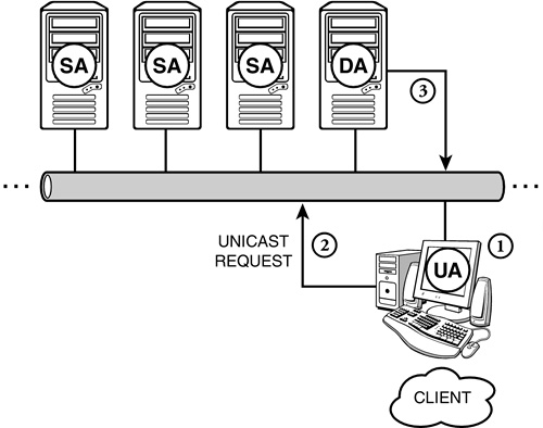
In this section, we discovered a lot about name service providers, SLPv2 architecture, and communications with and without directory agents. Now we’ll venture off the easy path into a much more sophisticated configuration lesson. Next, you’ll learn how to configure SLPv2 DAs, SAs, and UAs with NetWare 6’s new and exciting Web management tool—iManager. And while you’re at it, don’t forget our new NetWare 6 motto: “iManage, therefore I am.”
Although SLPv2 employs a sophisticated and complex architecture, its configuration in NetWare 6 is quite simple. Before we get into the nuts and bolts of actually configuring SLPv2, however, let’s look at some design considerations.
By default, NetWare 6 enables SLP in a small network configuration. As shown in Figure 6.16, the default SLP configuration does not include directory agents. Instead, it relies on distributed service agents to respond to UA service location queries.
The small network design is the default configuration for a newly installed NetWare 6 network. After a typical NetWare 6 installation on the server and workstations, SAs and UAs join the SLP multicast group at IP address 224.0.1.22. When a service starts at a network boot, it registers itself with the SA running on that server. The SA knows about only services running on its server.
When deciding where to place SLP scope objects in the eDirectory tree of a small network, keep in mind that you’ll most likely only have one object. The most logical location would be next to the Server object. However, if you expect your network to grow significantly over a short period of time, placing the object at the top of the tree would probably be a good choice.
A medium network is classified as one that has more than 25 servers but does not incorporate a WAN. Because multicasts generated by client UAs can be quite excessive in these networks, you should consider using DAs, SAs, and UAs. When started on the network, the SAs and UAs send a DA discovery packet to the 224.0.1.35 multicast group (a very exclusive group that only DAs belong to). This process is known as active discovery. DAs then become the central reference point for all services available on the network because they respond to all service requests, registered or not.
You have three options to providing UAs and SAs with the DA’s IP address:
![]() Statically configure the UAs and SAs with the DA’s IP address
Statically configure the UAs and SAs with the DA’s IP address
![]() Use DHCP to distribute the DA’s IP address
Use DHCP to distribute the DA’s IP address
![]() Use messages sent by the DA over the network at regular intervals (known as heartbeat packets)
Use messages sent by the DA over the network at regular intervals (known as heartbeat packets)
You might have more than one Scope object in eDirectory for a medium network. Placing the object at the top of the tree or within a customized container would be a solid choice.
And finally, a large network is one with more than 25 servers and has one or more WAN links. This type of network uses UAs on clients, SAs on servers, and multiple DAs on specific servers. The use of multiple DAs confines SLP traffic between WAN links.
As we discussed previously, a key component to this type of network is scopes, which enable you to collect SLP information for groups of UAs, SAs, and DAs that service a geographic location on the WAN. The scopes mean that agents only communicate with other agents associated with the same scope, which keeps SLP traffic from crossing WAN links. If you have instances where one part of the WAN must access resources on a geographically separate portion of the WAN, keep the following in mind:
![]() Partition and replicate the scope containers—Novell’s implementation of SLP by default creates an organizational unit called SLP_SCOPE when a DA is first loaded on a server. This OU is placed in the same context as the server hosting the DA, and the SLP scope object is placed in the new container. You can distribute SLP information across disparate portions of the WAN by partitioning the new SLP container and placing a replica on a server at each geographic location. Each agent at each location can be configured to use all scope objects. SLP information for each site is then transferred to other locations as the partition synchronization process occurs.
Partition and replicate the scope containers—Novell’s implementation of SLP by default creates an organizational unit called SLP_SCOPE when a DA is first loaded on a server. This OU is placed in the same context as the server hosting the DA, and the SLP scope object is placed in the new container. You can distribute SLP information across disparate portions of the WAN by partitioning the new SLP container and placing a replica on a server at each geographic location. Each agent at each location can be configured to use all scope objects. SLP information for each site is then transferred to other locations as the partition synchronization process occurs.
![]() Statically configure each DA to replicate data with each other—By editing each DA’s SLP.CFG file to specify other DA’s to communicate with, clients at each location still communicate only with their local DA. However, each DA has the services of the other DAs that are registered.
Statically configure each DA to replicate data with each other—By editing each DA’s SLP.CFG file to specify other DA’s to communicate with, clients at each location still communicate only with their local DA. However, each DA has the services of the other DAs that are registered.
![]() Statically configure the UAs at each site with the IP address of their local DA and the IP address of the remote DA—UAs communicate directly with the remote DAs to locate remote services. This is the least favorable option because unicast SLP traffic will cross WAN links.
Statically configure the UAs at each site with the IP address of their local DA and the IP address of the remote DA—UAs communicate directly with the remote DAs to locate remote services. This is the least favorable option because unicast SLP traffic will cross WAN links.
Because large networks use multiple scope objects in eDirectory, the most logical place to put them would be at the top of the tree that does not cross a WAN link, or even in a customized container. However, because you might have multiple administrators in a large network, placing the object next to the Server object might provide easier administration.
If you’re installing NetWare 6 in a large network, you might consider manually configuring SLPv2 on the following three components:
![]() SLP DA Configuration
SLP DA Configuration
![]() SLP Client Configuration
SLP Client Configuration
![]() SLP Server Configuration
SLP Server Configuration
In a medium- to large-sized network, SLP directory agents provide scaling and remote WAN support. When you configure SLP, all SLP eDirectory objects are created in the same container as the host server. This is fine for small- or medium-sized networks, but it causes significant remote traffic delays across WAN links in large networks. As a result, you should consider creating local DAs within each remote site.
In this instance, each remote DA should host its own SLP scope so that local UAs use it for service discovery. In ACME, for example, we’ll create a unique directory agent and SLP scope for each geographically separated Organizational object, including NORAD, Sydney, Tokyo, Rio, and Camelot.
Follow these short steps to configure one or more SLP DAs on your network:
1. Type SLPDA at the NetWare 6 server console and press Enter.
2. When prompted, continue with the default configuration by selecting Yes. At this point, NetWare 6 creates an SLP scope container and the all-encompassing DEFAULT scope.
3. To customize multiple scope names, simply navigate to the appropriate scope object in ConsoleOne and choose Rename. Give each scope a unique and descriptive name and click OK to finish the process. Then you’ll have to configure the DA with the name and context of the scope object.
After your directory agents have been enabled, it’s time to configure user agents to access them.
The goal of SLP client configuration is to point each of your client’s UAs to the appropriate DA for service requests. This step is trivial (and unnecessary) if you have only one DA on the network because all clients point at the default DA. However, if you have enabled multiple DAs on the network, you must tell each client where to go for network services.
You can configure Novell clients for SLP in one of two ways:
![]() SLP static client configuration—Within the Novell Client Properties dialog box of Windows 95/98/2000/XP
SLP static client configuration—Within the Novell Client Properties dialog box of Windows 95/98/2000/XP
![]() SLP dynamic client configuration—By using DHCP Services
SLP dynamic client configuration—By using DHCP Services
The Novell Client Properties dialog box within Windows 95/98/2000/XP includes a Service Location tab for manually configuring SLP client data. Follow along with Figure 6.18 as we manually configure these three options:
![]() Scope List—Scopes in this field force the UA to communicate only with DAs and SAs within the same scope.
Scope List—Scopes in this field force the UA to communicate only with DAs and SAs within the same scope.
![]() Static—If you check the Static box within the Scope List frame (shown in Figure 6.18), the UA only uses scope names in the scope list. If this box isn’t marked, the UA uses statically configured scopes and any scopes it discovers on its own.
Static—If you check the Static box within the Scope List frame (shown in Figure 6.18), the UA only uses scope names in the scope list. If this box isn’t marked, the UA uses statically configured scopes and any scopes it discovers on its own.
![]() Directory Agent List—This option enables you to precisely identify the Directory Agent IP address or DNS name you want the client UA to use.
Directory Agent List—This option enables you to precisely identify the Directory Agent IP address or DNS name you want the client UA to use.

As you learned earlier, DHCP enables us to pass a variety of TCP/IP client configuration data to each network workstation. In this case, we can use it to deliver SLP parameters. Follow along with Figure 6.19 as we use DHCP to dynamically pass SLP configurations to Novell clients:
1. Activate the DNS/DHCP Management Console from your administrative workstation and select the DHCP Services tab.
2. Next, select a Subnet object and choose the Other DHCP Options tab.
3. Create a DA option containing the IP address of this client’s DA and the name of its Scope object. Click OK to save the changes and to exit DNS/DHCP Management Console.
4. Unload and reload DHCPSRVR.NLM at the server console to enable the new changes.
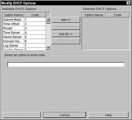
After you’ve completed the SLP client configuration, there’s only one component left: the SLP server.
Just as you statically configure which DA and scope a client uses, you can configure which DA and scope each server uses. This enables you to limit the amount of SLP traffic on your network by creating a DA/scope hierarchy.
In ACME, for example, we want each of the NORAD servers to access the NORAD DA within the NORAD scope for service location data.
To configure NetWare 6 servers to use specific SLP DAs and scopes, use these two commands at the server console:
![]() SLP Server DA—To configure a server to point to a specific DA, enter the following command at the bottom of these servers’ SYS:ETCSLP.CFG configuration file:
SLP Server DA—To configure a server to point to a specific DA, enter the following command at the bottom of these servers’ SYS:ETCSLP.CFG configuration file:
DA {network protocol},{DA IP address}
Then restart your server for the changes to take effect.
![]() SLP Server Scope Configuration—To configure a server to operate within a specific SLP scope, enter the following SET command at the server console:
SLP Server Scope Configuration—To configure a server to operate within a specific SLP scope, enter the following SET command at the server console:
SET SLP SCOPE LIST={scope name}
Then restart your server for the changes to take effect.
Let’s review. So far, we’ve learned how to manage the network via NetWare 6’s cool new Web tools: Remote Manager, iMonitor, and iManager. Then we configured the pavement of the information superhighway using DNS/DHCP. In this lesson, we explored SLPv2 as an electronic GPS system for network service discovery and name resolution.
Congratulations! You’ve just helped build the foundation of ACME’s central information superhighway with the aid of scalable IP services. You’re now a bonafide NetWare 6 DNS/DHCP engineer.
So, what’s next? Now that you’ve completed the IP framework of Novell’s Internet, it’s time to begin populating it with 21st century resources and applications—aka Internet infrastructure. To be truly successful in cyberspace, you need to become a Webmaster, too.
A noble proposition!