Figure 10.12 The ‘View’ toolbar

See also “Viewing Diagrams” later in this chapter.
Changing Focus
There are several ways to focus your attention on a given view. Usually, you will change focus by clicking on a tab or view title, but you don’t have to do that. On the Window menu, the Windows option allows you to select any of the currently available views, or any of the currently-open diagrams. The selection is shown in Figure 10.13.
Figure 10.13 A list of windows

The list of open diagrams is also available on the Canvas tool bar, as shown in Figure 10.14.
Figure 10.14 Canvas toolbar

Re-arranging the Canvas
The Canvas is a special view that displays diagrams as tabbed documents. You can drag other views onto the Canvas, but you cannot drag Canvas diagrams elsewhere in the PowerDesigner window (though you can promote them to independent windows). Right-click a diagram tab to access a contextual menu that lets you close the diagram, close every diagram except this one, or split the canvas horizontally or vertically.
By default, the canvas is a single pane with a tab for each diagram that is currently open. When you open a new diagram, it opens in a new tab in the same pane. By default, all the diagrams you open will be within the same pane, and you will only see one diagram at a time,
I often want to have several diagrams visible at the same time, and PowerDesigner allows you to do just that. All you have to remember is that you can drag and dock a diagram tab in the same way as any other view, or leave them floating in independent windows. The caveat is that diagram tabs can only dock within the canvas, not in the Browser, Toolbox, or anywhere else.
When you drag a diagram tab, the four-way dock selector appears in the Canvas; hover over one of the selectors, and the potential position of the diagram is highlighted for you. In Figure 10.15, the diagram 0:Main has been dragged onto the bottom selector.
Figure 10.15 Dragging a diagram

 You can have more than one view of the same diagram. In Figure 10.16, there is one tab for the diagram Chapter 7 CDM and two tabs containing different views of the diagram Figure 14.2. Any changes you make to Figure 14.2 will affect both tabs. To open a second or subsequent tab for a diagram, click the existing tab for that diagram, and then select New Window on the Window menu. The new tab may appear in the same pane as the existing tab, so you may need to drag one of them to another area of the canvas.
Figure 10.16 Two views of a diagram

Working with Objects
Remember that an object is a ‘thing’ in a model. Entities, attributes, relationships, data items, domains etc, are all objects. You can examine and edit the properties of objects in several ways:
· Object property sheets, which permit you to view and edit the properties of objects in your models. You can access an object's property sheet by double-clicking its symbol or Browser entry, or right-clicking it and selecting Properties. In the section ‘Many Ways of Doing Things’, we present some of the other ways of accessing an object property sheet. Figure 10.17 shows a typical object property sheet. See “Object Property Sheets”, later in this chapter, for more information.
Figure 10.17 A typical object property sheet

· Object lists - provide a spreadsheet-like presentation of, and allow for the easy creation and modification of one or more objects in your model. Lists are available under the Model menu, and on the property sheets of composite objects such as entities, tables, and classes, which contain sub-objects. Figure 10.18 shows a typical list. This list has been configured to show additional properties that the default list did not display. The tools in the Toolbar allow you to create or add, copy, or delete objects in the list, and open their property sheets. You can Ctrl-click to select multiple objects in the list and then edit their properties simultaneously. Other tools allow you to control the columns displayed in the list and to sort or filter the list. You can also print the contents of the list, and export the list to a spreadsheet or CSV[3] file. See “Object Lists”, later in this chapter, for more information.
Figure 10.18 Typical object list

Looking at the Demo Workspace
Nothing reinforces learning better than doing the work yourself, so now it’s time to start PowerDesigner. If you haven’t installed it yet, you can download the evaluation version from www.sybase.com/powerdesigner. You will be able to use all of PowerDesigner’s features for 15 days.
YOUR TURN TO PLAY
1. Start PowerDesigner, and then open the demo workspace supplied by Sybase. Click on the File menu, followed by ‘Open Workspace’; the demo workspace is called ‘demo.sws’; you can find it in the folder ‘C:Program FilesSybasePowerDesigner 16Examples’. If you’ve installed PowerDesigner on a 64-bit system, choose the folder ‘Program Files (x86)’.
The demo workspace contains a number of folders and models, and is a good place to play with PowerDesigner safely. Figure 10.19 shows the contents of the workspace.
Figure 10.19 The Demo Workspace
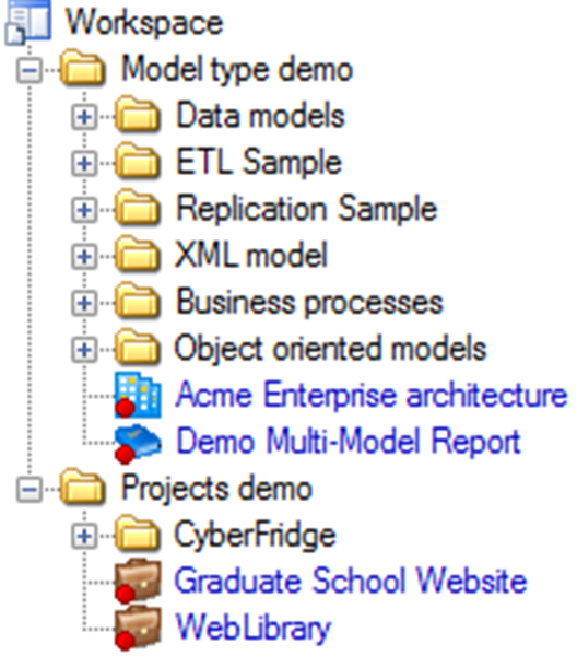
You can see that the workspace contains a mixture of folders, models, and projects. Folder names are shown in black, project and model names are shown in blue. The briefcase icon ![]() represents a project, which is a collection of folders, models, and other files. You’ll find out more about workspaces, models, and projects later in this chapter.
represents a project, which is a collection of folders, models, and other files. You’ll find out more about workspaces, models, and projects later in this chapter.
Take note of the icons in front of each model name - the icon identifies the type of model. The same icons are used elsewhere in the book.
2. Now open the ‘Data models’ folder, and double-click the model called ‘Project Management (CDM)’. PowerDesigner opens the model in the Browser, and also opens the default diagram on the Canvas, as shown in Figure 10.20.
Figure 10.20 The Project Management CDM

3. It’s possible that PowerDesigner will tell you that you can only open the model read-only, because it’s stored in the Program Files folder. That’s not a problem for what we’re looking at here, but you may wish to move the demo workspace to another folder. Here is what you need to do:
a. Move or copy the whole ‘Examples’ folder to another folder where you have update rights. Let’s call this folder ‘XX’
b. In PowerDesigner, click on Tools|General Options.
c. Select the <Named Paths> category, and then amend the entry for <_EXAMPLES_> to provide the full path to folder ‘XX’
d. Open the Demo workspace in the new folder
In Figure 10.20, the Toolbox has been populated with buttons, some of which are specific to this type of diagram. The Output window is open; you can close it by clicking <X> in the window’s title bar, or you can right-click the title bar, and select auto-hide. You can close the Browser and Toolbox in the same way.
The Toolbox
 Figure 10.21 shows the Toolbox for a CDM, which contains four categories of tools. Each type of diagram has its own specific category - the ‘Conceptual Diagram’ category is specific to the current diagram.
Free Symbols and Predefined Symbols do not have an underlying object definition, they are purely graphical. We’ll see how to make use of these later in this chapter – look for “Communicating Your Message”.
Figure 10.21 Conceptual data model Toolbox

The Standard tools allow you to do things with symbols on a diagram; the remaining tools allow you to create or select objects on diagrams.
To create an object, click the appropriate tool, and then click in the diagram. When you release the mouse button, the object is created, and you can click again elsewhere to create a second object of the same type. To release the tool, simply select another tool or right-click in free space. To revert to a previously selected tool, hold down <Ctrl> and perform a double right-click.
To create a link, click the appropriate link tool, click in the object from which you want the link to begin and hold the mouse button as you drag the pointer to the object in which you want the link to end. When you release the mouse button, the link is created. The link tools are circled in Figure 10.21.
You will find out more about creating link objects in Chapter 13 – look for “Creating a Relationship from the Palette”.
You can also use the Toolbox to select all symbols of a given type in the current diagram. For example, double-clicking the ‘entity’ tool will select all ‘entity’ symbols. To add another type of symbol to the selection, just hold down the <Shift> key and double-click another tool, such as ‘relationship’. The standard tools are shown in Table 10.2.
Table 10.2 Standard tools
Icon | Icon Action |
|---|---|
| Pointer [default] – Selects, moves, and resizes individual symbols. Double-click to select all the objects in the diagram. To switch back to the Pointer from another tool, right-click anywhere in the diagram. |
| Grabber – allows you to select, move and resize the entire diagram. Double-click to display the entire diagram, centered. |
| Zoom in |
| Zoom out |
| Open the diagram of a composite object or packages |
| Open the property sheet of an object |
| Delete a symbol and, optionally, its associated object. |


We’ll look at some of the diagram-specific tools later. Note that the availability of some tools may depend on your model options. For example, two of the tools in Figure 10.21 are unavailable because the model notation does not include support for ‘Merise’. The standard free symbols are shown in Table 10.3.
Table 10.3 Free symbols
Icon | Icon Action | Example |
|---|---|---|
| Insert a symbol that can contain text – this can be linked to other symbols (below). The standard RTF editor can be used. |
|
| Draw one of the following: There are three points on the link for labels – double-click the line to edit text. The standard RTF editor can be used. The style of the corners can be changed – right-click the line and select Format from the contextual menu. |
|
| Insert a title box – displays information such as: · the model and the package to which the diagram belongs · the name of the diagram itself · the author and version of the model · the date of modification. If no Author is specified in the model property sheet, the user name specified in the Version Info page is used. You can choose to display the repository version number of the model or a user-defined version number on the Title display preferences page. Double-click the title box to open the property sheet for the model. |
|
| Insert free-standing text, without a symbol outline – you can insert free text in your model independently of any shape, and can select and move it like any symbol. Click once to create the text symbol, then double-click it to edit the text. |
|
| Draw a line between two points – depending on your display preferences, this line may have corners. This line cannot have any associated text. |
|
| Draw an arc between two points – this line cannot have any associated text. |
|
| Draw a rectangle by dragging the mouse, release the mouse button to complete - press <Ctrl> while drawing to create a square. Double-click the symbol to edit text - the standard RTF editor can be used. |
|
| Draw an ellipse by dragging the mouse, and release the mouse button to finish - press <Ctrl> while drawing to create a circle. Double-click the symbol to edit text - the standard RTF editor can be used. |
|
| Draw a rounded rectangle by dragging the mouse, release the mouse button to complete - press <Ctrl> while drawing to create a rounded square. Double-click the symbol to edit text - the standard RTF editor can be used. |
|
| Draw a jagged line (polyline) by dragging the mouse - release the mouse button at each point where you want to create a corner. Right-click to finish. There are three points on the link for labels – double-click the line to edit text. The standard RTF editor can be used. The style of the corners can be changed – right-click the line and select Format from the contextual menu. |
|
| Draw a polygon by dragging the mouse - release the mouse button at each point where you want to create a corner. Right-click to finish and close the polygon. The style of corners will depend on your display preferences. The polygon cannot have any associated text – if you need to include text, follow these steps: 1. use the 2. use the Order options on the symbol contextual menu to bring the text in front of the polygon 3. select both the polygon and text symbols 4. select the Group Symbols option on the contextual menu (or on the Symbol menu) – the two symbols are combined into a single symbol. 5. To edit the text, ungroup the symbols first. | Original symbol
Grouped with free-standing text
|


| “Creating Objects from the Toolbox” (Core Features Guide) |

If the Toolbox is not visible, it must have been hidden or closed. If it’s closed, open it via the ‘View’ menu. If it’s hidden, the Toolbox tab will be visible, probably on the right-hand side of the screen. Hover your mouse over the word ‘Toolbox’, and it’ll appear.
Working in the Browser
The Browser displays hierarchical views of the contents of a local workspace, the glossary, and the repository, using three tabs called, unsurprisingly, Local, Glossary, and Repository. The best way to learn about the contents of these tabs is to use them, so we’ll start with the ‘Local’ tab.
YOUR TURN TO PLAY
Expand the contents of the data model in the Browser, by clicking on the ‘+’ to the left of the model name. The model contains three diagrams, and instances of the following types of object: Business Rule, Domain, Entity, Relationship, Inheritance, and Data Format. Later in the book we’ll find out what these things are. For now, expand the list of entities by clicking on the ‘+’ to the left of the word ‘Entities’, expanding the first entity, and then expanding the list of attributes that is displayed. Figure 10.22 shows the content of the model in the Browser.
Figure 10.22 The expanded model
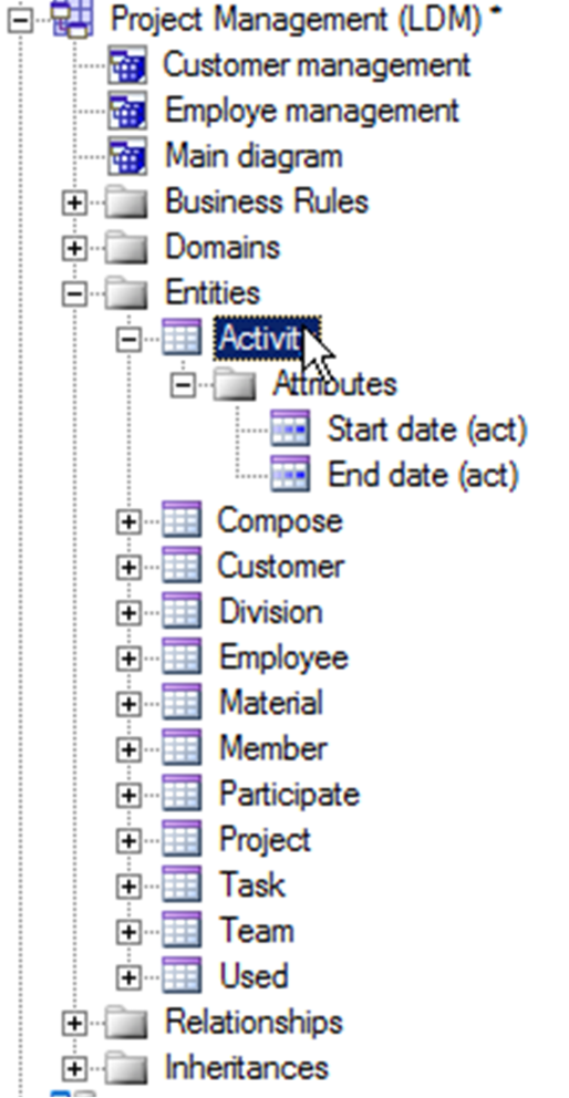
This Logical Data Model has three diagrams, shown immediately below the name of the model. The diagram called ‘Main diagram’ is the default diagram; this is the diagram that was automatically opened when you opened the model.
 It is worth mentioning here that the name of the model and the name of the file it is contained in do not have to be the same. You can change the model name as many times as you like, and it’ll still have the same file name.
YOUR TURN TO PLAY
1. In Figure 10.22 we expanded the list of attributes for the Activity entity; you’ll see that it has two attributes. These are listed inside the entity because they’re sub-objects. They cannot exist in their own right, they only have meaning in the context of the entity.
2. Now, right-click the name of the Activity entity in the Browser, and you’ll see a contextual menu appear, shown in Figure 10.23.
Figure 10.23 Contextual menu for an entity object in the Browser
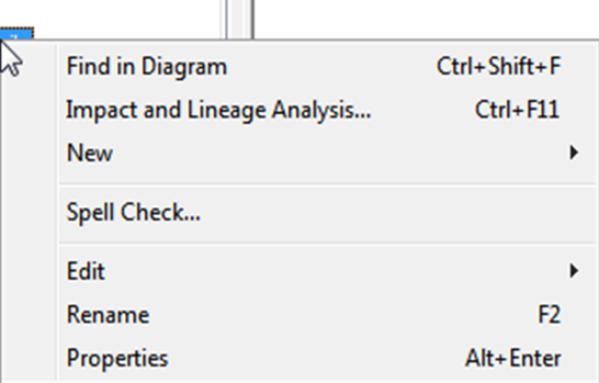
3. This is a good representation of the common options available on contextual menus, though these menus do differ slightly depending on the type of object. Now click on ‘Properties’, and you’ll open the object property sheet for the entity. You can also open it by double-clicking the entity name in the Browser.
![]() “The Browser” (Custom Features Guide)
“The Browser” (Custom Features Guide)
Contextual Menus
If you right-click any symbol or reference to an object in PowerDesigner, a contextual menu will appear. References to objects can be found in the Browser, a list of objects, a list report, or a list of search results (called a result list – see “Object Lists” later in this chapter.
Figure 10.24 shows the contextual menu displayed when you right-click an entity symbol on a diagram. Notice the similarities between this and Figure 10.23, at the top and bottom of the menu. The entries from ‘Related Diagram’ down to ‘Order’ only apply to symbols – we’ll come across all of these later.
The Browser menu shown in Figure 10.23 doesn’t include access to the Entity’s ‘Attributes’ and ‘Identifiers’. These are easily accessible in the Browser, by expanding the entity node, as shown in Figure 10.22.
Figure 10.24 Contextual menu for an entity symbol

Object Property Sheets
Figure 10.25 shows the object property sheets for four entities, with each one displaying a different tab. All four sheets are open at the same time. Don’t worry about the detail of each sheet just yet – we’ll look at these later.
For the ‘Compose’ entity, we can see the ‘General’ Tab. Every object has one of these, which, by default, shows the object name, code, and a comment. The comment is where you may include a more descriptive name for the object. By default, the comment is one of the standard properties of an object that you can display on a diagram, but it would be better for most types of object to show the description, which is on the ‘Notes’ tab. Later we will show how to display the description on a diagram.
When you make changes to an object via the object property sheet, the changes are not applied until you click <OK> or <Apply>. Before pressing either of these buttons, you can prevent changes from being applied by clicking on <Cancel> or pressing <Esc>. If you want changes to be applied as soon as you make them, you can enable the ‘auto commit’ option in <General Options> (see Figure 11.4 in Chapter 11).
From this point on, we’ll shorten ‘Object Property Sheet’ to ‘Property Sheet’ where it makes sense to do so without causing confusion.
Figure 10.25 Example object property sheets

Hover the mouse over the edges of the property sheet, and you can use the standard Windows functions to stretch or shrink it to suit. You also have a ‘Maximize’ button in the top right corner, so you can make it fill the screen. Look out for these features on other PowerDesigner windows, such as when generating or comparing models.
![]() “Selecting, Editing and Resizing Symbols” (Core Features Guide)
“Selecting, Editing and Resizing Symbols” (Core Features Guide)
| You can stretch or shrink a property sheet. You can even hit the ‘Maximize’ button so that it fills the screen. This also applies to some other PowerDesigner features, so look out for the ‘Maximize’ button; it’s really useful on List reports and Dependency Matrices. |

The content of the ‘Attributes’ and ‘Identifiers’ tabs in Figure 10.25 look very similar, because they both show a list of sub-objects, and the lists both show the default set of properties. The toolbars are almost identical.
Property Types
Object Property Sheets organize the properties of an object using tabs. Some tabs contain multiple properties, others contain only one property – this is more likely if the property is a Collection. Some tabs (such as Traceability Links) organize their content with sub-tabs.
PowerDesigner provides two types of properties – Attributes and Collections. See Table 10.4.
Table 10.4 Property types
Attribute* | Any property with a single value, such as ‘Comment’, ‘Name’, ‘Stereotype’, ‘Data Type’ and ‘Description’. |
Collection | A group of sub-objects such as ‘Attributes’, or other objects, such as the diagrams an entity appears in. When you add a Collection, you are able to limit the number of entries shown in the symbol, and also select the sub-object properties that can be displayed. |
* In Table 10.4, the word ‘Attribute’ does not refer to an attribute on an entity (see Chapter 4). It refers to a type of property on a PowerDesigner object.
More Tabs for an Entity
YOUR TURN TO PLAY
- In the property sheet for the ‘Employee’ entity, click on the ‘Attributes’ tab, double-click on the number to the left of any of the attribute names, and the property sheet for that attribute will open. Notice how different this is from the sheet for the entity. Now close the attribute property sheet. The simplest way to do this is to press <Esc> or click on <Cancel>.
- On the entity property sheet, click on the button labeled ‘More >>’; the number of tabs has increased, as shown in Figure 10.26.
The four tabs that were originally displayed are called your ‘Favorite’ tabs, and you can choose which ones to show via the menu option ‘Customize Favorite Tabs’ at the bottom of the property sheet. The menu also allows you to navigate to any of the symbols for the object on diagrams, or find the object in the Browser.
Figure 10.26 shows the ‘Version’ tab for an entity, which provides audit information, and also tells you which object this entity was generated from; let’s call this the source entity. If you click on the (circled) tool to the right of the object name, you can open the property sheet for the source entity, even though it’s in a different model and, therefore, in a different file. Now close the entity property sheet, it’s time to see some more menus.
 An object has only one definition, no matter how many diagrams it appears on. You can change the appearance and content of symbols on diagrams, so that they look very different, but they will still refer to the same underlying definition.
YOUR TURN TO PLAY
Right-click the name of the Activity entity in the Browser, and select Find in Diagram: PowerDesigner immediately focuses on the symbol in the ‘Main diagram’ and selects it. Now do the same for the Employee entity. This time a selection list appears, because the entity is included in more than one diagram. The selection list is shown in Figure 10.27.
Figure 10.26 More tabs for an entity
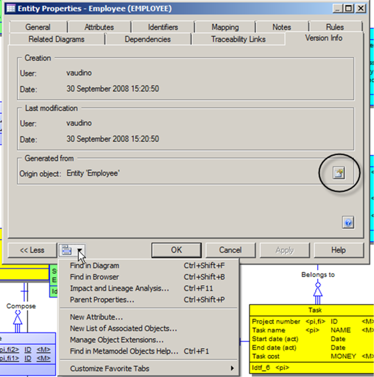
Figure 10.27 Choose your symbol

To go to a symbol, select one of the entries in the list and click on <OK>, or double-click one of the entries.
PowerDesigner allows you to include an object more than once on a given diagram, the symbols are known as Graphical Synonyms. If your object has graphical synonyms, you’ll see more than one entry in the list for a given diagram. Don’t worry if you choose the wrong graphical synonym. You can easily find the other graphical synonyms once you have the diagram in front of you. We will show you how later in this chapter.
Common Properties
As you open more property sheets, you’ll see a pattern emerging - there is a standard set of properties common to all PowerDesigner objects. We have already discussed the name and code; the remaining properties are shown in Table 10.5, listed in the order in which you’re likely to see them in a property sheet.
The Glossary Term is an exception – text in the ‘comment’ property of a Term can be displayed when the Glossary suggests terms for use in object names. See “The PowerDesigner Glossary” in Chapter 12. |

![]() “Object Properties” (Common Features Guide)
“Object Properties” (Common Features Guide)
![]() “Stereotypes (Profile)” (Customizing and Extending PowerDesigner)
“Stereotypes (Profile)” (Customizing and Extending PowerDesigner)
Do not generate me
The Generate property is common across most objects in PowerDesigner. You will find it on the ‘General’ tab of a property sheet, with a default value of ‘True’. If an object has this property set to ‘False’, it will not be included in any generated models.
Table 10.5 Common properties
Tab Name[4] | Property | Description |
General | Comment | A textual description of the object (see note below). |
General | Stereotype | Keywords that can be used to classify an object. Can be used as a simple label on a symbol, or provide a means of extending and altering the standard behavior of PowerDesigner. You can enter a stereotype directly in this field, or add stereotypes to the list by specifying them as a model extension. |
General | Keywords | Provide a way of loosely grouping objects through tagging. Separate multiple keywords with commas. You can use keywords as criteria for finding objects, and in impact and lineage analysis. |
Notes | Description | A textual description of the object. The property can be edited directly in the tab with the internal PowerDesigner RTF editor. |
Notes | Annotation | Notes regarding the implementation of a model or the objects it contains. For example, an annotation of the Employee entity might read: “Verify list of attributes with Director of Human Resources.” The property can be edited directly in the tab with the internal PowerDesigner RTF editor. |
Rules | Rules | Lists the business rules associated with the object. A business rule may be a government-imposed law, a customer requirement, or an internal guideline. |
Requirements | Requirements | Lists the requirements that the object is intended to satisfy. |
Related Diagrams | Related Diagrams | Diagrams that provide additional information about an object. You can associate any type of diagram open in the workspace with an object. |
Dependencies | Dependencies | Links to other objects in the same model, or other objects managed by PowerDesigner. |
Traceability Links | Traceability Links | User-defined documentary links between objects. Links can be stereotyped and classified by user-defined link types. |
Version Info | Creation Information | The date and time that the object was created and the name of the user who created it. Provides details about the object owner, creation and modification dates, and allows you to access help for the PowerDesigner metamodel metaclass on which the object is based. |
Version Info | Modification Information | The date and time that the object was last modified and the name of the user who modified it. |
Version Info | Generated From | Information about the object that this object was generated from. Details are only available if the source model is open. The model can be opened by clicking on the ‘Properties’ button to the right of the object details. |
Many Ways of Doing Things
PowerDesigner provides you with many ways to access the functionality provided. Here’s a quick list.
· Options on the Main Menu at the top of the interface
· Contextual menus, obtained by clicking the right mouse button
o On any symbol in a diagram
o On a blank area of the diagram Canvas
o On any item in the Browser window
· Drag and drop between different types of windows and different models
· Drag and drop between symbols on a diagram
· Buttons on Toolbars and Toolboxes
· Buttons in property sheets
· Keyboard Shortcuts
· Double-clicking
o On any symbol in a diagram
o On any item in the Browser window.
For example, here are all the ways you can access the property sheet for a model:
· Click on ‘Model Properties’ on the Model menu (if displayed)
· Double-click a Title box on a diagram (we’ll see Title boxes later)
· Double-click the Model entry in the Browser window
· Right-click a blank area on a diagram, and then select ‘Properties’
· Open the property sheet for a diagram, and then click on the ‘Properties’ button to the right of the Parent property in the ‘General’ tab
· Select the model in the Browser, and then press <Enter> or <Alt+Enter>.
Object Lists
 Object lists provide a spreadsheet-like interface for manipulating large numbers of objects at the same time, including the ability to update multiple objects in the same way at the same time. Figure 10.28 shows a typical object list, in this case a list of entities.
Opening a List Of Objects
Lists of all the major objects in your model are available under the Model menu, or by right-clicking the name of a model in the Browser and selecting List of…. Either way, you’ll see a list of all the types of objects your model could possibly include. Each list shows all the objects of that type in the currently selected package or model, including those that do not have symbols in the current diagram. If the list is empty, then your model does not contain any of that type of object.
Figure 10.28 List of entities

Organizing a List of Objects
The properties of the listed objects are organized in columns. You can order the list using the values in a particular column by clicking on the column header. Click again to reverse the sequence. You can also filter the list according to the content of a given column – just click on the filter arrow to the right of the column name (circled in Figure 10.28). This allows you to select individual objects, and to specify conditions, such as objects created between given dates. See Figure 10.29.
Figure 10.29 Filtering an object list

 If some of your objects appear to be missing from the list, you may be showing a list of objects in a package. This happens if your current diagram is not a model-level diagram, but is a package diagram – remember what we said earlier, menus are based on the current diagram. To fix this, view the model-level diagram and re-open the list. Later in this chapter you’ll find out more about packages.
The Toolbar
Figure 10.30 shows the object list Toolbar; object lists provide a complete editing environment for objects.
Figure 10.30 Toolbar for object lists

Customizing a List of Objects
By default, an object list shows only a few properties, but you can easily change that. Just click on the Customize Columns and Filter tool in the toolbar. You’ll see a list of all the possible properties for objects in the list, as shown in Figure 10.31.
Figure 10.31 Customizing a list

The columns to the right of ‘Column Heading’ allow you to specify conditions for filtering the items displayed. The arrow buttons just above ‘Show column filter buttons’ allow you to change the sequence of columns.
For now, assume we just want to change the list of properties to be displayed. We’ll uncheck ‘Code’, and then select ‘Modification Date’, ‘Parent Entity’, and ‘Has Symbol’. The result is shown in Figure 10.32.
 Short Description is a property calculated by PowerDesigner that shows a combination of the object type and name. It is not the 'Description' property.
Description Text is also a calculated property, showing a non-editable copy of the object ‘Description’.
The next time you open a list of entities in a Logical Data Model, PowerDesigner remembers your customizations, so you don’t have to.
 The same customizing and filtering options are available elsewhere in PowerDesigner – wherever you see a grid-like presentation or a list of objects or sub-objects, such as the ‘Attributes’ tab in an entity property sheet.
Figure 10.32 Modified list of entities

We can now see that two entities (Project and Task) have parent entities, and that every entity has at least one symbol on a diagram (column ‘S’).
The ‘G’ (‘Generate’) column tells you which entities would be included if you were to generate a new model from this one.
Working With a List of Objects
To select an item in an object list, click on the row number, or click directly on the property you want to change. You can select multiple individual items in a list by Ctrl-clicking them on the row number. You can also select a range of items by selecting an item at one end of the range, holding down the <Shift> key, and then selecting the item at the other end of the range.
To select all the items in a list, click the top-left corner box. When multiple items are selected, any edits you make to properties are applied to all the selected items.
Changes can be made in one row, and will be applied to all selected rows in the list.
Note: By default, you must click the <Apply> button to commit changes or the <OK> button to commit and close the list. If you prefer, you can have changes committed immediately when you enter them in a field, by enabling the ’Auto commit’ option (via the menu Tools|General Options dialog).
If you click on a blank cell in the name column, you can create a new object. However, if you close the list without applying the changes, the new objects will not be created.
Remember, you can always use the Undo tool or press <Ctrl+Z> to cancel change(s).
Creating Objects in a List of Objects
Click the ‘Add a Row’ tool  to add a new entity at the end of the list. You can also create a new entity by using the arrow keys. When you open a list, the name of the first entity is automatically highlighted for editing. Press the down arrow on your keyboard, and you select the second entry. Keep moving the arrow downwards and eventually you’ll move to empty rows, which automatically become entities.
This works in any column in the list: move down the list of modified dates, and you’ll eventually reach empty rows and start creating entities. If you have too many rows, select the rows you want to get rid of, and press <Delete>.
The new entities will not actually exist until you apply the changes via the <Apply> or <OK> buttons, or by double-clicking one of the new entities to access the property sheet. When you do this, you are asking PowerDesigner to edit an object that does not yet exist, so it will ask you to commit all the changes you have just made, first. That means ALL the changes, not just the entity you double-clicked. See Figure 10.33.
Figure 10.33 Commitment required
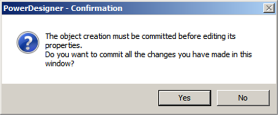
Click <Yes> to carry on, or <No> to go back to the list of objects without applying any changes.