CHAPTER 14
How do I create keys in PowerDesigner?
In Business Models
We are Identifiers
Physical keys too
In Chapter 7, we introduced Candidate Keys, Primary Keys and Foreign Keys. These are all standard data modeling artifacts that are supported by PowerDesigner. See Table 14.1.
Table 14.1 PowerDesigner support for keys
Concept | Model(s) | Object Type | Notes |
|---|---|---|---|
Candidate Key | CDM and LDM | Identifier | You can create as many identifiers as you need for an entity. |
Alternate Key | CDM and LDM | Identifier <ai> | An identifier that does not have the Primary Identifier property selected. You can create as many alternate identifiers as you need for an entity. |
PDM | Key <ak> | A key that does not have the Primary Key property selected. You can create as many alternate keys as you need for a table. | |
Primary Key | CDM and LDM | Identifier <pi> | You can only have one ‘Primary’ identifier for an entity. It is indicated via the Primary Identifier property on the ‘General’ tab on the property sheet (see Figure 14.1). |
PDM | Key <pk> | You can only have one ‘Primary’ key for a table. It is indicated via the Primary Identifier property on the ‘General’ tab on the property sheet. | |
Foreign Key | CDM | None | The CDM does not support the concept of inheritance of attributes – there are no foreign keys. |
LDM | None <fi> | Entities contain attributes migrated from other entities via inheritance links or relationships. There is no separate ‘foreign key’ object. | |
PDM | Key <fk> | Tables contain columns migrated from other tables via references. There is no separate ‘foreign key’ object. |
![]() “Identifiers (CDM/LDM)” (Data Modeling)
“Identifiers (CDM/LDM)” (Data Modeling)
![]() “Keys (PDM)” (Data Modeling)
“Keys (PDM)” (Data Modeling)
Creating Candidate Identifiers
 There are several ways of creating identifiers in a PowerDesigner CDM or LDM. The process is essentially the same when creating keys in the PDM. In Exercise 13, you’ll have the chance to try out the options marked with
  .
.
In the Entity Property Sheet
· Open the ‘Attributes’ tab, select one or more attributes, and then click the Create Identifier tool  . The selected attributes are associated with the identifier and listed on the ‘Attributes’ tab of its property sheet. Identifiers created in this way are not Primary by default, so this is a good way to create candidate identifiers.
· Open the ‘Attributes’ tab, and check the ‘P’ column for each attribute that you want to include in the primary identifier. When you apply the changes, the identifier is created or updated.
· Open the ‘Identifiers’ tab, and click the Add a Row tool  . A new, empty, identifier will be created. You need to open the identifier’s property sheet to edit the details.
In the Browser
· Right-click the entity name; in the contextual menu select New, and then Identifier. The property sheet of the new identifier will open – see below for details.
· If an entity already has one or more identifiers, right-click the Identifiers folder below the entity name, and select New. A property sheet will open – see below for details.
In an Entity Symbol
This will only work if you have selected Identifiers in the display preferences.
Select an entity symbol, select any identifier, right-click any identifier name, and then select edit|insert; a new, empty, identifier will be created. You need to open the property sheet to edit the details.
In a Relationship Property Sheet
In the ‘Cardinalities’ tab, you can declare the relationship to be dependent. When you declare a relationship to be dependent, the migrated attributes will be included in the primary identifier of the child entity. The identifier will be created, if necessary.
Via an Excel Import
You can use the Excel Import feature to create identifiers and link them to attributes, using a similar approach to that described in “Using Excel Import to Create Surrogate Keys”, in Chapter 21.
Entity Identifier Properties
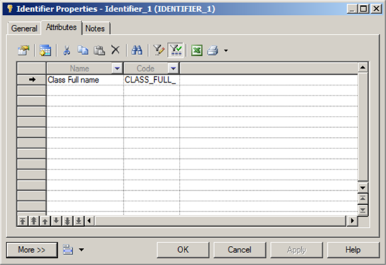
An entity identifier or a table key is a sub-object – it can only exist within an entity or table. You will generally access identifiers and keys via the ‘Identifiers’ tab on an entity property sheet, or the ‘Keys’ tab on a table property sheet. Just like other sub-objects you have seen, identifiers and keys have their own property sheets. Figure 14.1 shows a typical identifier, the primary identifier of the entity Class.
Figure 14.1 Entity identifier properties

Figure 14.2 shows the ‘Attributes’ tab of the same identifier. The identifier contains a single attribute, Class Full Name. As before, you can double-click the attribute name on the ‘Attributes’ tab to open the attribute’s property sheet.
If you want to link an identifier to the business need for it, you can link identifiers and keys to any Business Rules or Requirements that are relevant.
Object Lists
Like every other sub-object or object in PowerDesigner, you can access a grid-based object list via the Model menu. Identifiers and keys are sub-objects, so you can edit and delete them via an object list, but you cannot create them this way.
Figure 14.2 The ‘Attributes’ tab
Identifiers on Entity and Table Symbols
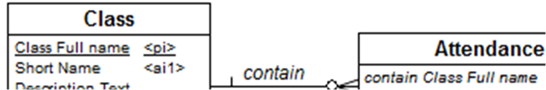
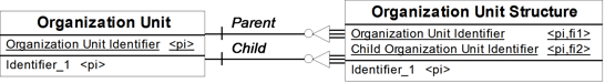
Identifiers and keys can be displayed within entity or table symbols on diagrams – just select Identifiers or Keys within Display Preferences. Figure 14.3 shows an entity and a table – the LDM entity Attendance has an identifier called Identifier_1, which contains just one attribute, Class Full Name; the entry <pi,fi1> after the attribute name tells us that the attribute is part of the primary identifier, and is also a foreign identifier, inherited via a relationship.
The PDM table Attendance has one primary key called Key_1, which contains just one column, Class Full Name; the entry <pk,fk1> after the column name tells us that the column is part of the primary key, and is also a foreign key, inherited via a dependent relationship. The entries in the bottom section of the table symbol are indexes, one for each foreign key; they are automatically created when the PDM was generated from the LDM.
Changing Identifier Content
To revise the list of attributes in an identifier, open the ‘Attributes’ tab on the identifier’s property sheet. For the primary identifier, you can change the Primary Identifier property on the identifier’s attributes, via a list of attributes (from the Model menu), the list of attributes for an entity, or an attribute’s property sheet.
Figure 14.3 Entity and table symbols
LDM Entity | PDM Table |


Identifier Migration Along Relationships
Foreign attributes are migrated instantaneously in a LDM, or during model generation when you generate a PDM from a CDM or LDM. Table 14.2 shows the rules used by PowerDesigner when migrating attributes in a LDM.
Table 14.2 Attribute migration in different types of LDM relationships
LDM Relationship type | Migration |
Dependent one-to-many | Foreign identifiers become attributes of the primary identifier of the child entity. |
Many-to-many | No attributes are migrated. |
Dominant one-to-one | Primary identifier attributes migrate from the dominant entity. |
Mandatory one-to-many | If the child to parent role is mandatory, migrated attributes are mandatory. |
 PowerDesigner allows you to choose which attributes to migrate, and which identifier to migrate them from (if you have more than one, of course).
![]() “Identifier Migration Along Relationships” (Data Modeling)
“Identifier Migration Along Relationships” (Data Modeling)
![]() “Automatic Reuse and Migration of Columns” (Data Modeling)
“Automatic Reuse and Migration of Columns” (Data Modeling)
Attribute Migration Settings
The way in which data elements migrate along relationships and references varies between the types of data model, as described in Table 14.3.
Table 14.3 Attribute migration approaches
Model Type | Migration |
CDM | No attributes are migrated, ever. |
LDM | Attributes are automatically migrated from primary identifiers into child entities. Attributes are also automatically migrated via inheritance links, and you have control over which attributes are migrated - see “Inheritance Properties” in Chapter 13. |
PDM | Columns are automatically migrated from primary keys into child tables. |
In a LDM, the Model Options shown in Figure 14.4 give you a degree of control over the migration process.
Figure 14.4 LDM Migration Settings

There are two parts to these settings. In Migrate attribute properties, you can choose whether or not the migrated attributes inherit the original attribute’s Domain, Checks, and associated Rules. By default, all the options are enabled, and you are advised to leave them as they are.
The second part controls the names of attributes migrated via a relationship. The drop down list contains templates that you can use to construct the name of the migrated attribute. For example, the template shown in Figure 14.4 will prefix the original attribute name with the role name from the ‘parent’ end of the relationship.
Figure 14.5 demonstrates the effect of the template on the ‘contain’ relationship from our model – the foreign key attribute is called contain Class Full Name.
Figure 14.5 Appending a role to an attribute name
The parent role name (contain) has been appended to the name of the original attribute to create the name of the migrated attribute, contain Class Full Name. If you intend to use this template in your models, you will probably want to ensure that your role names use initial capital letters, such as Contain instead of contain.
Several default templates are available, or you can create your own template from a combination of the options shown in Table 14.4. The template is not applied to attributes migrated through an inheritance link.
 If you manually rename a migrated attribute, future changes to the template will not affect the attribute name.
Table 14.4 Options for constructing migrated attribute names
%PARENT% | Name/Code of the parent entity |
%ATTRIBUTE% | Name/Code of the parent attribute |
Name/Code of the identifier constraint attached to the relationship | |
Name/Code of the relationship | |
Role of the entity that generated the parent entity. If no role is defined on the relationship, %PARENTROLE% takes the content of %PARENT% to avoid generating an attribute with no name |
By default, PowerDesigner will apply templates only when necessary to avoid creating duplicate attribute names in an entity. Alternatively, you can apply the template to all migrated attribute names.
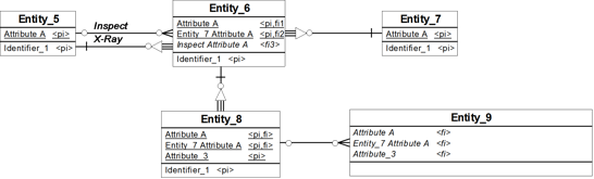
The example in Figure 14.6 shows the results of applying the same template to every migrated attribute in a different model. Without applying a template, all the attributes in Entity_6 would be called Attribute A, which we cannot allow. The relationship from Entity_7 does not have a role name, so the name of the migrated attribute is prefixed with the entity name, which will be replaced by the relationship parent role name when you define it.
Entity_8 and Entity_9 illustrate a problem with this approach – the attributes have been migrated along two or three relationships, so their names have two or three prefixes. The work-around here is to rename migrated attributes where the generated name is not suitable. Future changes to the relationship name or role name will still affect the name of the migrated attributes, so this type of amendment should be carried out at a late stage in modeling if you want to avoid rework.
Figure 14.6 Applying a naming template

Figure 14.7 shows the same model, with the naming template used when required. The X-Ray relationship was created first, so the name of the attribute migrated via that relationship does not have a prefix.
Figure 14.7 Prefix attribute names only when required
This is a contrived situation, partly showing the pitfalls of giving every attribute the same name; it’s likely that the impact on a real-life model will not be quite so onerous. Figure 14.8 shows a more realistic scenario. The Parent relationship was the first to be created, which explains why it is the attribute inherited from the Child relationship that has the qualified name.
Figure 14.8 A more realistic scenario
The default template in PowerDesigner is “%.3:PARENT%_%ATTRIBUTE%”. This prefixes the attribute name with first three characters of the entity name followed by an underscore, which will result in attribute names such as “Cla_Class Full Name”.
Changing the Migration Settings for a model will affect the model immediately, and could potentially rename all of the migrated attributes.
![]() “Migration Settings (LDM)” (Data Modeling)
“Migration Settings (LDM)” (Data Modeling)
Migrating a Different Identifier
PowerDesigner allows you to select any of the keys of a parent entity to form the foreign key in a child entity. For example, you could choose to propagate the attributes from an alternate key, rather than the primary key. A join is a link between an attribute in a parent entity and an attribute in a child entity (attribute pair), defined within a relationship. Using the ‘Joins’ tab in the relationship property sheet (see Figure 14.9), you can choose which key to use in the join, and which attributes in the child entity form the foreign key.
Figure 14.9 Choosing a different identifier to join with

This flexibility can cause you potential problems when, for example, you create surrogate identifiers in an existing model, and convert the original primary identifiers into alternate identifiers.
 This feature is also available for references in the PDM.
If you convert an existing primary identifier into an alternate identifier, the alternate identifier will continue to be used in the join, and the attributes in the alternate identifier will continue to be propagated as foreign identifiers. If you then create a new surrogate identifier attribute, and make that your primary identifier, PowerDesigner will not change the relationship joins for you.
To prevent this from happening, always create the new primary identifier attribute first, and mark it as Primary. Only then should you create your new alternate identifier. It is OK if you do all this in the same editing session, it’s the sequence of events that counts.