
Chapter 7. Integration architecture with Mule
- Structuring integration applications
- Common architectures used in Mule applications
- Mule application implementation patterns
During the course of this book, we’ve shown you the building blocks of piecing together integration solutions with Mule. We haven’t, however, talked about the architecture of such applications. Ideally your Mule applications should exhibit the properties of any other well-architected software application: they should be easy to refactor and test, modular, and decoupled. They should also be constructed with a view to future needs, making them easy to modify as requirements inevitably change.
In this chapter, you’ll see how to architect integration solutions with Mule. We’ll start off by presenting three different architectural approaches to structuring Mule applications. We’ll then take a look at implementation patterns that can aid in the composition of integration solutions. Seeing how Prancing Donkey approaches and evolves their integration solutions will glue together the concepts we introduce.
Hopefully you’ll finish this chapter by getting the big picture of how real-world applications are composed using the techniques in this book.
7.1. Structuring integration applications
Mule can function in multiple ways, from an integration application to the central integration fabric of a Fortune 500 enterprise. The architecture of these applications, whether implicit or explicit, will impact their success. In this section, we’ll look at three ways Mule can be used for nontrivial projects.
7.1.1. Guerrilla SOA with hub and spoke
Integration is, by its nature, often ad hoc. All developers wish for unbounded time constraints and an unlimited budget to realize a platonic ideal of architecture, implementation, and delivery. The reality, particularly with integration products trying to realize the cost benefits associated with SaaS solutions, is often the opposite.
A core benefit of integration frameworks such as Mule is that they provide structure around these integration exercises, avoiding the dreaded plate-of-spaghetti, point-to-point solutions. Ideally the integration layer should get out of the way of the developers trying to tie systems together, both when initially getting a solution up and running as well as when paying back the technical debt that has inevitably occurred.
In chapter 1 we mentioned the concept of Guerrilla SOA. This is a bottom-up approach to implementing integration architecture that values the pragmatic, iterative delivery of features over the top-down governance model of service-oriented architectures. Guerrilla SOA is best achieved using a hub-and-spoke architecture with Mule. This architecture pattern is best suited to organizations with quickly changing requirements or small-to-medium integration needs. Figure 7.1 illustrates Prancing Donkey’s current integration landscape as an example of how hub-and-spoke architectures are implemented with Mule.
Figure 7.1. Prancing Donkey’s Guerrilla SOA architecture using a hub-and-spoke architecture:  web application clients to Mule applications;
  mobile device clients to Mule applications;
  standalone Mule instance hosting four discrete applications;
  various external integration points decoupled from the front-end client.

This architecture consists of a single Mule deployment containing four Mule applications. Each application hosts services siloed based on business requirements. All the flows implementing accounting use cases, for instance, are placed in the Accounting Services application. This allows Prancing Donkey to use Mule’s hot deployment features in the standalone server to manage each application separately. It also decouples unrelated services from each other, allowing the development teams to implement integration solutions in parallel.
As in the other architecture approaches you’ll see in this chapter, Mule acts as an intermediary between all interactions with remote services. The front-end applications use the protocols that make the most sense for them to integrate with Mule. The web store, for instance, takes advantage of Prancing Donkey’s JMS infrastructure for asynchronous submission. External API clients, not being on Prancing Donkey’s network, don’t have this luxury.
Although this centralizes all the integration logic in the Mule applications, it also introduces a single point of failure. You’ll see in section 7.2 how this can be mitigated by using reliability patterns. The multitude of protocols on the front end also means that different transformation implementations are used in each Mule application, with little reuse between each application. You’ll see in the next section as well as in section 7.2.1 how the canonical domain model pattern can improve this design.
A nice aspect of hub-and-spoke architectures is that their design is typically iterative. Mule’s flexible deployment architecture, which you’ll see in chapter 8, means you can start with an embedded Mule instance in your application that’s internally decoupling integration points with the VM transport. Eventually this can be refactored into a standalone Mule application in which the services are then decoupled with JMS, a web services protocol, or something like ZeroMQ.
Teams practicing Guerrilla SOA tend to develop and own the integration solutions. This often means there aren’t developers purely focused on Mule, increasing the odds that people won’t jump through hoops to avoid interacting with a potentially slow-moving “integration team.”
Now let’s see how the ESB architecture can potentially improve on some of the deficiencies of hub-and-spoke, particularly for larger organizations.
7.1.2. Mule as the enterprise service bus
Enterprise service bus implementations are a more formal, top-down variant of the hub-and-spoke architecture. An ESB architecture is typically a piece of a larger initiative or a new “green field” development in which the team has the luxury of time and resources to plan out an integration. Usually other applications the ESB will integrate with are either known or being architected up front. In such situations a canonical domain model, which we’ll discuss in section 7.2.1, is often also known up front and is being shared with the applications integrating with the ESB. Figure 7.2 illustrates the ESB architecture of Prancing Donkey’s largest competitor, Mordor Brewing Company.
Figure 7.2. Mordor Brewing Company’s monolithic ESB architecture: SOAP is enforced as the protocol standard on all remote integration points.

At first glance, this architecture seems very similar to hub-and-spoke, and it is. The topologies are, in fact, mostly identical. In Mordor’s case, for instance, they’re still using Mule’s ability to simultaneously host multiple applications to segment their flows by business silo. The crucial difference is that this architecture was defined prior to any implementation, and that shown in figure 7.1 was drawn as a snapshot in time of the system’s evolution. The second major difference is that all traffic to and from the ESB will be SOAP over either HTTP or JMS. This limits the integration flows to purely routing, transformation, security, and possibly reliability. This makes SOAP an obvious choice as an implementation protocol, given that there are WS specifications for each of these use cases.
Because SOAP is to be strictly enforced as the communication method to and from Mule, channel adapters must be implemented for the remote integration points that don’t natively support SOAP. In this example, Mordor’s portal software has no SOAP support. As such, the portal team must implement a mechanism to bridge the portal’s internal API to speak to SOAP.
Although monolithic ESB architecture has largely fallen out of favor in recent years, it can still be a good choice for a large organization with a dedicated integration team. SOAP, despite many of its faults, still delivers excellent tooling that’s largely unrivaled by competing integration protocols such as REST.
We’ll now take a look at how Mule can function purely as a mediation layer.
7.1.3. Mule as a mediation layer
Using Mule purely for its mediation features, particularly routing and security, is emerging as a common architectural pattern. Heavily services-oriented environments introduce a unique set of problems. Multiple versions of services often need to be supported. Implementing cross-cutting concerns between services, such as security, is often a challenge. What happens, for instance, if the security infrastructure is augmented or changed in an environment with 100 back-end services? It would be nice to be able to make this change in one place rather than in 100 downstream applications. Mule’s routing and security features provide an excellent place to host this functionality.
Prancing Donkey is at the point where they want to centralize authentication and schema validation for their services. Their plan is to introduce a dedicated Mule server hosting a single application that performs mediation, as illustrated in figure 7.3.
Figure 7.3. Mule as a service mediation layer: a dedicated Mule application to perform mediation

The mediation layer will, in this case, be performing schema validation against the XML payload of the messages being passed to it. It’ll perform a security check against the messages, ensuring they have an HTTP basic authentication header that validates against Prancing Donkey’s LDAP infrastructure. It’ll then use a Java component that integrates with an external registry product to determine the final destination of the message. This is demonstrated in the flow shown in the following listing.
Listing 7.1. Using Mule as a service mediation layer

In addition to performing schema and security validation of the message, this flow determines how to route the message based
on a service registry lookup, performed by the Java component ![]() . This component populates a flow variable that populates the address of the HTTP outbound-endpoint
. This component populates a flow variable that populates the address of the HTTP outbound-endpoint ![]() .
.
You’ve seen three different ways to structure integration solutions with Mule in this section. This is obviously not an exhaustive list, but instead shows the more common architectures developers typically choose. Other architectural approaches also exist. Mule can be used, for instance, in a grid architecture with multiple nodes performing map-reduce operations on datasets, for instance. Peer-to-peer architectures are also possible.
Now let’s take a look at some patterns that simplify the implementation of these architectures.
7.2. Mule implementation patterns
In this section, we’ll take a look at patterns that simplify the composition of integration applications. These aren’t explicit features of Mule but rather are approaches that take advantage of Mule’s functionality to ease integration application development. You’ll see how adopting a canonical domain model enables you to decouple your business logic from your integration operations, such as routing and transformation. We’ll then take a look at how to use asynchronous messaging to build resiliency into your Mule flows.
7.2.1. Using a canonical data model
A canonical data model is a useful way to structure the payloads of your Mule messages to simplify the implementation of your Mule applications. To use a canonical data model, you must introduce a common format to which message payloads are transformed prior to any further processing by Mule. Canonical data models are typically Java domain objects, an XML schema, or an agreed-upon JSON format.
Let’s consider one of Prancing Donkey’s use cases. Prancing Donkey is using Salesforce as their CRM. Mule’s Salesforce connector makes the mechanics of this implementation trivial but introduces some challenges when data is retrieved from Salesforce for processing. The objects returned from the Salesforce connector are Java objects generated from the WSDL of Salesforce’s SOAP API. These objects tightly couple Prancing Donkey CRM flows in Mule to Salesforce’s API. Such a coupling will make it difficult for Prancing Donkey to change CRM providers in the future or augment the CRM functionality with another application.
A canonical data model avoids this coupling. The next listing shows the Customer domain object that’s part of the canonical model Prancing Donkey introduced.
Listing 7.2. The Customer canonical data model
@XmlRootElement
@XmlAccessorType(XmlAccessType.FIELD)
public class Customer implements Serializable {

    String customerId;
    String firstName;
    String lastName;
Now let’s look at the flows responsible for creating and querying contacts in the CRM (illustrated in figure 7.4).
Figure 7.4. Populate and query records in Salesforce

Listing 7.3. Populate and query records in Salesforce

You can see that the createContact flow uses MEL to populate the appropriate fields in the Salesforce contact object ![]() . The inverse is done using the custom transformer
. The inverse is done using the custom transformer ![]() , which converts the result from a Map to a Customer instance.
, which converts the result from a Map to a Customer instance.
The canonical data model is a great way to further decouple your Mule integrations from the rest of your applications. The example in this section used a POJO data model, but, as we already mentioned, other domain models like JSON and XML are as easily supported. The canonical data model is a powerful technique when combined with Mule’s annotation support, allowing you to keep any business logic hosted in Mule independent of Mule’s container at runtime. Such an approach makes it easy to unit test business logic code outside of the Mule container and also gives you the ability to move such code into and out of Mule as necessary.
Now let’s take a look at how you can use asynchronous messaging to reliably deliver messages with Mule.
7.2.2. Reliability patterns with asynchronous messaging
Asynchronous messaging providers such as JMS, AMQP, or Mule’s own VM transport provide an opportunity to decompose integration applications into decoupled, reliable segments. As illustrated with Gregor Hohpe’s seminal Starbucks analogy in “Your Coffee Shop Doesn’t Use Two-Phase Commit” (http://mng.bz/fb70), such approaches compose an otherwise synchronous transaction into a series of asynchronous steps. This has a variety of benefits, from allowing the client to perform other work while waiting for the “transaction” to finish to layering resiliency into an otherwise unreliable step.
Let’s consider an example. Prancing Donkey is beginning a re-architecture to allow orders to be submitted from their iPhone application. The ordering process on the server side is fairly complicated and involves multiple remote systems that Prancing Donkey has no control over (Salesforce and NetSuite, for instance). One of the goals of the re-architecture is to provide a response as soon as possible to the mobile device from which the order was submitted. This will be accomplished by accepting the order over HTTP, generating an order ID, and transactionally submitting it to a JMS queue for processing. If the JMS transaction that submits the message on the queue succeeds, then a response containing the order ID is returned to the mobile device. This ID can then be used later to track the status of the order. The “front end” part of this flow is shown in the following listing, and illustrated in figure 7.5 (transactions are covered in depth in chapter 9).
Figure 7.5. Front-end order submission

Listing 7.4. Front-end order submission
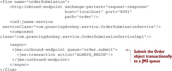
When the mobile device receives the order ID from the Mule flow, it can be sure that the order has been submitted, provided that Prancing Donkey’s JMS infrastructure is robust and the back end of the order submission is implemented properly. This ID will then be used to track the order on another screen of the mobile application’s UI. Now let’s take a look at the back end of the flow in the next listing (illustrated in figure 7.6).
Figure 7.6. Backend order processing
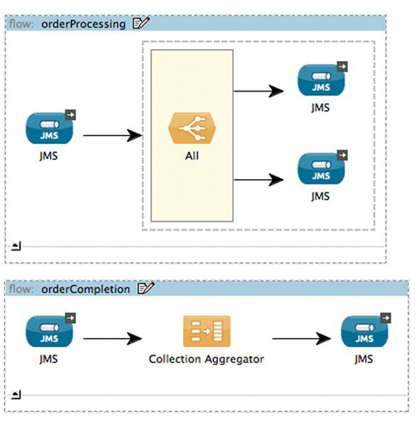
Listing 7.5. Back-end order processing

These two flows handle the asynchronous routing and aggregation of back-end order processing. The orderProcessing flow accepts a message and submits it to two queues in a single transaction. The orderProcessing flow submits the Order object to a Salesforce flow similar to the one you saw previously. The erp.order.record flow submits the Order object to a flow that uses Mule’s NetSuite cloud connector.
Prancing Donkey is using ActiveMQ’s message redelivery feature to redeliver messages up to a certain point in the event of a transactional rollback. In this case, if there’s any failure submitting to any of the queues, then the broker will attempt again after a specified interval. Once this interval is reached, the message is placed on a DLQ. This effectively makes otherwise unreliable services, such as NetSuite or Salesforce, robust.
It’s not shown in this example, but after the completion of the NetSuite and Salesforce flows, messages are sent to the order.complete queue. Mule’s collection aggregator, which you saw in chapter 5, will wait for both responses for an order to arrive before dispatching the Order on events.order.completed. Prancing Donkey uses JMS topics to generate events when certain business phenomena occur. You’ll see a little bit later how complex event processing can be used to act on this data.
Web service hosting has typically been the domain of dedicated applications or web servers like JBoss AS or Tomcat. Both platforms provide varying degrees of support for the Java EE stack and multitenancy. For web services, particularly those built on top of JAX-RS and JAX-WS, they were natural choices as host platforms. Although such applications could be hosted on Mule, this was typically a difficult affair—particularly because the standalone server could only host one application at a time, and application deploys required a restart of the server.
Things have changed in Mule 3. As you saw in chapter 3, Mule fully supports the JAXRS and JAX-WS specifications via Jersey and Apache CXF. The standalone server, as you’ll see in chapter 8, is now fully multitenant. Hot deployment of applications is also supported. Finally, Mule’s deployment descriptor, a ZIP file, is fully transparent, and those used to working within exploded WAR files will feel completely at home.
Using Mule as a decoupling middleware platform, like you saw in this section, lets you use reliable messaging to make otherwise transient, fatal errors in an unreliable transport recoverable.
7.2.3. Proxying SOAP requests with CXF
In chapter 3, you saw how JAX-WS, in conjunction with Apache CXF, can be used to build and consume SOAP web services with Mule. JAX-WS is an annotation-driven mechanism for web services consumption. It requires you to either manually define the Java classes or use an automated tool, such as CXF’s wsdl2java, to automatically generate JAX-WS classes from a WSDL.
It can be desirable, however, to avoid the overhead of intermediary Java classes and directly work with the XML payloads of SOAP requests. This would enable you to do things such as route a SOAP request based on an XPath evaluation or use XSLT to map one SOAP request to another. This can be significantly easier, and more performant, than incurring the expense of marshaling XML documents back and forth to a Java object graph.
Mule’s CXF proxy service and proxy client allow you to work directly with a SOAP message’s XML body. Let’s see how these work. You’ll start off by refactoring Prancing Donkey’s brew listing web service that you built in chapter 3 to use an external service invoked over the VM transport to get the listing of brews.
Listing 7.6. Proxying SOAP service requests with the CXF proxy

The HTTP inbound endpoint in this example is identical to the one used with the JAX-WS service class in chapter 3. You’re not changing the way you accept SOAP requests; in both cases it’s over HTTP. Things are different, however, with
![]() . The cxf:proxy-service here is performing two functions. The wsdlLocation and namespace attributes let you host the WSDL from the service without resorting to a JAX-WS annotated interface. Primarily, however,
the cxf:proxy-service is being used to strip the Envelope from the SOAP request. Listings 7.7 and 7.8 show what the SOAP request looks like before and after processing by the cxf:proxy-service.
. The cxf:proxy-service here is performing two functions. The wsdlLocation and namespace attributes let you host the WSDL from the service without resorting to a JAX-WS annotated interface. Primarily, however,
the cxf:proxy-service is being used to strip the Envelope from the SOAP request. Listings 7.7 and 7.8 show what the SOAP request looks like before and after processing by the cxf:proxy-service.
Listing 7.7. MuleMessage payload before CXF service proxy
<soapenv:Envelope
          xmlns:soapenv="http://schemas.xmlsoap.org/soap/envelope/"
          xmlns:ser="http://service.prancingdonkey.com/">
                <soapenv:Header/>
               <soapenv:Body>
                <ser:getBrews/>
               </soapenv:Body>
            </soapenv:Envelope>
Listing 7.8. MuleMessage payload after CXF service proxy
<ser:getBrews
          xmlns:ser="http://service.prancingdonkey.com/"/>
As you can see, the SOAP Envelope has been stripped from the message’s payload, allowing you to work directly with the content of the SOAP message. In this case, you’re routing the XML document minus the SOAP Envelope to a VM endpoint that’s returning the XML document shown in the next listing.
Listing 7.9. Result from vm://brew.lookup
<?xml version="1.0" encoding="UTF-8"?>
<ns1:getBrewsResponse xmlns:ns1="http://service.prancingdonkey.com/">
  <ns1:return>
     <ns2:Brew xmlns:ns2="http://model.prancingdonkey.com">
        <ns2:description>Hobbit IPA</ns2:description>
        <ns2:name>Hobbit
         IPA</ns2:name>
     </ns2:Brew>
     <ns2:Brew xmlns:ns2="http://model.prancingdonkey.com">
        <ns2:description>Frodos
         Lager</ns2:description>
        <ns2:name>Frodos Lager</ns2:name>
     </ns2:Brew>
  </ns1:return>
</ns1:getBrewsResponse>
Note that the response from the VM invocation is a plain XML document; there’s no SOAP Envelope wrapped around it. The CXF proxy service, because the flow is request-response, will wrap the message payload in a SOAP Envelope, allowing you to return a response to the SOAP client. The following listing shows what the final document looks like.
Listing 7.10. Final proxied response
<?xml version="1.0" encoding="UTF-8"?>
<soap:Envelope xmlns:soap="http://schemas.xmlsoap.org/soap/envelope/">
  <soap:Body>
     <ns1:getBrewsResponse xmlns:ns1="http://service.prancingdonkey.com/">
        <ns1:return>
           <ns2:Brew xmlns:ns2="http://model.prancingdonkey.com">
              <ns2:description>Hobbit IPA</ns2:description>
              <ns2:name>Hobbit IPA</ns2:name>
           </ns2:Brew>
           <ns2:Brew xmlns:ns2="http://model.prancingdonkey.com">
              <ns2:description>Frodos Lager</ns2:description>
              <ns2:name>Frodos Lager</ns2:name>
           </ns2:Brew>
        </ns1:return>
     </ns1:getBrewsResponse>
  </soap:Body>
</soap:Envelope>
The CXF module can also be used to proxy SOAP requests. The next listing demonstrates how you can use the CXF proxy client to wrap an arbitrary XML document in a SOAP Envelope.
Listing 7.11. Proxying SOAP client requests with the CXF proxy

The payload attribute ![]() lets CXF know if the MuleMessage is already a SOAP document. Because it isn’t in this case, you’ll set the payload to body, indicating you want the message’s payload wrapped in a SOAP Envelope. The CXF proxy client, after wrapping the message’s body in a SOAP Envelope, will send the request to the HTTP outbound endpoint. When the response comes back, the Envelope will be stripped from the message, allowing you to work directly with the XML of the response. Setting enableMuleSoapHeaders to false ensures that any outbound properties on the MuleMessage aren’t propagated in the intermediary SOAP request.
lets CXF know if the MuleMessage is already a SOAP document. Because it isn’t in this case, you’ll set the payload to body, indicating you want the message’s payload wrapped in a SOAP Envelope. The CXF proxy client, after wrapping the message’s body in a SOAP Envelope, will send the request to the HTTP outbound endpoint. When the response comes back, the Envelope will be stripped from the message, allowing you to work directly with the XML of the response. Setting enableMuleSoapHeaders to false ensures that any outbound properties on the MuleMessage aren’t propagated in the intermediary SOAP request.
Mule’s agnosticism to both the payload of message and the architecture of integration applications makes it easy to implement patterns such as the canonical data model, decoupling middleware, and generic SOAP proxies.
7.3. Summary
Defining the architecture for any software application can be a daunting task. This is particularly true of integration applications which, by nature, often involve a multitude of technologies, distributed systems, and long-running processes. In this chapter, you saw how three different approaches to integration application architecture can potentially mitigate the difficulties of such implementations. The choice of an architecture, even if it’s an evolving one, can greatly impact the agility of such applications to adapt to ever-changing requirements, technologies, and use cases. Patterns also help here. The canonical data model and the use of decoupling middleware give you additional avenues for agility.
Hopefully the discussion in this chapter will give you confidence in choosing and implementing integration applications with Mule. We’ll now take a look at how Mule applications are deployed.