

Camera Glider
Applications
Achieving fluid camera movement has bedeviled filmmakers since the first moving picture was produced. While hand-held camera shots are ideal for some situations (brief sequences or getting the “reality feel”), they often generate a wobbly recording as soon as the camera operator starts moving. Since extended shots with this type of footage can cause motion sickness in some viewers, most filmmakers do their best to avoid it.
The camera dolly is the oldest and most common method of getting a camera moving smoothly. While a dolly may be perfect for many situations, moving on uneven terrain, navigating stairs, or traveling over medium to long distances can be a problem. Even setting up the dolly track can require a substantial amount of time that you could be using to get the perfect shot!
Steady-cams were invented to solve many of these problems. A steady-cam uses a system of balances and counter-balances to soften the camera movement. Unfortunately, the cost of a steady-cam unit is outside the budget of most small filmmakers. Additionally, the complexity of the system makes it difficult to construct on your own. In contrast, the camera glider is simple to use and inexpensive to create.
The camera glider is a camera-mounting post with balancing counterweights (see figure 10-1). Essentially, the weight on the bottom of the glider dampens tilting and side-to-side motion. The arm of the operator then steadies the overall movement of the entire rig.
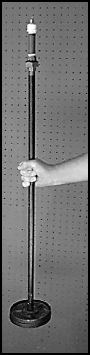
FIGURE 10.1 Camera glider with balancing counter-weights.
Mastering the camera glider can take some practice. Once you’ve learned to use it, however, you can get graceful shots that would be impossible without it. I’ve used this very glider to follow an actor through a wheat field. The footage turned out beautifully.
PARTS
| Qty | Item |
| 1 | 4″ × |
| 1 | 24″ × |
| 1 | |
| 1 | |
| 1 | |
| 1 | |
| 4 | |
| 1 | |
| 2 | 2 lb steel weights |
There are essentially two parts to the camera glider: the head and the body. You’ll mount your camera on the head while the body will hold the counter-weight. The head is connected to the body with a piece known as a “union.” As with all the parts in the camera glider, a ![]() union is available at nearly any hardware store. The advantage of employing a union between the head and the body is that it allows you to quickly and easily separate the camera from the dead weight without disassembling the whole glider.
union is available at nearly any hardware store. The advantage of employing a union between the head and the body is that it allows you to quickly and easily separate the camera from the dead weight without disassembling the whole glider.
You’ll need to select the length of pipe for the body shaft of the glider. At your local hardware store, there are typically a number of sizes of threaded iron or steel pipe available including: 12″, 24″, and 36″. Since it’s easy to swap out the body pipe, you can buy more than one length and simply use the one that best fits a given situation.
As a rule of thumb, the longer the body pipe, the steadier the camera will be. However, a longer pipe also adds more weight and makes the glider harder to maneuver. This may increase the chances that the bottom of the glider will bump into objects close to the ground, ruining your shot.
The amount of weight on the bottom should match the weight of the camera. The counter-weights balance the glider and provide the most commonly desirable shot. However, if you want footage that is not “common,” you can put a greater weight on the bottom. This unbalanced configuration creates a form of pendulum swing with the camera that can be useful for showing psychedelic or disoriented movement.
Construction
To begin construction, acquire the supplies shown in the parts list. Be sure to wash the pipes with simple soap and water and then dry them thoroughly. Pipe is often dirty when you buy it, so cleaning the material once will save you from cleaning your hands numerous times during assembly and use.
Assembling the head
Begin the assembly by putting together the head which will actually attach to the camera. Drill a ![]() hole in the top of the cap (see figure 10-2).
hole in the top of the cap (see figure 10-2).
You can use a plastic cap or a steel cap (see figure 10-3). The steel cap is highly recommended because it is stronger and therefore provides a greater safety margin. However, not everyone has the drill bits to easily go through a metal cap. I’ve used a plastic cap with cameras of various weights without any problem, but just for safety’s sake I’ve recently switched up to a steel one.
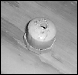
FIGURE 10.2 Drill a ![]() hole in the top of the cap.
hole in the top of the cap.

FIGURE 10.3 One plastic cap and one steel cap for the head mount.
You will need to assemble the bolt that holds the camera to the cap. Since we don’t want the camera to come loose under any circumstances, a strong “platform” is needed on both the inside and the outside of the cap. We can accomplish creating a “platform” by placing two nuts next to each other on the bolt and then tightening one down on the other. This creates a solid, largely immovable position on the bolt.
First, adjust the nuts so the bottom one is positioned about ![]() from the end as shown in figure 10-4. This length makes the bolt protrude the proper distance from the cap, so it will seat perfectly in the threaded mounting socket of your camera.
from the end as shown in figure 10-4. This length makes the bolt protrude the proper distance from the cap, so it will seat perfectly in the threaded mounting socket of your camera.
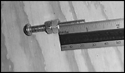
FIGURE 10.4 The nuts positioned about ![]() from the screw end.
from the screw end.
Take two wrenches (see figure 10-5) and place them over the nuts. Hold the bottom nut steady and tighten the top nut down onto it. They should be tightly butted up against each other as shown in figure 10-6.
Now insert the bolt into the cap as shown in figure 10-7 and push it as far as you can through the hole you drilled earlier.
Use the same double-nut binding technique on two nuts above the cap (see figure 10-8). Before you use the binding technique, make sure the lower nut is tight against the cap. This will prevent the bolt from spinning in the cap which could cause the camera to turn.
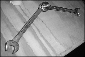
FIGURE 10.5 Use two wrenches to turn the nuts in opposite directions.

FIGURE 10.6 The two nuts tightly butted up against each other.
FIGURE 10.7 Insert the bolt with the nuts into the mounting cap.
Once the bolt is securely in place, you only need to the place the washer on the end of the bolt to have a complete cap (shown in figure 10-9). The rest of the assembly of the head is simple.
The 4″ pipe length shown in figure 10-10 will form the main part of the head. You can use a shorter length if you want, but the 4″ length allows you to easily use the head as a small hand-held mount if necessary.
When you purchase a union at the hardware store, it comes as a single unit. However, it is actually made up of three separate pieces (see figure 10-11).
When assembled (figure 10-12), the union has two threaded female ends. One end will be attached to the body pipe and the other to the head.
Screw the 4″ pipe into one end of the union. Then screw the cap onto the other end of the pipe. Your complete head should look like the one shown in figure 10-13.
Screw the protruding bolt into your camera mount socket to test it. Don’t forget the washer between the top nut of the head and the bottom of the camera. Some cameras have a breakaway socket to prevent damage to the camera. If there is a shock to the camera or too much pressure placed on it, the socket will release and may drop your camera, so be careful. The washer will help stabilize the camera and spread the pressure over a wider area. You should be able to hold the camera as shown in figure 10-14.
FIGURE 10.8 Use the same double-nut binding technique on two nuts above the cap.
FIGURE 10.9 Place the washer on the end of the bolt to have a complete cap.
FIGURE 10.10 The 4″ pipe length will form the main part of the head.

FIGURE 10.11 The three separate pieces of a union.

FIGURE 10.12 An assemble has two threaded female ends.
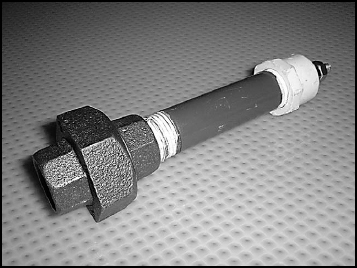
FIGURE 10.13 A complete camera glider head.

FIGURE 10.14 Holding the head of the glider.
Assembling the body
The body doesn’t require much construction; it’s mostly assembly of the various parts. First, slide the proper amount of weight to counter-balance your camera onto the body pipe.
| TIP | The camera glider can get awfully heavy for the camera operator. It’s a good idea to plan glider shots for the beginning of the day when the operator will be most rested. Also, since the glider shots are often difficult to get right, they’re good to get in the can early. |
Take the flange (like the one shown in figure 10-15) and screw it to the bottom of the body pipe.
The flange should be positioned under the weights as shown in figure 10-16. The iron weights will sit on top of the flange when you’re using the glider. If the center holes in the weights are much bigger than the diameter of the body pipe, wrap the top of the flange and the body pipe with duct tape. This will help prevent the weights from sliding. It will also silence them when you’re moving, so they don’t end up on the soundtrack.
Finally, screw the bottom of the union onto the top of the body pipe and you’re ready to go! By using a union, you can easily remove it from the body and re-attach it moments before filming must begin. Figure 10-17 shows the head and the body separated at the union.
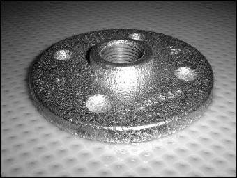
FIGURE 10.15 Flange that will be attached to the bottom of the body pipe.

FIGURE 10.16 Screw on the bottom flange after the weights have been placed on the body pipe.

FIGURE 10.17 The head and the body of the glider separated at the union.
Using the Glider
Once you have the glider completely assembled and the camera mounted on the head, you’re ready to go to work!
Grasp the body pipe about one-third of the way down from the top. When you walk, your objective is to walk as smoothly as possible. Because of the weight, you may need to grasp the holding arm with your other hand to keep it steady. Try to avoid using both hands on the body of the glider. Holding both hands on the body pipe limits the amount of pivot that is possible to soften movement. This generally leads to footage that is less fluid than the single-handed technique.
For safety, always walk the intended path before you’re carrying the weight of the camera. This will help you understand how best to approach the path. It will also give you time to remove obstacles that could cause you to trip.
Suggestions
Here are a few operating suggestions to help you get the best use from your new camera glider:
• Glue rubber to the top of the support washer This will help the washer grip more effectively to the bottom of the camera. You can glue on a rubber washer or simply cut a piece of a disposable wash glove to the proper size and use that.
• Practice, practice, practice! Don’t wait for the day of the shoot to practice how the shot will be made, do it in advance. The type of terrain you need to move over will have a great effect on the best method of holding the glider as well as helping you decide which length of body pipe will be best suited to the situation.
• Create a grip on the body pipe to prevent your hands from slipping Layers of duct tape can be built up to create a makeshift grip. Better yet, cut up a disposable wash glove up and tape it around the pipe. Rubber provides an excellent gripping surface.
• You can also create a grip using an electrical clamp These clamps are available in the electrical supply area of most hardware stores. The advantage of the clamp is that once the screw is loosened, the half of the clamp head can be pivoted to take it off or move it along the length of pipe. See Chapter 11 on the tripod glider for a complete example.