

C-stand
Applications
The C-stand (properly named the Century Stand for its hundreds of uses) is the film industry workhorse for holding flags, diffusion, backdrops, set pieces, and sometimes small lights. Figure 32-1 shows a standard C-stand with its tri-leg base, two risers (extensions), and head with extendable arm. When I made the transition from making my own movies to the professional world of filmmaking, it was clear to me that the humble C-stand was the item most critical to low-budget filmmaking and yet also the most unknown outside the professional ranks.

FIGURE 32.1 The C-stand is the film industry workhorse for holding flags, diffusion, backdrops, set pieces, and sometimes small lights.
While a C-stand is almost required equipment on sets from high to low budget, it can be prohibitively expensive to buy (a single used C-stand costs about the same as a mid-range DVD player). Since it’s usually handy to have about three of them for even a minimal shoot, it’s more affordable to make your own. While the C-stand you’ll build in this chapter is not as quick to configure as a professional stand, your custom-built stands will have two big advantages: they’re cheap and they can be more portable than a professional stand when you don’t have a grip truck to haul them around.
PARTS
| Qty | Item |
| 4 | PVC T-joints |
| 4 | |
| 4 | |
| 1 | |
| 4 | |
| 1 | Sheet of non-slip material |
| 2 | |
| 1 | |
| 1 | |
| 4 | |
| 4 | |
| 2 | |
| 1 | |
| 1 | |
| 4 | Small dumbbell weights |
General Instructions
Some of the traditional uses of the C-stand can be seen in the following figures. Figure 32-2 shows a stand being used with a flag to block off light from spilling onto the background. Flags are also commonly used to shield the camera from the sunlight (much like a matte box) and crew members from the wind or sun (known as a courtesy flag). Flags can be used as a “lenser” to block a light source from shining directly into the optics of a camera and creating artifacts such as a lens flare.
Figure 32-3 shows the stand holding a reflector that might provide a fill light for an actor. C-stands are perfect for quickly placing and stably holding reflectors in place. They are also commonly used to hold diffusion material in front of a light.
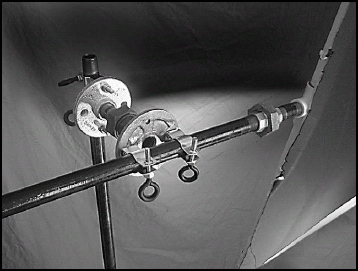
FIGURE 32.2 A flag blocks off light from spilling onto the background.
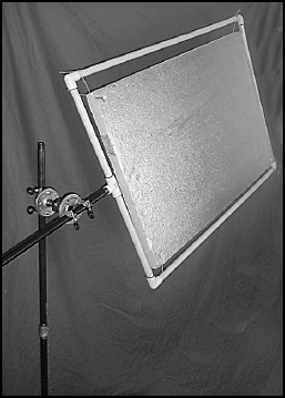
FIGURE 32.3 Holding a reflector to provide fill light for an actor.
Figure 32-4 shows a small fill light attached to the stand. The stand allows the height and angle of the light to be quickly altered. Note that you shouldn’t use the stand for any heavy or large lights as the stand isn’t intended to handle heavy weights.
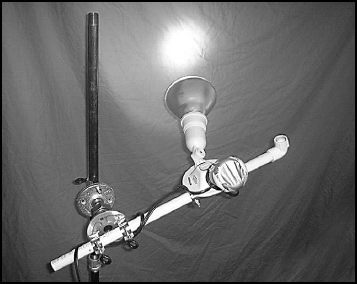
FIGURE 32.4 A small fill light attached to the stand.
Another very common use is to utilize two stands to hold up a backdrop. While a colored backdrop is often used for interviews, the C-stand rig most commonly holds a large sheet of duvetyn (black cloth) to block light from coming in a window. The light that must be blocked may be ruining the light balance of an interior shot or you may be filming a day-for-night scene.
These instructions show you how to construct a very modular stand that is easy to use. Most of the construction for the stand involves screwing various pipes together. The stand can be disassembled in the same way – consequently providing the stand’s great portability. Basic breakdown consists of unscrewing the post from the base and disassembling the segments of the post into lengths that will fit into your vehicle.
Assembling the base
To create the C-stand, you’ll begin by putting together the base that will hold the rest of the structural pipe. Figure 32-5 shows a top view of the assembled base. The central hub of the base is made of two flanges that sandwich a four-way pipe coupling between them. Four bolts run through the flange holes and secure the two flanges together.
To create the hub, follow these steps:
1. Cut two pieces of non-slip material large enough to cover the top and bottom of the four-way coupling. Non-slip material is available at most dollar stores and hardware warehouses. The material will prevent the coupling from slipping between the two flanges.
2. Place the flanges on either side of the non-slip material with the threaded couplings face out. You should now have a sandwich that consists of a flange, non-slip sheet, four-way coupling, non-slip sheet, and flange.
3. Insert the four 2![]() machine screws through the bottom flange holes and feed them up through the top flange holes. These screws should fit perfectly between the cross members in the coupling such that all four threaded opening face outward unimpeded.
machine screws through the bottom flange holes and feed them up through the top flange holes. These screws should fit perfectly between the cross members in the coupling such that all four threaded opening face outward unimpeded.
4. Place a nut on each screw and tighten it down. Your completed hub should look like the one shown in figure 32-6.
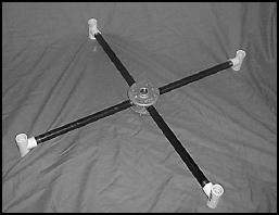
FIGURE 32.5 A top view of the assembled base.
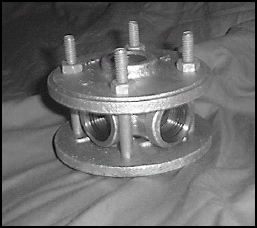
FIGURE 32.6 The completed hub.
Once the hub is complete, you’ll need to screw the four 12″ iron pipes into the coupling to form the legs. Screw these pipes as tightly as possible. Since the legs and the hub provide the main structural strength of the stand, you might even consider using some type of locking compound to ensure that none of the legs become accidentally unscrewed.
Finally, you need to add the four leg risers. These risers are made using the ![]() PVC T-joints (see figure 32-7) that are screwed onto the ends of each of the four pipes. You might have noticed the screw mount of the bottom flange prevents the stand from sitting levelly on the floor. The risers provide the clearance from the floor to allow the stand to sit evenly.
PVC T-joints (see figure 32-7) that are screwed onto the ends of each of the four pipes. You might have noticed the screw mount of the bottom flange prevents the stand from sitting levelly on the floor. The risers provide the clearance from the floor to allow the stand to sit evenly.
Cut two 3″ lengths of ![]() PVC pipe. Since the risers are actually T-joints, they will accept this small piece of PVC pipe. Insert these small PVC pipes into the top of one of the risers (see figure 32-8) and another riser on the exact opposite side of the hub.
PVC pipe. Since the risers are actually T-joints, they will accept this small piece of PVC pipe. Insert these small PVC pipes into the top of one of the risers (see figure 32-8) and another riser on the exact opposite side of the hub.
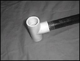
FIGURE 32.7 Add four leg risers made using the ![]() PVC T-joints.
PVC T-joints.
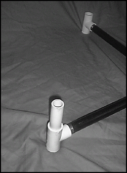
FIGURE 32.8 Insert small PVC pipes into the top of the risers.
These small pipes provide the stubs where you’ll place weights to hold down the stand. Place some small dumbbell weights on each of the weight stubs (see figure 32-9). The holes of standard dumbbells are the perfect size to accept a ![]() PVC pipe. If you don’t have any spare weights sitting around, cheap weight sets can be commonly found at garage sales and listed in the classified ads.
PVC pipe. If you don’t have any spare weights sitting around, cheap weight sets can be commonly found at garage sales and listed in the classified ads.
Be sure to place an equal amount of weight on the opposite stub (see figure 32-10). You may want to place stubs and weights on the other two risers if your stand will be handling a heavier load.

FIGURE 32.9 Place small dumbbell weights on each of the weight stubs.
The T-joints have one further use. Often you’ll find you need to place two stands in very close proximity. For example, one stand might hold a small light and another stand must hold the diffusion material directly in front of the light. As they are now, it would be difficult to place the stands close together without overlapping that can jeopardize the stability of both stands.

FIGURE 32.10 Be sure to place the equal amount of weight on the opposite stub.
A solution is to cut four small 3″ lengths of PVC pipe and insert them into the bottoms of each of the T-joints for one of the stands. The pipes will raise the stand high enough so that the legs of one stand can be placed over the legs of another (see figure 32-11).
| TIP | The risers, made of PVC plastic, provide a surface that will minimize the potential of the stand scratching a wooden floor. You might glue a soft wooden base or non-slip surface to the bottom of each riser to further prevent any possibility of floor damage. |
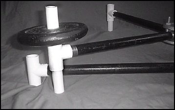
FIGURE 32.11 These pipes will raise the stand high enough for the legs to be placed over another stand.
The post requires either a very small amount of assembly or none at all. Depending on your needs, you’ll have to decide how long to make the central post and how many segments you’ll need to attain the desired height. Typically, yard-long (1 m) iron pipes are used for the stem. These pipes can be replaced easily with a single 6′ (2 m) iron pipe if this length is convenient for you to transport. Likewise, smaller 2′ pipes could be used if even more portability is necessary.
Most likely, you’ll want to create a post about 8 ft high. This size allows you to handle almost any lighting situation including the placement of a diffusion panel overhead to filter the sunlight striking a 6 ft tall actor. To achieve this height, you’ll need two 3′ pipe segments, one 2′ pipe segment, and two joint connectors. When I assemble this type of stand, I generally put the 2′ segment on the bottom, attach a 3′ segment, and keep the final segment in reserve in case I need it (see figure 32-12).
Although this setup is the most convenient, there is a reason for wanting a long single-length post. The stand head is attached to the post and then slides up and down until the desired height is reached for the flag, diffusion, etc. When using a single post stand, a single adjustment allows you to move the head from a level close to the ground all the way to the top of the pole.

FIGURE 32.12 Put the 2′ segment on the bottom and attach a 3′ segment above it.
When the segments are broken up by connecting joints, the head can only be moved up and down the length between each joint. To position it elsewhere, the joint must be removed and the head re-attached to another segment. In practice, I haven’t found this situation to occur very often and when it does, it’s usually easy to remedy quickly. However, it’s important to consider this predicament and plan ahead for it when performing setup on your stands (e.g., make sure to have at least one head on a low post).
| TIP | It is generally a good idea to either spray the threads of the main post segments with a rust inhibitor or to oil them. This type of steel can easily rust if used or stored in damp conditions. By coating them against rust, you will save yourself the unpleasant circumstance of the rust either preventing the rods from being screwed together or from taking them apart. |
Assembling the head and arm
The arm of the stand will actually carry a majority of the load of the stand. Since the arm is assembled from readily available parts, it is not as versatile as a custom-manufactured C-stand arm. Therefore, even if you’re comfortable using a professional stand arm, be sure to practice with the new arm before the shoot. That way you can understand the strengths and the limitations of this arm.
1. Take the union and screw one 1″ nipple into each side. Secure each nipple with the liquid bond-soldering agent. Using the bonding agent will prevent loosening of the shoulder joints and ensure all the torque placed on the arm will be transferred to the union.
2. Screw the other end of each nipple into a flange (see figure 32-13). Secure the flanges with the liquid bond-soldering agent.
3. Attach two conduit hangers on each flange.
4. Replace the screws in each conduit hanger with eyebolts (using the same method shown in Chapter 11).With the eyebolts you can quickly and easily tighten or loosen the brackets to slide them up and down the post.
5. Slide the brackets of the first flange over the central post of the stand (see figure 32-14).
6. Slide the rod that will be used as the arm into the brackets (see figure 32-15).

FIGURE 32.13 Screw the other end of each nipple into a flange.
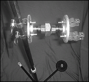
FIGURE 32.14 Slide the brackets of the first flange over the central post of the stand.
Now that your C-stand is complete, you will need to construct some flags and diffusion frames (see Chapter 45) to use it properly. When you want to tighten the arm, position the angle where you want it, tighten the ring of the union, and then hold onto the ring as you push the arm slightly downward (see figure 32-16). This will tighten the union to hold the arm precisely in place.

FIGURE 32.15 Slide the arm rod into the brackets.

FIGURE 32.16 Hold the ring as you push the arm slightly downward.
Be careful not to overload the arm. Not only might the stand tip over, but the force downward will tighten the screw of the union. If a large amount of weight is used, the union may be screwed down so tight that it is difficult to loosen. I did this once and it took a pipe wrench to break the union free.
Here are a few operating suggestions to help you get the best use from the C-stand:
• Use more base weight than you need C-stands get bumped into, overloaded, and unbalanced. The rule of thumb is to place more weight (in the form of sandbags or dead weight) on the base than absolutely necessary in order to accommodate unexpected shocks and weights.
• Make more C-stands Because of the variety of uses for a C-stand, you’ll find that you’re almost always one short. Therefore, build as many stands as you can afford to make and transport.
• Don’t use PVC in key places It’s tempting because of the low price, lightweight, and seeming durability of PVC to substitute it for some of the joints and poles, but don’t. When PVC breaks, it simply shears off dropping everything attached to it to the ground (including lights, flags, false walls, etc.). You don’t want equipment ruined or actors harmed because substandard materials were used in construction.