
Reflector/Shiny Board
Applications
For exterior shoots, one of the most useful pieces of equipment in the grip truck is the reflector or shiny board (see figure 35-1). A reflector is essentially a large soft mirror that can be used to reflect the sun into a scene. The reflector can be panned and tilted and once properly positioned, locked into place. Shiny boards provide a fantastic way to light a scene without using a full lighting package.
As opposed to attaching a large piece of reflector fabric to an 8′ × 8′ frame, a shiny board is smaller (generally 3′ × 3′) and made to be specifically targeted on an area, and re-targeted. Generally one person is assigned to the reflector so that when the sun moves, adjustments can be made to keep the highlight in the same place.
A shiny board is mounted on a head, so it can be quickly panned left or right. The reflector board itself is attached to a swivel head, so it can be tilted for correct light placement. Most exterior shots benefit from the use of a reflector to add a little brightness to the scene, a rim light to an actor, or highlight detail in the background.
PARTS
| Qty | Item |
| 6 | |
| 2 | |
| 2 | |
| 4 | 1″ to |
| 1 | 1″ coupling |
| 2 | |
| 1 | |
| 1 | |
| 1 | |
| 1 | |
| 1 | |
| 1 | |
| 3 | |
| 1 | C-stand base (see Chapter 43) |
General Instructions
A shiny board should have two sides: a hard side and a soft side. The soft side can be provided with aluminum foil. For the hard side, you’re going to have to purchase a sheet of Mylar (available at most party stores). You may want to scuff the Mylar surface a bit to make sure the reflected light isn’t too harsh. For the board itself, an insulation panel is nearly perfect. One of the advantages of using insulation panels is that they’re sturdy enough to withstand the wind without bending, yet they’re still fairly light.
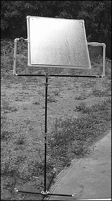
FIGURE 35.1 For exterior shoots, one of the most useful pieces of equipment is the reflector or shiny board.
The reflector is typically mounted on a sturdy junior stand. Since the board is used outside and has such a broad flat surface, wind can easily catch it and knock it over. The shiny board you’ll create in this chapter will be mounted on the C-stand you created in Chapter 32. Since the C-stand isn’t very heavy, make sure you excessively weight down the base to make certain that the stand isn’t blown over. Additionally, bring along some spare rope you can use to secure the frame to nearby buildings or fences.
You can see a complete diagram for the shiny board in figure 35-2. The union at the bottom allows the frame to pan and adjust the reflected light to the left or the right. The assembly on the left side of the frame is essentially a socket that allows the panel to be tilted or even freely spun end over end. The assembly uses a nail like a cotter pin to secure the tilt at a particular angle.
On the right side, a plastic union has been modified to allow the panel to freely rotate. While the right side union can be replaced with an assembly like the one used on the left side, the assembly is more expensive and complicated to make than simply purchasing a union.
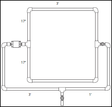
FIGURE 35.2 A complete diagram for the shiny board.
For stability, be sure to use PVC cement on all the (non-rotating) pieces to make sure the structure is solid. As always, don’t glue on piece that makes the assembly of another piece impossible. For example, don’t glue the reflector mount together before you place the reflector panel between the union and the left assembly or you won’t be able to insert the frame.
Creating the base
Start by creating the base of the reflector. It’s the same construction as the one used for the C-stand. Turn to Chapter 32 for instructions and construct the base, so it appears as the one shown in figure 35-3.
Once you have the base assembled, be sure to purchase enough lengths of pipe to raise it high. You will also probably need more height than the C-stand as a shiny board is often extended to 8–10 ft (about 3 m) in height. Since a shiny board needs to be in the light to direct it, this often means catching light over small trees, fences, and other obstacles.
| TIP | If you’ll be working with the reflector a great deal (re-positioning, moving, re-directing, etc.), be sure to bring along a stepladder. You may need to put it higher than is convenient to reach. |
Creating the reflector panel
The reflector panel can be made of any type of thick Styrofoam board. I’ve found that insulation board is about an inch thick (2.5 cm) making it the perfect thickness for this application.
To create the reflector panel, follow these steps:
1. Cut a piece of insulation foam into a square 3′ × 3′ (1m × 1m). Most of the standard size boards at the hardware store are 2′ × 4′, so you might have to go to a home warehouse supply to buy the large sizes to trim down. Otherwise, patch two smaller boards together to obtain the correct size.
2. Cut lengths of ![]() PVC pipe to the following measures: two lengths of 36″ (1 m) and four lengths of 17″ (43 cm).
PVC pipe to the following measures: two lengths of 36″ (1 m) and four lengths of 17″ (43 cm).
3. Create the frame with four 90° elbows and two T-joints as shown in figure 35-4.
4. Place the foam square into the frame and make sure it fits snugly. If not, trim the PVC pipes until the frame is the right size.
5. Attach the aluminum foil to one side and the Mylar to the other. Although I’ve found it easiest to simply staple the reflecting sheets onto the insulation board, attachment with glue might be more durable.
6. Drive screws through the frame into the insulation board (see figure 35-5). I used 3″ (7.5 cm) drywall screws to act like pins to hold the insulation board in place. I only needed two screws per side of the frame to steadily anchor the board, so it didn’t move. Use as many as you feel are necessary. Be sure to drill holes through the PVC pipe before you drive the screws through to make sure they go straight into the insulation board.
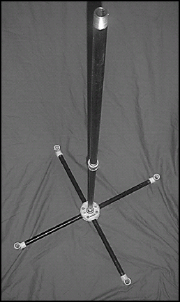
FIGURE 35.3 The base of the reflector is identical to the one used for the C-stand.
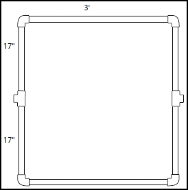
FIGURE 35.4 Create the frame with four 90° elbows and two T-joints.
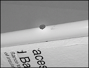
FIGURE 35.5 Drive screws through the frame into the insulation board.
Once the panel is complete, you’ll begin construction on the reflector mount. The mount will allow the reflector panel to tilt.
Creating the reflector mount
The mount is the most complicated part of the reflector. The mount must allow the reflector to be spun freely since either the soft or hard side might be chosen for a particular shot (and may be called for at any time). However, once the soft or hard side has been chosen and a reflector angle selected, the reflector must be locked into that angle and stay solidly in place despite wind or other factors.
We’ll start by creating the left assembly. The left assembly is shown in figure 35-6. From left to right, the assembly consists of: a short length of ![]() PVC (attached to the panel’s T-joint), a
PVC (attached to the panel’s T-joint), a ![]() threaded adapter, a 1″ to
threaded adapter, a 1″ to ![]() adapter, a 1″ coupling, a 1″ to
adapter, a 1″ coupling, a 1″ to ![]() adapter, a
adapter, a ![]() threaded adapter, a short length of
threaded adapter, a short length of ![]() PVC, and a 90° elbow. You may not be able to see the first short length of PVC pipe since in the figure it’s joining the threaded adapter to the T-joint of the panel frame.
PVC, and a 90° elbow. You may not be able to see the first short length of PVC pipe since in the figure it’s joining the threaded adapter to the T-joint of the panel frame.

FIGURE 35.6 Create the left assembly.
Before you begin assembly, some modifications need to be made to the 1″ coupling and one of the 1″ to ![]() adapters. To make things easier, first take one of the 1″ to
adapters. To make things easier, first take one of the 1″ to ![]() adapters and use PVC cement to glue it into one side of the coupling. The glued adapter will remain stationary with the frame while the other adapter spins to allow the panel to spin.
adapters and use PVC cement to glue it into one side of the coupling. The glued adapter will remain stationary with the frame while the other adapter spins to allow the panel to spin.
Take the coupling and sand out the open end. Sanding off a small layer will create enough room for the second adapter to spin freely within it. Don’t sand so much that the adapter is loose in the coupling end. Don’t worry if the adapter seems a little tight since you’ll be putting some oil into it later to reduce the friction.
Insert the second adapter into the coupling and drill a small hole through the coupling into the adapter (see figure 35-7). In this hole you’ll insert a nail to use as a cotter pin to hold the panel at a selected angle.
Withdraw the second adapter and you should see the hole generated by drilling through the coupling. Measure the distance from the end of the adapter to this hole. All the holes you drill in the adapter should be at the same distance from the end. You should now drill holes around the barrel of the adapter (see figure 35-8). For my reflector, I drilled 12 holes allowing me to position the panel in 30° increments (360°/12 holes = 30° between holes). Drill more or less holes depending on your needs.
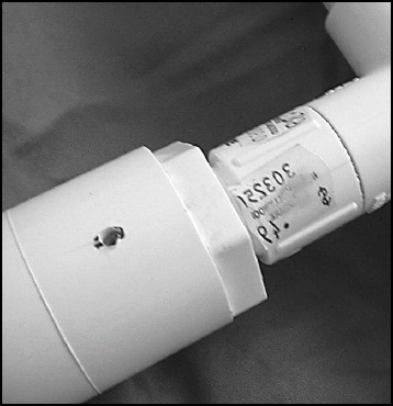
FIGURE 35.7 Insert the second adapter into the coupling and drill a small hole through the coupling into the adapter.

FIGURE 35.8 Drill all the holes around the barrel of the adapter.
| TIP | I’ve found that the easiest way to obtain evenly spaced holes is to wrap a small sheet of paper around the pipe. On the paper, place a mark on the paper where the wrapping overlap occurs. Unroll the paper and you should have a mark that indicates the complete circumference of the pipe. Use a ruler to measure this length and divide the value the number of holes you need. Make marks on the paper at the appropriate intervals (the end of the paper will indicate the first marker). Wrap the paper around the pipe again and mark on the pipe where the holes should go. |
Once all the holes are drilled, place the adapter back into the coupling and try to insert the nail at each of the increments. If the nail won’t enter, you may have to widen either the hole on the coupling or some of the holes in the adapter. Make sure you don’t widen the holes too much so that you don’t have a snug fit or your panel may move when the wind hits it.
Rub a small amount of oil for lubrication on the inside of the coupling. Put the assembly together as shown in figure 35-9. It’s a good idea to use PVC cement to glue together all the parts except for the coupling and the second adapter (which should spin freely). If you’re not sure you understand how the mount will go together, wait to glue until you can see how you’ll complete the construction.
To create the other side of the panel mount, you’ll need to make a slight modification to the plastic union piece. In figure 35-10, you can see that the union, when disassembled, is actually three different pieces. The piece on the left has no threads and spins freely in the union. The threaded piece on the right is screwed into the housing (the center object) and can be tightened down until the unthreaded piece can’t move. You’re going to use PVC cement to bond the threaded piece to the housing such that the unthreaded piece can still spin freely.

FIGURE 35.9 Put the assembly together.
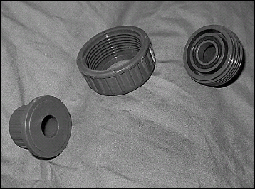
FIGURE 35.10 The three different pieces of a disassembled union.
Before you get out the glue, try tightening down the threaded piece. Do you feel how the unthreaded piece can’t move? Now back off the threaded piece enough, so the unthread piece can freely move (about a quarter turn with the union I’ve used). Do you feel how the unthreaded piece can spin freely? That’s how you’re going to create a freely revolving socket.
First, disassemble the union and take out the unthreaded piece. Apply some oil to the rim to ensure the piece will rotate smoothly. Place the unthreaded piece back into the housing. Remember PVC cement dries very quickly, so you’ll have to work fast on this next part.
Put PVC cement on the threads of the threaded part. Screw it all the way into the housing and then back it out the number of turns to keep the unthreaded part free (probably a quarter turn). Now grasp the housing and spin the unthreaded part to make sure the PVC cement didn’t get on that part (and bind it to the housing). The cement should set in under a minute and you now have a freely rotating socket!
When the union is mounted on the other side of the panel, it will appear as shown in figure 35-11.

FIGURE 35.11 The union mounted on the other side of the panel.
Next you’ll put together the main head bracket that uses iron pipes to hold up the panel. Since it uses fixed length iron pipes, you will want to wait to complete the panel mounting because you will need to cut the final PVC pipes to make it fit the bracket.
Mounting the panel
The assembly of the main head bracket consists mostly of screwing together various parts.
1. Screw the steel union onto the top of the pipe on the base of the stand.
2. Screw the 3″ steel pipe nipple into the top of the union.
3. Mount the four-way steel joint onto the top of the nipple. You can use a T-joint instead, although I chose the four-way to have an extra position for placing a securing rope.
4. Screw the 12″ pipe into one end and the 36″ pipe in the other end of the four-way joint (see figure 35-12).
5. Add a threaded 90° elbow at the ends of the pipes. Note that I used these PVC elbows because they were available with one end threaded and the other plain to allow easy insertion of the panel mount. You can use a metal elbow instead, but you’ll also have to add thread adapters to the ends of the PVC pipes on the mount.
6. Measure the length between the two elbows on the bracket.
7. Complete assembly of the mount (see figure 35-13) and make it match the length of the mounting bracket by cutting the PVC lengths on the left and right ends just before the 90° elbows.
8. Cut two PVC lengths that provided enough room between the panel 90° elbows and the top of the bracket (see figure 35-13).
9. Insert the lengths into the elbows and put the entire panel mount onto the bracket (see figure 35-14).
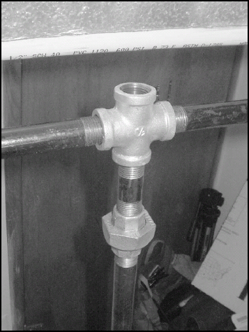
FIGURE 35.12 Screw the 12″ pipe into one end and the 36″ pipe in the other end of the four-way joint.
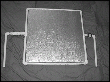
FIGURE 35.13 Complete assembly of the mount.
Your reflector is now complete. It is a good idea to use some string to attach the nail/cotter pin to the frame, so it won’t get lost. For transporting the reflector, it can be easily broken down into three pieces. Unscrew the bracket at the metal union and the whole head will come free as one piece. Unscrew the rod for the second piece. The base is the third piece.
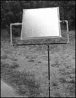
FIGURE 35.14 Cut two PVC lengths that provided enough room between the panel 90° elbows and the top of the bracket.
Suggestions
Here are a few operating suggestions for the reflector:
• Light the background Reflectors aren’t often used to light the main actors (except as a fill light). Most often, the actors are placed in the direct light, perhaps with a sheet of diffusion on a frame between them and the sun. The shiny board can then be used to add a rimlight, provide a background pattern in conjunction, or highlight features of the background that sit in shadow.
• Position the reflector with a hand Especially with the soft side, it’s often difficult to accurately position the center of the reflection. Have someone stand in the scene with their fist where the light should be focused. Then you have an easy target to concentrate the light on.