
- Cover
- Half Title
- Title Page
- Copyright Page
- Table of Contents
- Foreword
- Preface
- Author
- 1. Fundamentals of Electric Field
- 1.1 Introduction
- 1.2 Electric Charge
- 1.3 Electric Fieldlines
- 1.4 Coulomb’s Law
- 1.5 Electric Field Intensity
- 1.6 Electric Flux and Electric Flux Density
- 1.7 Electric Potential
- 1.8 Field due to Point Charge
- 1.9 Field due to a Uniformly Charged Line
- 1.10 Field due to a Uniformly Charged Ring
- 1.11 Field due to a Uniformly Charged Disc
- Objective Type Questions
- Bibliography
- 2. Gauss’s Law and Related Topics
- 2.1 Introduction
- 2.2 Useful Definitions and Integrals
- 2.3 Integral Form of Gauss’s Law
- 2.4 Differential Form of Gauss’s Law
- 2.5 Divergence Theorem
- 2.6 Poisson’s and Laplace’s Equations
- 2.7 Field due to a Continuous Distribution of Charge
- 2.8 Steps to Solve Problems Using Gauss’s Law
- Objective Type Questions
- 3. Orthogonal Coordinate Systems
- 4. Single-Dielectric Configurations
- 5. Dielectric Polarization
- 5.1 Introduction
- 5.2 Field due to an Electric Dipole and Polarization Vector
- 5.3 Polarizability
- 5.4 Field due to a Polarized Dielectric
- 5.5 Electric Displacement Vector
- 5.6 Classification of Dielectrics
- 5.7 Frequency Dependence of Polarizabilities
- 5.8 Mass-Spring Model of Fields in Dielectrics
- 5.9 Dielectric Anisotropy
- Objective Type Questions
- 6. Electrostatic Boundary Conditions
- 7. Multi-Dielectric Configurations
- 8. Electrostatic Pressures on Boundary Surfaces
- 8.1 Introduction
- 8.2 Mechanical Pressure on a Conductor–Dielectric Boundary
- 8.3 Mechanical Pressure on a Dielectric–Dielectric Boundary
- 8.4 Two Dielectric Media in Series between a Parallel Plate Capacitor
- 8.5 Two Dielectric Media in Parallel between a Parallel Plate Capacitor
- Objective Type Questions
- 9. Method of Images
- 9.1 Introduction
- 9.2 Image of a Point Charge with Respect to an Infinitely Long Conducting Plane
- 9.3 Image of a Point Charge with Respect to a Grounded Conducting Sphere
- 9.4 Image of an Infinitely Long Line Charge with Respect to an Infinitely Long Conducting Plane
- 9.5 Two Infinitely Long Parallel Cylinders
- 9.6 Salient Features of Method of Images
- Objective Type Questions
- 10. Sphere or Cylinder in Uniform External Field
- 11. Conformal Mapping
- 12. Graphical Field Plotting
- 13. Numerical Computation of Electric Field
- 14. Numerical Computation of High-Voltage Field by Finite Difference Method
- 14.1 Introduction
- 14.2 FDM Equations in 3D System for Single-Dielectric Medium
- 14.3 FDM Equations in Axi-Symmetric System for Single-Dielectric Medium
- 14.4 FDM Equations in 3D System for Multi-Dielectric Media
- 14.5 FDM Equations in Axi-Symmetric System for Multi-Dielectric Media
- 14.6 Simulation Details
- 14.7 FDM Examples
- Objective Type Questions
- Bibliography
- 15. Numerical Computation of High-Voltage Field by Finite Element Method
- 15.1 Introduction
- 15.2 Basics of FEM
- 15.3 Procedural Steps in FEM
- 15.4 Variational Approach towards FEM Formulation
- 15.4.1 FEM Formulation in a 2D System with Single-Dielectric Medium
- 15.4.2 FEM Formulation in 2D System with Multi-Dielectric Media
- 15.4.3 FEM Formulation in Axi-Symmetric System
- 15.4.4 Shape Function, Global and Natural Coordinates
- 15.4.5 Derivation of Field Variables Using Natural Coordinates
- 15.4.6 Other Types of Elements for 2D and Axi-Symmetric Systems
- 15.4.7 FEM Formulation in 3D System
- 15.4.8 Mapping of Finite Elements
- 15.5 Features of Discretization in FEM
- 15.6 Solution of System of Equations in FEM
- 15.7 Advantages of FEM
- 15.8 FEM Examples
- Objective Type Questions
- Bibliography
- 16. Numerical Computation of High-Voltage Field by Charge Simulation Method
- 16.1 Introduction
- 16.2 CSM Formulation for Single-Dielectric Medium
- 16.3 CSM Formulation for Multi-Dielectric Media
- 16.4 Types of Fictitious Charges
- 16.5 CSM with Complex Fictitious Charges
- 16.6 Capacitive-Resistive Field Computation by CSM
- 16.7 Field Computation by CSM under Transient Voltage
- 16.8 Accuracy Criteria
- 16.9 Other Development in CSM
- 16.10 Comparison of CSM with FEM
- 16.11 Hybrid Method Involving CSM and FEM
- 16.12 CSM Examples
- Objective Type Questions
- Bibliography
- 17. Numerical Computation of High-Voltage Field by Surface Charge Simulation Method
- 17.1 Introduction
- 17.2 SCSM Formulation for Single-Dielectric Medium
- 17.3 Surface Charge Elements in 2D and Axi-Symmetric Configurations
- 17.4 SCSM Formulation for Multi-Dielectric Media
- 17.5 SCSM Formulation in 3D System
- 17.6 Capacitive-Resistive Field Computation by SCSM
- 17.7 SCSM Examples
- Objective Type Questions
- Bibliography
- 18. Numerical Computation of Electric Field in High-Voltage System – Case Studies
- 18.1 Introduction
- 18.2 Benchmark Models for Validation
- 18.3 Electric Field Distribution in the Cable Termination
- 18.4 Electric Field Distribution around a Post-Type Insulator
- 18.5 Electric Field Distribution in a Condenser Bushing
- 18.6 Electric Field Distribution around a Gas-Insulated Substation Spacer
- Objective Type Questions
- Bibliography
- 19. Electric Field Optimization
- 19.1 Introduction
- 19.2 Review of Published Works
- 19.2.1 Conventional Contour Correction Techniques for Electrode and Insulator Optimization
- 19.2.2 Optimization of High-Voltage System Elements
- 19.2.3 Soft-Computing Techniques for Electrode and Insulator Optimization
- 19.2.4 Optimization of Switchgear Elements
- 19.2.5 Optimization of Bushing Elements
- 19.2.6 User-Friendly Optimization Environment
- 19.3 Field Optimization Using Contour Correction Techniques
- 19.4 ANN-Based Optimization of Electrode and Insulator Contours
- 19.5 ANN-Aided Optimization of 3D Electrode–Insulator Assembly
- Objective Type Questions
- References
- Index
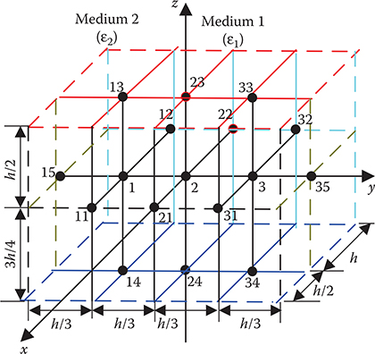
FIGURE 14.12
Nodal arrangement pertaining to Problem 14.5.

FIGURE 16.18
Simulation of a three-core belted cable by CSM using complex fictitious charges.

FIGURE 16.20
Simulation of fluid-filled outdoor cable termination by conventional CSM.

FIGURE 16.22
Simulation of an asymmetric sphere-gap arrangement by CSM.

FIGURE 17.5
Discretization of a practical multi-electrode multi-dielectric arrangement using triangular elements: (a) view 1 and (b) view 2.
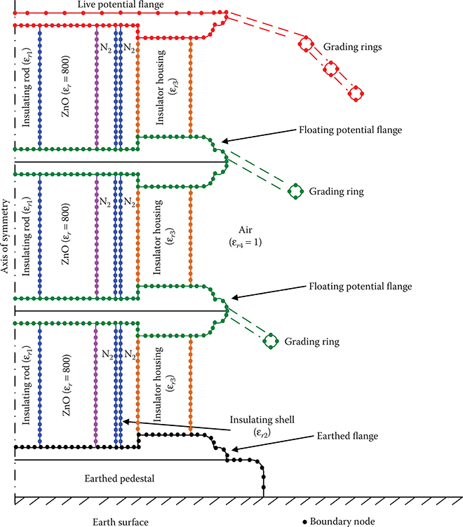
FIGURE 17.11
SCSM simulation of multiple unit assembly of metal oxide surge arrester.
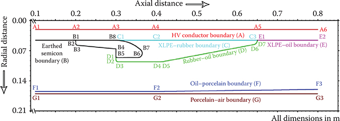
FIGURE 18.2
Geometry and boundaries of cable termination under study.
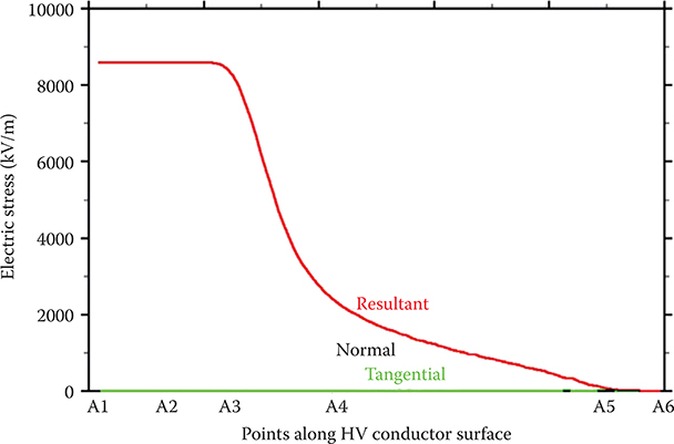
FIGURE 18.3
Electric stresses along the high-voltage conductor surface.
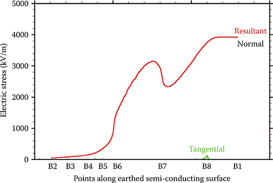
FIGURE 18.4
Electric stresses along the semi-conducting surface.
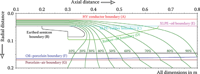
FIGURE 18.7
Equipotential lines for the cable termination.

FIGURE 18.20
GIS configuration considered for electric field computation.

FIGURE 19.21
3D electrode–support insulator assembly for optimization: (a) electrode–insulator assembly; (b) live electrode and (c) support insulator.

FIGURE 19.22
3D electrode–disc insulator assembly for optimization: (a) disc-type insulator with live and ground electrodes and (b) live electrode with sectional view of disc insulator.
-
No Comment