
8
Electrostatic Pressures on Boundary Surfaces
ABSTRACT In electrostatic field, due to the presence of surface charges on the boundary, there is always a mechanical pressure that acts on any boundary. However, the magnitude of such mechanical pressure due to electrostatic field is usually small compared to the other types of mechanical pressure that one encounters in everyday life. But the mechanical pressures due to the electrostatic field have many interesting engineering applications. Thus, it is important to derive the general expressions for mechanical pressure acting on the boundary between a perfect conductor and a dielectric as well as the boundary between two different dielectric media.
8.1 Introduction
There could be two different approaches towards the calculation of electrostatic force acting on any boundary. In the first approach, the macroscopic resultant force may be calculated by summing up the elementary electrostatic forces as obtained from Coulomb’s law. On the one hand, this approach should always give correct result, but on the other hand, in most of the practical cases, it is very difficult, if not impossible, to perform such calculation as the actual distributions of charges are mostly unknown.
The second approach is based on the principle of energy conservation and the electrostatic forces are derived indirectly from energy relationship. This approach is advantageous in the sense that the forces can be calculated conveniently even by analytical methods. But the accuracy of the results obtained from this approach depends on the validity of the principle of energy conservation for the specific case under consideration. Some argue that this condition is not always satisfied and consequently this method can lead to wrong results in some cases. Although majority of the scientific community firmly believe that the principle of energy conservation has a general validity, and therefore this approach should always provide correct results. On the whole, it is better to suggest that one should use it with due circumspection and reservation by always verifying the results.
8.2 Mechanical Pressure on a Conductor–Dielectric Boundary
As discussed in Section 6.2, only same polarity charges reside on the boundary between a perfect conductor and a dielectric medium. These same polarity charges, residing on the surface of the conductor, exert repulsive forces on each other. These forces will be of such nature that the distance between the charges should increase. In other words, the surface area of the conductor–dielectric boundary will try to increase under the influence of these repulsive forces. Hence, the electrostatic force on the conductor–dielectric boundary always acts along the normal to the boundary directed from the conductor to the dielectric.
The force on a conductor–dielectric boundary could be calculated using the expression for energy density. If an elemental area ΔA on a conductor–dielectric boundary is depressed by a distance Δl, the increase in stored energy (ΔW) is equal to the work done against the electrostatic force acting on the conductor–dielectric boundary trying to swell the surface. Hence, considering the energy density of electric field within the dielectric to be WE,
ΔW = WEΔAΔl
Here, it has been assumed that the charge on the conductor surface remain unchanged even when the geometry is changed slightly. This assumption is valid when the conductor is an isolated one, that is, it is not connected to a source that could alter its charge, for example, a voltage source. Hence, the work done in depressing the boundary could be related directly to the energy content of electric field according to the law of conservation of energy.
If the electrostatic force acting against the depression of the surface is given by F, then the work done against this force is
Electrostatic force per unit area is the mechanical pressure due to electrostatic field acting on the conductor–dielectric boundary, which is, therefore, given by
Considering the surface charge density of the conductor–dielectric boundary to be σ,
as D = Dn = σ, because Dt = εEt is zero on the conductor surface, as Et = 0.
8.2.1 Electric Field Intensity Exactly on the Conductor Surface
Dimensionally, the mechanical pressure acting on the charged conductor surface is equal to the product of surface charge density (σ) and the electric field intensity exactly on the conductor surface (Esurface), that is, from Equation 8.3
From Equations 6.8 and 6.10,
Therefore,
PROBLEM 8.1
A metallic sphere of 20 cm radius is charged with 1 μC, spread uniformly over the surface and is surrounded by a dielectric medium having a relative permittivity of 5. Find the electric field intensity just off the sphere and also on the sphere. Find also the mechanical pressure acting on the sphere.
Solution:
Sphere radius = 20 cm = 0.2 m
Sphere surface area = 4π × (0.2)2 = 0.5026 m2
Therefore, surface charge density (σ) = (1 × 10⁻⁶)/0.5026 = 1.989 × 10⁻⁶ C/m2.
Electric field intensity just off the sphere surface = (1.989 × 10⁻⁶)/(5 × 8.854 × 10−12) = 44.94 × 10³ V/m.
Electric field intensity exactly on the sphere surface = (44.94 × 10³)/2 = 22.47 × 10³ V/m.
Therefore, mechanical pressure acting on the sphere surface = 1.989 × 10−6 × 22.47 × 103 = 0.0447 N/m2.
8.2.2 Electrostatic Forces on the Plates of a Parallel Plate Capacitor
In order to get a simple analytical solution, consider that the distance between the plates (l) of the capacitor is much smaller than the area of the plates (A). In that case, it may be assumed that the E-field between the plates is homogeneous, and the effect of the inhomogeneity of E-field at the edges, commonly known as fringing, may be neglected. The charge may also be assumed to be distributed uniformly over the plates, that is, the charge density may be assumed to be known for the application of Coulomb’s law.
Capacitance of the parallel plate capacitor (C) = εA/l.
Let the potential difference between the two plates of the capacitor be V.
Therefore, the uniformly distributed charge on the plates of the capacitor (Qplate) = C × V = εAV/l and the electric field intensity within the dielectric of the capacitor (E) = V/l.
As discussed in Section 8.2.1, electric field intensity exactly on the plate surface is given by
Therefore, from Coulomb’s law, the electrostatic force acting on the capacitor plates is given by
Again, according to Equation 8.2 mechanical pressure acting on the plates
Hence, the electrostatic force acting on the capacitor plates is
which is the same as that of Equation 8.8.
Equation 8.8 is very useful because if the force could be measured when the voltage is unknown, then the voltage can be calculated from the above formula from the knowledge of the capacitor dimensions. In fact, the measurement of voltage by electrostatic voltmeter is based on this principle.
PROBLEM 8.2
For an air-filled parallel plate capacitor, the area of the plates is 50 cm2 and the separation distance between the plates is 5 mm. What will be the maximum electrostatic force on the capacitor plates at standard temperature and pressure?
Solution:
Breakdown strength of air at standard temperature and pressure (STP) is 30 kV/cm or 3 × 10⁶ V/m. That will be the maximum possible electric field intensity within the parallel plate capacitor.
Therefore, the maximum electrostatic pressure on the capacitor plates is
8.3 Mechanical Pressure on a Dielectric–Dielectric Boundary
Mechanical pressure due to electrostatic field that act on a dielectric–dielectric boundary arise due to two reasons. The first one is the polarization of atoms and/or dipoles in the volume of the dielectric media under the action of electric field, while the second one is the change in the polarization vector that takes place at the boundary between two different dielectric media. These two mechanical pressures need to be discussed separately.
8.3.1 Mechanical Pressure due to Dielectric Polarization
Consider a homogeneous isotropic dielectric piece of small volume placed in vacuum within an electric field. The atoms and/or dipoles within this dielectric volume will be polarized under the action of the electric field. Because each atom and/or dipole consists of positive and negative charge, it may be considered that under the action of the electric field a uniformly distributed cloud of negative charges is shifted through a small distance from a uniformly distributed cloud of positive charges. The same polarity charges by mutual repulsion develop an outward force, which tends to swell the small dielectric volume into the surrounding vacuum.
The dielectric volume, being small enough, will not alter the electric field intensity due to the external field within which it is placed. But due to dielectric polarization, the electric flux density within the dielectric volume will be higher due to higher permittivity of the dielectric compared to vacuum for the same electric field intensity.
In the absence of dielectric medium, energy density of electric field will be given by
and in the presence of dielectric medium, energy density of electric field for the same electric field intensity within the same volume will be given by
Due to electrostatic repulsive force, if unit area of the surface of the small dielectric volume expands through a small distance dl in the normal direction, then the difference in stored energy is equal to the mechanical work done by the repulsive forces, if no heat energy is lost. Let the force on the dielectric boundary due to dielectric polarization be Fpol. Then the mechanical work done by Fpol is given by
This force per unit area, that is, mechanical pressure, acts normally on the boundary directed from the dielectric to vacuum.
When two different dielectric meet at a boundary, then the mechanical pressure by which each dielectric tends to push the boundary normally outwards could be computed using Equation 8.12. The difference in these two pressures is the net pressure acting on the dielectric–dielectric boundary due to dielectric polarization.
The mechanical pressure on the boundary due to dielectric 1 alone, that is, when dielectric 2 is replaced by vacuum, is given by
This pressure given by Equation 8.13 acts normally from dielectric 1 to vacuum on the boundary.
Again, the mechanical pressure on the boundary due to dielectric 2 alone, that is, when dielectric 1 is replaced by vacuum, is given by
This pressure given by Equation 8.14 acts normally from dielectric 2 to vacuum on the boundary.
The difference in these two pressures as given by Equations 8.13 and 8.14 is the net pressure acting on the boundary due to dielectric polarization. Considering the normal on the dielectric–dielectric boundary to be from dielectric 1 to dielectric 2,
as E1t = E2t = Et and D1n = D2n = Dn.
8.3.2 Mechanical Pressure on Surface Film at the Dielectric–Dielectric Boundary
Consider a boundary between a homogeneous isotropic dielectric medium and vacuum, as shown in Figure 8.1. For a boundary having no free charge, the boundary conditions are E1t = E2t and D1n = D2n.
Within the dielectric medium D1 = ε1E1 = ε0E1 + P1, where P1 is the polarization vector in the dielectric medium. Hence, P1 = D1 − ε0E1.
On the other hand, within vacuum D2 = ε0E2 and hence, P2 = 0.
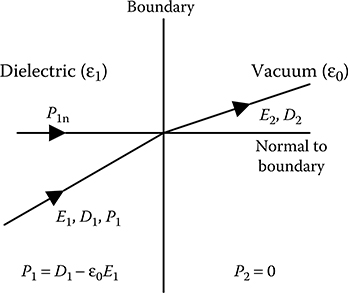
FIGURE 8.1
Change of polarization vector at dielectric–vacuum boundary.
Thus, as one crosses the boundary the polarization vector drops from a finite value within the dielectric medium to zero in vacuum. But this change in polarization vector cannot occur at one line of infinitesimal thickness representing the boundary. On the contrary, such change in polarization vector occurs within a thin film of finite but very small thickness within the dielectric medium just off the boundary.
Consequently, this boundary film needs to be studied closely. Because only a normal displacement of the boundary film will expand the boundary, only the normal components of electric flux density and polarization vector are considered. The normal component of electric flux density remains constant inside the boundary film. But, the normal component of electric field intensity as well as the normal component of polarization vector vary gradually and finally assume the values equal to those just outside the film on the vacuum side of the boundary. Such variation is schematically shown in Figure 8.2.
Within the boundary film, the polarization vector is Pn = Dn − ε0En.
Therefore, dPn = −ε0dEn as Dn is constant within the film.
Now, consider a thin strip of thickness ds within the film such that the distance of the strip from the beginning of the film is S, as shown in Figure 8.2. Also consider that ds be the separation distance between the positive and negative charges of the atoms and/or dipoles within this strip. At a distance S, the negative charges of the atoms lie in a field of intensity En and at a distance S + ds, the positive charges lie in a field of En + dEn. Hence, each dipole charge is subjected to a force per unit of dEn towards right according to Figure 8.2. But the polarization vector being Pn, there are Pn charges per unit area. Thus, the force per unit area, that is, mechanical pressure, acting towards right on the thin strip is

FIGURE 8.2
Variation of electric field quantities within the boundary film.
Therefore, total mechanical pressure acting on the entire film is
Thus, when two dielectric media meet at a boundary, the normal pressure that acts on the boundary film from dielectric 1 to dielectric 2 may be computed following the same logic as in the case of Equations 8.13 through 8.15. Therefore,
8.3.3 Total Mechanical Pressure on the Dielectric–Dielectric Boundary
Total mechanical pressure on the boundary between two dielectric media pushing the boundary from dielectric 1 to dielectric 2 is the sum of Equations 8.15 and 8.18. Therefore,
Noting that , , E1t = E2t and D1n = D2n, the above equation may be rewritten as
Equation 8.20 may also be written as
as E1t = E2t = Et and D1n = D2n = Dn
Equation 8.21 can be used to find the mechanical pressure acting on the conductor–dielectric boundary, by considering ε1 = ∞ for the conductor and noting the boundary conditions on the conductor–dielectric boundary as Et = 0 and hence D = Dn. Then putting 2 = for the dielectric surrounding the conductor in Equation 8.21
which is the same as Equation 8.3.
PROBLEM 8.3
There is a paper-insulated transformer coil immersed in oil. εr for paper = 3 and εr for transformer oil = 2.1. There is a normal electric stress of 25 kV/cm and a tangential electric stress of 10 kV/cm just within the paper at the paper–oil boundary. Calculate the total mechanical pressure acting on the paper–oil boundary.
Solution:
Given: E1n = 25 kV/cm = 25 × 105 V/m and E1t = 10 kV/cm = 106 V/m
Therefore,
D1n = εr1ε0E1n = 3 × ε0 × 25 × 105 = 75 × ε0 × 105 V/m
Total mechanical pressure acting on the paper–oil boundary
PROBLEM 8.4
A rectangular slab of porcelain (εr = 5) is placed in air within an electric field such that the surface of the porcelain slab is perpendicular to the electric fieldlines. Find the maximum possible mechanical pressure acting on the porcelain–air boundary at standard temperature and pressure.
Solution:
Because the boundary is perpendicular to the electric fieldlines in air, the air side of the boundary Et = 0. Again the maximum value of electric field intensity in air is 30 kV/cm at standard temperature and pressure. Therefore, on the air side of the boundary En−max = 30 kV/cm or 3 × 10⁶ V/m.
Therefore, the maximum possible mechanical pressure acting on the porcelain–air boundary is
8.4 Two Dielectric Media in Series between a Parallel Plate Capacitor
Consider a parallel plate capacitor having two dielectric media in series between the plates such that the boundary between the dielectric media is parallel to the plates, as shown in Figure 8.3. In this case, electric fieldlines will be perpendicular to the boundary. According to the boundary condition, normal component of electric flux density will be same in both the dielectric media, but the magnitude of electric field intensity will be different in the two dielectrics. Further, because the tangential component of electric field is zero, as the electric flux lines are perpendicular to the boundary, hence D = Dn.
Let the potential difference across the dielectric 1 (ε1) is V1 and that across the dielectric 2 (ε2) is V2. Then

FIGURE 8.3
Two dielectric media in series between a parallel plate capacitor.
Hence,
Mechanical pressure acting on the plates will be equal to energy density of electric field just off the plates, that is, (1/2)εE2. Considering the area of the plates to be A,
Mechanical force acting on the top plate
where:
Similarly, mechanical force acting on the bottom plate
The force F1 acts on the top plate directed towards dielectric 1, whereas the force F2 acts on the bottom plate directed towards dielectric 2. Thus, F1 and F2 are in opposite direction and F1 > F2 as ε1 < ε2.
Therefore, it appears that there is a resultant unidirectional reaction-less force acting on the capacitor. But this is not true, because the force acting on the boundary surface between the two dielectric media has to be taken into account, too.
From Equation 8.21 the mechanical force on the dielectric–dielectric boundary is given by
In Equation 8.21 the mechanical pressure is assumed to be acting from dielectric 1 to dielectric 2. As ε1 < ε2, F3 as per Equation 8.25 is negative indicating that the force F3 acts towards the dielectric of smaller permittivity, that is, towards dielectric 1.
Thus, the net electrostatic force acting on the capacitor is
8.5 Two Dielectric Media in Parallel between a Parallel Plate Capacitor
Consider a parallel plate capacitor having two dielectric media in parallel between the plates such that the boundary between the dielectric media is perpendicular to the plates, as shown in Figure 8.4. In this case, the electric fieldlines will be tangential to the boundary. According to the boundary condition, tangential component of electric field intensity will be the same in both the dielectric media, but the magnitude of electric flux density will be different in the two dielectrics.
In this case,
The mechanical force acting on the part of the plate in contact with dielectric 1 is given by
The forces acting on the two plates within the section of the capacitor containing dielectric 1 will be equal to F1 but will act in opposite directions.
The mechanical force acting on the part of the plate in contact with dielectric 2 is given by
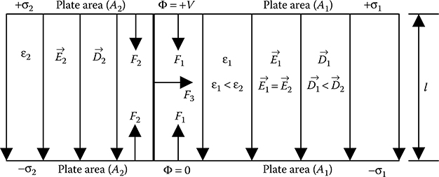
FIGURE 8.4
Two dielectric media in parallel between a parallel plate capacitor.
The forces acting on the two plates within the section of the capacitor containing dielectric 2 will be equal to F2 but will act in opposite directions. If A1 = A2, then F2 > F1 as ε2 > ε1. But the net force on the capacitor plates will always be zero due to the presence of equal and opposite forces on the plates.
But there will be mechanical force acting on the boundary between the two dielectric media, which according to Equation 8.21 is given by
where:
Ab = area of the dielectric–dielectric boundary
As stated earlier, in Equation 8.21, the mechanical pressure is considered to be acting from dielectric 1 to dielectric 2. As ε1 < ε2, F3, as per Equation 8.28, is negative, which indicates that the force F3 acts towards the dielectric of smaller permittivity, that is, from dielectric 2 to dielectric 1.
8.5.1 Electrostatic Pump
The mechanical force acting on the dielectric–dielectric boundary, as discussed in Section 8.5, can be demonstrated practically with the help of the arrangement shown in Figure 8.5, which is also known as electrostatic pump.

FIGURE 8.5
Demonstration of electrostatic pump.
If a charged parallel plate capacitor with air between the plates is partially submerged in a liquid dielectric, as shown in Figure 8.5, then the mechanical force on liquid–air boundary within the capacitor will act from the liquid dielectric to air, as the permittivity of air is smaller than the permittivity of liquid dielectric. Hence, this mechanical force will push the liquid up between the plates against the force of gravity. When the electrical force on the boundary and the weight of the liquid column between the capacitor plates become equal, then the upward movement of the liquid dielectric between the plates stops, and the surface of the liquid dielectric between the capacitor plates remains at a higher level than the surface of the liquid dielectric in the container.
As per Equation 8.28, the mechanical force on the liquid–air boundary acting towards air is
where:
lw = width of the plates normal to the plane of the paper
l = separation distance between the capacitor plates
V = potential difference between the capacitor plates
The gravitational force on the liquid column between the capacitor plates is
where:
h = height of the liquid column between the capacitor plates
ρ = density of the liquid dielectric
g = acceleration due to gravity
At equilibrium Fgravity = Fdielectric boundary, that is,
In the case of electrostatic pump, for a given liquid dielectric and for fixed dimensions of the capacitor, the height of the liquid column between the capacitor plates can be controlled by controlling the voltage applied across the plates.
PROBLEM 8.5
A parallel plate capacitor with air between the plates is submerged into transformer oil in a container in such a way that the top surface of transformer oil in the container is perpendicular to the capacitor plates. The potential difference between the capacitor plates is 15 kV and the separation distance between the plates is 6 mm. Density of transformer oil is 860 kg/m3. Calculate the height of the transformer oil column between the capacitor plates if εr for transformer oil = 2.1. What will be the height of the liquid column if transformer oil is replaced by water for which density is 1000 kg/m3 and εr is 80?
Solution:
Given: ρoil = 860 kg/m3, εr of oil = 2.1, V = 15 kV = 15 × 103 V and l = 6 mm = 6 × 10⁻³ m
Acceleration due to gravity (g) = 9.81 m/s2
Therefore,
If transformer is replaced by water, then ρwater = 1000 kg/m3, εr of water = 80.
Therefore
Objective Type Questions
1. Mechanical pressure acting on a charged conductor surface due to electrostatic field is equal to
a. Energy density of electrostatic field
b. Surface charge density on the conductor
c. Square of the surface charge density on the conductor
d. Square of electric flux density on the conductor
2. Mechanical pressure acting on a charged conductor surface due to electrostatic field is proportional to
a. Square of the electric potential of the conductor
b. Square of the electric field intensity on the conductor
c. Square of the surface charge density on the conductor
d. Square of the permittivity of the dielectric surrounding the conductor
3. Electric field intensity exactly on the conductor surface is equal to
a. Electric field intensity just off the conductor surface
b. Half of the electric field intensity just off the conductor surface
c. Twice the electric field intensity just off the conductor surface
d. Square of the electric field intensity just off the conductor surface
4. Mechanical pressure acting on the boundary between a dielectric and vacuum due to dielectric polarization is proportional to
a. The electric field intensity within the dielectric
b. The electric flux density within the dielectric
c. Square of the electric field intensity within the dielectric
d. Square of the electric flux density within the dielectric
5. Mechanical pressure on the boundary between two dielectric media due to electrostatic field acts on the boundary
a. Normally towards the dielectric having lower permittivity
b. Normally towards the dielectric having higher permittivity
c. Tangentially in the clockwise sense
d. Tangentially in the anti-clockwise sense
6. Within the surface film at the boundary between a dielectric and vacuum, the polarization vector
a. Remains constant
b. Varies linearly with distance
c. Varies from the finite value within the dielectric just off the boundary to infinity on the vacuum side of the boundary
d. Varies from the finite value within the dielectric just off the boundary to zero on the vacuum side of the boundary
7. From the known values of the dimensions of a parallel plate capacitor, the potential difference between the plates can be conveniently obtained from the measurement of
a. Surface charge density on the capacitor plates
b. Electric flux density between the capacitor plates
c. Polarization vector between the capacitor plates
d. Mechanical force acting on the capacitor plates
8. For a parallel plate capacitor having two dielectric media in series between the plates, mechanical pressure due to electric field is highest
a. On the plate having the dielectric of higher permittivity next to it
b. On the plate having the dielectric of lesser permittivity next to it
c. On the dielectric–dielectric boundary acting towards the dielectric of higher permittivity
d. On the dielectric–dielectric boundary acting towards the dielectric of lesser permittivity
9. A parallel plate capacitor with air between the plates is submerged into a liquid dielectric in a container in such a way that the top surface of the liquid in the container is perpendicular to the capacitor plates. Then the surface of the liquid dielectric column between the capacitor plates will be
a. At a higher level than the surface of the liquid within the container
b. At a lower level than the surface of the liquid within the container
c. At the same level as that of the surface of the liquid within the container
d. Parallel to the capacitor plates
Answers:
1) a;
2) c;
3) b;
4) c;
5) a;
6) d;
7) d;
8) b;
9) a