
7
Multi-Dielectric Configurations
ABSTRACT In multi-dielectric arrangements, electric field distribution is dependent on permittivities of the dielectrics along with the physical dimensions. Because dielectric strengths of the dielectric materials, which are the maximum electric field intensities that the dielectrics can withstand without failure, could be different, it is practically important to analyze electric field distribution in multi-dielectric arrangements that are commonly used in practice to ensure fail-safe operation. Electric field distribution in widely used real-life equipment such as parallel plate capacitor, coaxial cable and high-voltage bushing, which comprise multiple dielectric media, are analyzed in this chapter.
7.1 Introduction
Although single-dielectric arrangements are employed in real life, the number of such applications is small. In most of the cases, multiple dielectric media are used in various combinations between the electrodes or conductors. In such multi-dielectric arrangements, contrary to common belief, the location of maximum electric field intensity may not be just off the live conductor in all the cases. Thus, it becomes imperative that not only the magnitude but also the location of maximum electric field intensity should be determined accurately. This is to ensure that the maximum electric field intensity remains well below the dielectric strength of the material within which such maximum electric field intensity occurs. In the case of porous solid dielectric, the small pores are normally filled with air or another gaseous or liquid dielectric. Due to mismatch of the permittivity of the solid dielectric and the dielectric within the pores, electric field intensification may take place in the pores, which can also give rise to unwanted discharges within the equipment if appropriate measures are not taken to eliminate such field intensification. Thus, electric field analysis in multi-dielectric arrangements is not only important from the design viewpoint but also is significant from the viewpoint of life extension of equipment that has such multi-dielectric arrangement.
7.2 Parallel Plate Capacitor
Multiple dielectrics within a parallel plate capacitor can be either in series or in parallel between the plates. Such series and parallel dielectric arrangements need to be analyzed separately.
7.2.1 Dielectrics in Parallel between the Plates
A parallel plate capacitor with two dielectrics in parallel present between the plates is shown in Figure 7.1, such that the dielectric–dielectric boundary is perpendicular to the plates. If the separation distance between the plates is considered much smaller compared to the length and breadth of the plates, then the flux lines may be considered to be parallel to each other between the plates and also perpendicular to the plates within the dielectrics, neglecting the fringing of flux at the edges of the plates. Then along the paths of integration in both the dielectric media, as shown in Figure 7.1, the flux lines will be tangential. Hence, in dielectric 1,
and in dielectric 2,
where:
V is the potential difference between the plates of the capacitor
Applying Gauss’s law considering the Gaussian surface in dielectric 1, as shown in Figure 7.1,

FIGURE 7.1
Two dielectrics in parallel within a parallel plate capacitor.
Therefore, the capacitance between the plates comprising dielectric 1,
Again, applying Gauss’s law considering the Gaussian surface in dielectric 2, as shown in Figure 7.1,
Therefore, the capacitance between the plates comprising dielectric 2
Hence, the total capacitance of the parallel plate capacitor
7.2.2 Dielectrics in Series between the Plates
A parallel plate capacitor with two dielectrics in series present between the plates is shown in Figure 7.2, such that the dielectric–dielectric boundary is parallel to the plates. As seen in Section 7.2.1, if the separation distance between the plates is considered much smaller compared to the length and breadth of the plates, then the flux lines may be considered to be parallel to each other between the plates and also perpendicular to the plates as well as the dielectric–dielectric boundary within the capacitor, neglecting the fringing of flux at the edges of the plates.
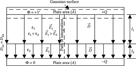
FIGURE 7.2
Two dielectrics in series within a parallel plate capacitor.
Applying Gauss’s law considering the Gaussian surface, as shown in Figure 7.2,
According to the boundary condition on the dielectric–dielectric boundary of Figure 7.2, D1n = D2n. Because the flux lines are perpendicular to the plates and hence to the dielectric–dielectric boundary, . In other words, electric flux density is the same in both the dielectric media.
Therefore, in dielectric 1, and in dielectric 2, .
Again, along the path of integration through the two dielectric media, as shown in Figure 7.2, the flux lines will be tangential.
Hence, in dielectric 1,
where:
V1 = potential difference across the dielectric 1
In dielectric 2,
where:
V2 = potential difference across the dielectric 2
If the potential difference between the plates of the capacitor is V, then
Let the capacitance of the parallel plate capacitor be C, the capacitance of the part comprising dielectric 1 be C1 and the capacitance of the part comprising dielectric 2 be C2.
Then from Equation 7.6,
and from Equation 7.7,
Hence, from Equation 7.8,
Further, from Equations 7.6 and 7.7,
It may be seen from Equation 7.10 that if the dielectric within a capacitor is gas (εr1≈1), then partial filling of the capacitor by a solid or liquid dielectric is actually detrimental to the capacitor. Because in that case, the electric field intensity in the gaseous dielectric will increase by a factor of εr2(εr2 > εr1) and may even exceed the dielectric strength of the gaseous dielectric resulting in discharge within the capacitor.
7.2.3 Void in Insulation
Voids could be present in insulation in many different shapes and due to several reasons. Voids could be in the form of a gas bubble in liquid insulation such as transformer oil, a gas bubble in moulded epoxy resin or a small gap in solid insulation, for example, gap formed due to delamination of pressboard insulation as a result of aging. Such voids are typically filled with air at a pressure slightly less than atmospheric pressure. A void in an insulation is schematically shown in Figure 7.3. Considering the void dimensions to be small in comparison to the insulation surrounding it, it may be reasonably argued that the presence or absence of the void will not alter electric flux density at the location of the void. Then according to the discussions of Section 7.2.2 and Equation 7.10,

FIGURE 7.3
Void in insulating medium.
Thus, from Equation 7.11, it is evident that electric field intensity within the void will be higher than that in the insulating medium. On the other hand, the dielectric strength of air filling the void will be lower than that of the insulating medium. Consequently, there is every possibility that electric field intensity in the void may be in excess of the dielectric strength of air at the pressure and temperature within the void. This could result in discharge within the void. But there will be no discharge within the insulating medium around the void, as electric field intensity there is lower and the dielectric strength of the insulation is higher. Such localized discharge within the void is called partial discharge (PD) and is highly detrimental to high voltage equipment as PD reduces the life of the equipment significantly.
7.2.4 Impregnation of Porous Solid Insulation
Solid insulations that are porous in nature, for example, paper or pressboard, are very commonly used in high-voltage equipment. In such cases, the solid insulation is mainly cellulose, whereas the gas in the pores is air. The relative permittivity of cellulose insulation is of the order of 3 ~ 4 and the dielectric strength of cellulose is about 16 kV/mm. On the other hand, relative permit-tivity of air is ~1 and the dielectric strength of air is 3 kV/mm. In order that the solid insulation does not fail due to discharges within the pores, electric field intensity within the solid insulation has to be kept around 9 ~ 12 kV/mm, so that electric field intensity in the pores remains below 3 kV/mm. But in that case the capacity of the paper insulation is not utilized to the full extent. Therefore, in practice, such porous solid insulation is always impregnated with a suitable liquid dielectric. Due to impregnation, the pores in the solid insulation will be filled by the liquid insulation, which will have higher dielectric strength compared to air. But here it is important to note that the relative permittivity of the liquid dielectric used for impregnation must be close to the relative permittivity of the solid insulation being impregnated. Otherwise, there will be again a mismatch of the electric field intensity values within the liquid and solid dielectrics and the full benefit of impregnation could not be obtained.
7.3 Co-Axial Cylindrical Configurations
Co-axial multi-dielectric arrangements, which are commonly used in power engineering, are cables and bushings. A single-core cable having three different dielectrics in between the core and the earthed metallic screen is shown in Figure 7.4. Bushings are special components used in high-voltage system when a high-voltage conductor has to pass through an earthed barrier, for example, earthed tank of a transformer or a wall and so on. Figure 7.5 shows a solid-type oil-impregnated paper bushing used in transformers typically for voltage ratings below 90 kV. If a cross section is taken at AA′, as shown in Figure 7.5, then the cross-sectional view will be same as that shown in Figure 7.4. Hence, the radial field distribution at the critical zone AA′, where the distance between the high-voltage conductor and the earthed metallic flange is minimum, could be determined with reasonable degree of accuracy using the same analysis as in the case of cables.

FIGURE 7.4
A single-core cable having three different dielectric media.

FIGURE 7.5
Solid-type oil-impregnated paper bushing used in transformers.
Electric field in the co-axial arrangement of Figure 7.4 is analyzed assuming that electric field does not vary along the length of the cylinder normal to the plane of the paper. For cables this assumption is perfectly valid, whereas for bushings, it is not valid as such, but the nature of radial field distribution thus obtained gives a fair idea about the field concentration in the critical zone AA′ that may cause eventual failure of a bushing.
Let the charge per unit length on the inner conductor be q. Then for the Gaussian surface, as shown in Figure 7.4, electric flux density at a radial distance of x can be obtained from the surface area of a cylinder of radius x and axial length unity, that is,
Hence, electric field intensity at any radius x is given by
where:
εx is the permittivity of the dielectric at the radial distance x
Then the potential difference V between the high-voltage conductor and the earthed enclosure could be obtained from the line integral of electric field intensity. Considering the path of integral from D to A,
But the integral of Equation 7.13 needs to be evaluated section-wise where the permittivity remains constant. Thus,
In Equation 7.14, it may be seen that the expression within the parenthesis on the right-hand side is a constant for a given multi-dielectric arrangement. Hence, the charge per unit length on the inner conductor can be expressed in terms of the potential difference and the computed constant of Equation 7.14 as follows:
The capacitance per unit length of the multi-dielectric arrangement is
Electric field intensity at any radius x is then given by
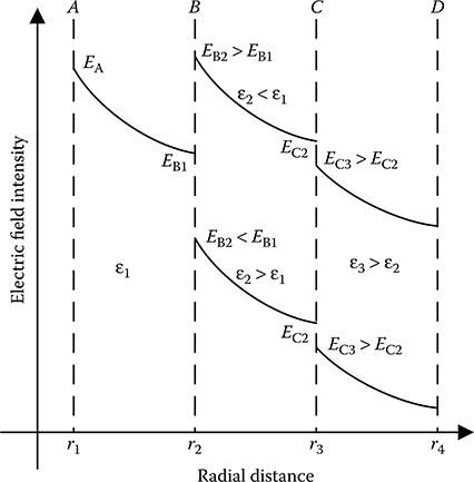
FIGURE 7.6
Radial variation of electric field intensity in co-axial multi-dielectric arrangement.
From Equation 7.17, it is clear that electric field intensity varies inversely with radial distance within each section of the arrangement comprising one particular dielectric. Thus, the variation of electric field intensity can be plotted with radial distance, as shown in Figure 7.6. From Figure 7.6, it may be seen that there is a discontinuity in electric field intensity at the boundary between two different dielectric media. The value of electric field intensity may increase or decrease at the boundary depending on the relative values of the permittivity of the two dielectric media at the boundary. Thus, for a multi-dielectric arrangement, as shown in Figure 7.4, it cannot be stated that the maximum value of electric field intensity will occur just off the surface of the inner conductor in all the cases. On the contrary, it has to be ascertained case by case considering the physical dimensions and the dielectric arrangement.
PROBLEM 7.1
A single-core, lead sheathed cable joint has a conductor of 10 mm diameter and two layers of different insulating materials, each 10 mm thick. The relative permittivities are 3 and 2.5 for inner and outer dielectrics, respectively. Calculate the potential gradient just off the conductor surface, when the potential difference between the conductor and lead sheath is 33 kVrms.
Solution:
Given: εr1 = 3 and εr2 = 2.5, r1 = (10/2) = 5 mm, r2 = 5 + 10 = 15 mm and r3 = 15 + 10 = 25 mm.
Therefore, according to Equation 7.15,
Hence, potential gradient just off the conductor surface
PROBLEM 7.2
A transformer bushing for 36 kVrms consists of the following:
Component |
Outside |
Diameter |
Copper rod |
4 cm |
|
Treated paper |
5 cm |
3 |
Transformer oil |
10 cm |
2.1 |
Porcelain |
15 cm |
5 |
Find the magnitudes and locations of maximum and minimum electric field intensities within the bushing.
Solution:
This problem is solved in accordance with Figure 7.4 and Equations 7.15 and 7.17.
Given: εr1 = 3 and εr2 = 2.1 and εr3 = 5, r1 = 2 cm, r2 = 2.5 cm, r3 = 5 cm and r4 = 7.5 cm.
Therefore, according to Equation 7.15,
Therefore, according to Figure 7.4, within paper insulation just off the conductor surface
At the paper–oil boundary, on the paper side
At the paper–oil boundary, on the oil side
At the oil–porcelain boundary, on the oil side
At the oil–porcelain boundary, on porcelain side
Within porcelain just off the Earth surface
Therefore, the maximum electric field intensity is 14.12 kVrms/cm at the oil side of the oil–paper boundary, and the minimum electric field intensity is 1.98 kVrms/cm within porcelain just off the Earth surface.
PROBLEM 7.3
A conductor 2.8 cm in diameter is passed centrally through a porcelain bushing (εr = 5) having internal and external diameters of 3 and 9 cm, respectively. The potential difference between the conductor and the earthed metallic flange around the porcelain is 12 kVrms. Determine whether or not partial discharges will be present in the airspace around the conductor. Also, find the electric stress just off the conductor surface, if the airspace is filled with transformer oil (εr = 2.1).
Solution:
The arrangement as per the statement of the problem is shown in Figure 7.7. With reference to Figure 7.7, the given quantities are as follows:
εr2 = 5, r1 = 1.4 cm, r2 = 1.5 cm and r3 = 4.5 cm
Case I: When the small space between the copper rod and porcelain cover is filled with air. Then εr1 = 1. Therefore, according to Equation 7.15, in this case
Within this airspace, the maximum electric field intensity will occur just off the conductor surface and will be
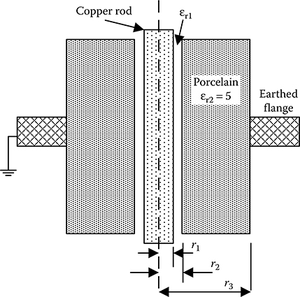
FIGURE 7.7
Pertaining to Problem 7.3.
Breakdown strength of air is 30 kVp/cm or 21.21 kVrms/cm at standard temperature and pressure (STP). Therefore, partial discharges will be present in the airspace.
Case II: When the small space between the copper rod and porcelain cover is filled with transformer oil instead of air. Then εr1 = 2.1. Therefore, according to Equation 7.15, in this case
Then the maximum electric field intensity just off the conductor surface is
It may be seen that filling up the small space by transformer oil brings down the electric field intensity considerably. Moreover, transformer oil has higher breakdown strength than air. Therefore, partial discharges will not occur in the small gap.
This problem brings out an important aspect of transformer bushing design. Because copper and porcelain are both solid, it is very difficult to get a perfect contact between them. Therefore, intentionally a small gap is kept between these two for easy operation. But if this small space is kept filled with air then partial discharge is inevitable, which is undesirable. Hence, the solid-type bushings are always so designed that this small space is filled with transformer oil instead of air.
Objective Type Questions
1. An air-filled parallel plate capacitor is charged and then the voltage source is disconnected from the plates. Now half of the airspace is filled with transformer oil, so that the oil-filled half is in series with air-filled half. Then
a. The potential difference between the plates will increase
b. The potential difference between the plates will decrease
c. The energy stored in the capacitor will increase
d. The energy stored in the capacitor will decrease
2. The potential difference between the plates of an air-filled parallel plate capacitor is kept constant by a DC voltage source. Now half of the airspace is filled with pressboard (εr), so that the pressboard-filled half is in series with air-filled half. Then the electric field intensity in air will be
a. times the electric field intensity in pressboard
b. εr times the electric field intensity in pressboard
c. 1/εr times the electric field intensity in pressboard
d. times the electric field intensity in pressboard
3. An air-filled parallel plate capacitor is charged and then the voltage source is disconnected from the plates. Now a solid dielectric slab (εr = 4) of thickness equal to the separation distance between the plates is inserted half way into the capacitor such that the air-filled part is in parallel with the solid-filled part. Then
a. The potential difference between the plates will increase
b. The potential difference between the plates will decrease
c. The energy stored in the capacitor will increase
d. The energy stored in the capacitor will decrease
4. If a small void is present in a solid insulation, then the electric field intensity within void is
a. Higher than that in the solid insulation
b. Lower than that in the solid insulation
c. Equal to that in the solid insulation
d. Zero
5. If a small void is present in a solid insulation, then there is very high probability that
a. Complete breakdown of the insulation system will take place
b. Breakdown of solid insulation will take place around the void
c. Breakdown of gaseous insulation will take place within the void
d. No breakdown will take place
6. Impregnation of porous solid insulation is done using a liquid dielectric for which
a. Dielectric strength should be same as that of the solid insulation
b. Volume resistivity should be same as that of the solid insulation
c. Dielectric dissipation factor should be same as that of the solid insulation
d. Permittivity should be same as that of the solid insulation
7. For a single-core screened cable with three layers of different dielectric materials arranged in co-axial form, electric field intensity within the second layer of dielectric is maximum
a. At the boundary between dielectric 1 and dielectric 2
b. At the boundary between dielectric 2 and dielectric 3
c. In the middle of dielectric 2
d. None of the above
Answers:
1) b;
2) b;
3) b;
4) a;
5) c;
6) d;
7) a