
Setup
In order to use all this gear and have an organized project mixer, we must first set up Nuendo to deal with all the various signal paths. Let’s start with the VST Connections because that is where all of the analog IO settings are made.
VST Outputs
Since we are using an analog summing device, we need to create outputs that will feed each channel on the summer. We will match the channel configuration of the VST Output to match the summer’s inputs. Each output can be given a name. Descriptive names will aid in making quick connections in the mixer later.
In addition to the eight outputs for the summer box, another stereo output will be created as a final output for the finished mix once it has been recorded back into Nuendo. This output will be designated the Main Mix and as such will be routed to the Control Room mixer by default.
Figure 16.1 shows what the VST Output tab looks like.
Note The DIG MIX or digital mix bus is set to Not Connected. This is on purpose. Even though it is not connected to an output channel of the converters, it will still be routed to the Control Room since it is the Main Mix. Once in the Control Room mixer, it can be routed to monitor speaker outputs as set in the Control Room configuration.

External FX
External FX allows Nuendo to use external hardware as inserts within the Nuendo mixer. While we certainly will use some of the outboard gear for the outputs that feed the summer box, we will use certain pieces of gear inside the Nuendo mixer as inserts:
![]()
Even though the lead vocal will have its own channel in the summer, it makes sense to insert the compressor inside the Nuendo mixer where all the level changes will take place with automation. This way, the compressor’s action will be constant even as the channel’s level changes. If we used the compressor inserted on the summer box channel, any changes made in level of the lead vocal would drive the compressor differently.
So we will create two external inserts: one mono for the LA-2A and another stereo one for the 1081s. The External FX tab is shown in Figure 16.2.

It will be possible to determine the latency that these routings create once you have set them up. The plug-in GUI has a ping test to measure the delay induced by the system and converters.
Ping Test for External FX Latency
Once you have a project set up, insert the External FX into a channel. Patch the analog output of the audio interface assigned to the External FX to the actual hardware input of the device. Patch the output of the unit back into the assigned audio interface input. Ensure that the device is in bypass or at least is not adding any delay of its own. For example, if the unit was a delay, it should be set to pass the dry signal only so as not to confuse the measuring process.
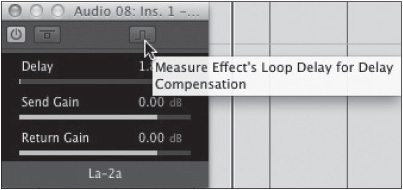
From the plug-in GUI, press the ping button and notice the number that pops up in the Delay field. This is the measured delay of the round trip for the signal and will be used to compensate for the latency. (See Figure 16.3.)
Figure 16.3 External FX plug-in GUI.
Inputs
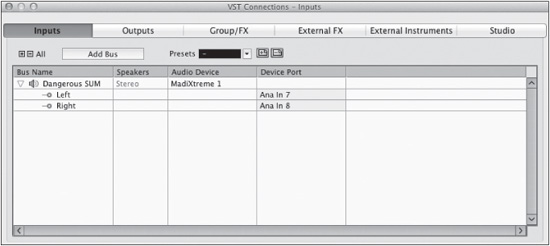
The only input that needs to be set up is for the summing device so that it may be recorded back into Nuendo for the final mix. There may be other inputs for various mic preamps and such because the studio is configured, but the summing device needs its own input here as well. (See Figure 16.4.)
Control Room
Let’s take a brief look at the Control Room setup. Depending on the studio’s configuration, you might have several sets of speakers set up here along with headphone sends, talkback, etc. One item that needs to be added is a monitor source for the summing box.
From the Add Channel menu, choose Add Monitor Source and choose the input for the summing device. This will add that input as a monitor source in the Control Room mixer so that while mixing, you can monitor the output of the summing device right from Nuendo. (See Figure 16.5.)
Figure 16.5 Add Monitor Source.

Now the Control Room mixer should list the summing box as a monitor source. (See Figure 16.6.)
When Dangerous SUM is selected, the Control Room output will route the summing box inputs to the selected monitor output. By default, the DIG MIX is available as a monitor source since it is set as the Main Mix in VST Connections.
Note I have a metering plug-in inserted into the Control Room channel so that I can quickly see levels and spectrum of any signal passing through the Control Room.
Subgrouping (Group Channels)
Subgrouping is the main method of paring down this many channels into a manageable mix. In thinking ahead to the mix, we can plan many of the subgroups needed. For each subgroup, a group channel will be created. If more subgroups are needed, they can always be added later. Let’s set up as many as we can in advance:
1. Drums—stereo
2. Drum parallel compression—stereo
Figure 16.6 Control Room mixer with monitor source.

3. Bass—mono
4. Main rhythm guitars—stereo
5. Chorus line guitars—stereo
6. Percussion—stereo
7. Strings—stereo
8. Background vocals—stereo
You can quickly set up a bunch of group channels right in the VST Connections window. This works in the same way as in the project window. Press the Add Group button and choose the number and configuration of group channels you desire. (See Figure 16.7.)

FX Channels
Let’s configure FX channels for this mix. Again, you can always add more later, but it’s nice to start out with many of the ones you plan on using right from the start:
1. Plate reverb
2. Short mono delay
3. Stereo tap delay
4. Chorus
5. Room reverb
6. Harmonic exciter
7. Long echo
8. Short stereo slap delay
From the VST Group/FX tab, press the Add FX button and choose the plug-in and channel configuration for each FX. (See Figure 16.8.)
Figure 16.8 Add FX Channel Track.

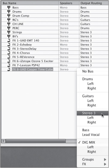
You can even assign all the group and FX channels to specific outputs right here in the VST Connections window. This can sometimes be easier and quicker to do while configuring the mix. Notice that all newly created channels will have their output default to whatever is set as the Main Mix in the outputs tab. All the FX returns have been routed to Stereo 3. (See Figure 16.9.)
Figure 16.9 Routing FX channels.
Note Any channel can be saved as a track preset, giving you quick access to its configuration and settings in other projects. Groups of channels can be exported as a Track Archive and then imported together into other projects for quicker configuration of many channels at once.
This about does it for preparation. Next, all the audio tracks need to be routed to take advantage of all the signal paths that have been created.