
VST Connections
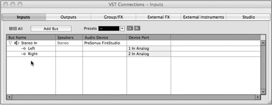
Open the VST Connections window from the Devices menu (F4). (See Figure 2.6.) This is where all of the audio connections will be made into and out of Nuendo. This window maps your audio interface’s physical inputs and outputs to Nuendo’s virtual inputs and outputs. There are many possibilities here, including simple inputs and outputs of Nuendo’s mixer, but also more complex routings such as external FX inserts, external MIDI instruments, Control Room monitoring, and headphone channels.
Figure 2.6 VST Connections window.
Using a large multi-channel audio interface, many intricate connections can be made. All of these can be saved as presets that can be called up in any project. This flexibility in routing and the quickness with which it can be implemented are among the most powerful aspects of Nuendo. You may switch between a 5.1 film mixing workstation directly to a multi-track band recording setup in a matter of moments.
VST Inputs
The VST Inputs tab contains the current list of inputs available to Nuendo. By default, there is a stereo input already created. Understand that this is a virtual layer between your audio interface and the Nuendo application. Many inputs can be created here, more than your interface is capable of or less than all the available inputs. The idea is that you only create the number and types of inputs that you need.
Inputs have several attributes:
![]() Channel width—Each input can have its own channel width starting with mono and continuing with stereo, 5.1, and on up to 10.2 surround.
Channel width—Each input can have its own channel width starting with mono and continuing with stereo, 5.1, and on up to 10.2 surround.
![]() Sharing of physical inputs—Inputs can share physical interface inputs as much as you desire. For example, a mono input can use the first channel on your interface while a 5.1 input can use that same interface channel (1) plus 5 more (2-6) to make up a single 5.1 source.
Sharing of physical inputs—Inputs can share physical interface inputs as much as you desire. For example, a mono input can use the first channel on your interface while a 5.1 input can use that same interface channel (1) plus 5 more (2-6) to make up a single 5.1 source.
![]() Child buses—Multi-channel inputs automatically generate mono “child” buses. Each channel of a multi-channel input is available as a mono input within Nuendo. You can also create multi-channel child buses of surround buses. For example, you can create a stereo child bus for a 5.1 surround bus out of the front left and right channels.
Child buses—Multi-channel inputs automatically generate mono “child” buses. Each channel of a multi-channel input is available as a mono input within Nuendo. You can also create multi-channel child buses of surround buses. For example, you can create a stereo child bus for a 5.1 surround bus out of the front left and right channels.
![]() Can be “Not Connected”—Input buses can be set as Not Connected. This can happen when a project from a larger system is opened on a system that does not have the physical inputs available to match all the VST Inputs. These input buses can remain in the project, and when it is reopened in the larger system, they will connect back to their physical inputs on that system.
Can be “Not Connected”—Input buses can be set as Not Connected. This can happen when a project from a larger system is opened on a system that does not have the physical inputs available to match all the VST Inputs. These input buses can remain in the project, and when it is reopened in the larger system, they will connect back to their physical inputs on that system.
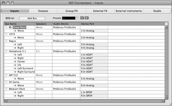
Go through your studio and figure out what will be connected to the inputs of your audio interface. This is a highly customizable part of Nuendo and will be different for each studio and setup. In my studio, I name the inputs by the microphone preamp that is normally connected to that input. This helps me keep track of which preamp was used on a particular track. If you are using a patch bay, this layout can change every session. You can change the labels of each input used in a project as it will be saved with the project file, preserving your routing information. (See Figure 2.7.)
Figure 2.7 A well-populated VST Inputs tab.
In order to create a VST Input, follow these steps:
1. Press the Add Bus button at the top of the window. The Add Input Bus dialog box opens. (See Figure 2.8.)
Figure 2.8 The Add Input Bus dialog box.

2. From the configuration menu, choose the channel width and format. There are a variety of channel formats up to 12 channels wide.
3. If you wish to create more than one of the same type of bus, increment the count.
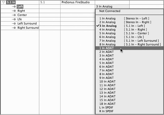
4. Device ports will be assigned automatically to each channel of the bus, usually incrementing up from the last used port. You may change these assignments by clicking on the device port name and choosing another port from the menu. (See Figure 2.9.)
Figure 2.9 Device port assignment menu.
5. Name the input bus by clicking on the Bus Name and typing in your name. (See Figure 2.10.)
6. Continue adding buses until all the inputs you will use have been set up.

Tip You can assign device ports to more than one channel of any VST connection. To do this, hold the Shift key while selecting the first device port of any VST connection. For that bus, device ports will be assigned incrementally starting with the port you selected for all channels in that bus. If you Shift+select more than one bus and use this technique, device ports will be assigned incrementally for all selected buses at once. This can make setting up a complex multi-channel environment much quicker.
Once a set of inputs has been created and labeled, you can save it as a preset using the Presets tools at the top of the window. (See Figure 2.11.)
Note By adding a preset and typing in the exact name of an existing preset, you can modify or update that preset with the current settings. This is true for all presets in VST Connections. Having a good set of presets that covers the basic ways you work every day can save valuable time setting up various types of sessions in Nuendo.
VST Outputs
The VST Outputs tab functions in many of the same ways as the Inputs tab. You can create output buses in the same way, assigning various device ports to the channels in each bus. You can name each bus and save the entire list of buses as a preset in the same manner as for input buses.
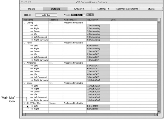
For simple stereo projects, only one stereo output bus might be needed. If you use an external analog mixing desk, individual mono output buses can be used to feed each channel of a mixer. For a film dubbing project, multiple surround output buses may be needed to feed a stem recorder. (See Figure 2.12.)

Each one of these possible scenarios can be saved as a preset and called up whenever it’s needed. That’s the routing flexibility that Nuendo provides. The presets menu comes populated with various configurations to start. You can modify these to meet your needs and save them as new presets.
Output Child Buses
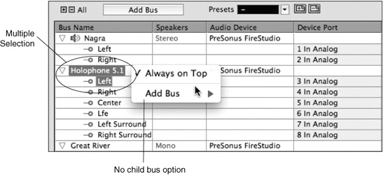
In complex surround sound mixing, there is a need to have specific types of child buses available for each surround bus. To create specific child buses for an output bus, right-click (Windows) or Control+click (Mac) on an output bus’s name and choose an option from the Add Child Bus menu (see Figure 2.13). All possible formats for that size output bus will be displayed for you to choose from.
Figure 2.13 Add Child Bus menu.

Caution In order to create a child bus, you must select the name of the bus only. If any other channel within that bus is also selected, the child bus option will not appear in the contextual menu. (See Figure 2.14.)
Main Mix Designation
Notice in the preceding example that there is a speaker icon next to the ST Ref Mix output bus. This icon indicates that the ST Ref Mix bus is the Main Mix. The Main Mix designation has to do with monitoring through Nuendo’s Control Room features covered later in this chapter. Since Nuendo can have multiple output buses, one of these must be designated the Main Mix for monitoring purposes through the Control Room mixer.
Figure 2.14 Multiple selection will not allow child bus creation.
In order to set any output bus as the Main Mix, right-click (Windows) or Control+click (Mac) on the name of the bus to access the contextual menu. Check the Set as Main Mix option (Figure 2.15) and notice the speaker icon next to the bus name.
Figure 2.15 Set as Main Mix option.

Output Bus Not Connected
It is possible and common to have output buses not connected directly to any device port. Instead of monitoring the output buses directly, Nuendo can route these signals through the Control Room mixer, which is connected to the device ports for monitoring. Using the Control Room features, you can monitor various points in the mixer’s signal chain through dedicated monitor outputs. Final mixdown files can still be created from any output bus whether it is connected to a device port or not.
Tip VST output buses should only be connected to device ports when the signals need to be fed into an external console, when they need to be recorded by an external device or routed to a broadcast feed, or if the Control Room is not active for monitoring.
Click Option
The last column in Outputs is the Click option. The internal click generator in Nuendo can be routed in multiple ways, one of which is by checking the Click option for any output bus to which you wish to route the internal click sounds. This routing is separate from the Control Room where you can also route the click to various outputs. The Control Room does not have to be active for the Click option in Outputs to function.
You may only activate Click on the entire output bus, not child buses or mono channels by themselves.
Group/FX
The Group/FX tab does not pertain to actual inputs or outputs from Nuendo. Rather it deals with internal mixer routing options within Nuendo. This will be discussed in great detail in Part IV, “Mixing.” Group and FX channels that are a part of the active project are displayed here. It is also possible to create new group and FX channels in this tab and save presets of multiple group and FX channels.
External FX
The External FX tab allows the creation of outputs and inputs that can be routed to external processing devices such as compressors, equalizers, and reverb units that you wish to use inside Nuendo’s mixer. Once created, these external FX can be inserted just like plug-ins on any audio channel in the mixer.
Audio will pass out of the assigned outputs to your external device and then return through the assigned inputs back into Nuendo’s mixer. You can mix plug-ins with external FX on the same channel if you wish. In this way, all of your favorite analog equipment can be used inside the digital mixer just like any other plug-in processing.
If the external device is MIDI-controllable, a MIDI device can be associated with the external FX so that when it is inserted, its MIDI device panel will open just like a plug-in GUI. This allows you to remote control the device and save the parameters within the Nuendo project for later recall.
To create external FX, follow these steps:
1. Press the Add External FX button. The Add External FX dialog box will open.
2. Click in the Name field and enter the name of the device.
3. Choose Send Configuration. How many inputs does the device have?
4. Choose the Return Configuration. This may be different than the send. For example, many reverb units have a mono input but a stereo output. There is no need to waste device ports on unused channels.
5. If the device is MIDI-controllable and you have created a MIDI device for it in Nuendo, you can attach that to the external FX by pressing the Associate MIDI Device button and choosing the appropriate MIDI device.
6. Click OK and the device will appear in the list.
7. Assign device ports to the inputs and outputs that will be connected to the external device. (See Figure 2.16.)
Figure 2.16 Add External FX dialog box.

If this is an external effect that you plan on using often, add it as a Favorite so that it may be recalled in other projects easily. This is similar to the presets in the Inputs and Outputs tabs. To add an external effect as a favorite, right-click (Windows) or Control+click (Mac) on its name and choose Add to Favorites from the menu. Now this device will be available from the Favorites button in any active project.
Note The option to Check User Delay pertains to mixer delay compensation. This topic will be covered in detail in Part IV. Delay compensation deals with processing delays caused by plug-ins and latency in the case of external FX. The user delay is the amount of latency associated with this device. This can be manually changed to get optimal performance from delay compensation in the mixer. Nuendo can also “ping” the device to check for the amount of delay it causes.
External Instruments
External instruments allow you to use MIDI keyboards and other external MIDI devices, such as an Aka MPC workstation, in Nuendo as if they were a part of the program similar to a VSTi virtual instrument. Much like external FX, external instruments have a MIDI device associated with them but only have audio inputs as a part of their configuration. Each external instrument can have multiple mono and stereo inputs associated with it. In order to create an external instrument, follow these steps:
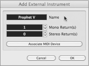
1. In the External Instruments tab, press the Add External Instrument button. The Add External Instrument dialog box will open.
2. Click in the Name field and enter the name of the new instrument.
3. Choose the number of mono and stereo inputs the instrument will have in Nuendo.
4. If you have created a MIDI device for this instrument, press the Associate MIDI Device button and add it to the instrument. (See Figure 2.17.)
Figure 2.17 Add External Instrument dialog box.
The newly created instrument can be added to a project just like any other VSTi. You will be able to create MIDI tracks for this instrument and automatically have them routed to the device and have the resulting sounds come into the mixer. More information on external instruments, VSTi’s and MIDI can be found in Part II, “Recording,” and in the “MIDI Connections” section of this chapter.
Device Port Sharing
Some VST connections can share device ports with others. For example, you could create a stereo input bus that uses device ports 1 and 2. You could then create another mono input bus that also uses device port 1 and so on. This can be useful for naming various inputs or having alternate input bus names for the same device ports. The same is true of output buses. Just be sure to keep track of any VST connections that share device ports because this can be a source of confusion.
External FX and external instruments, however, cannot share either input or output device ports with any other VST connection. If you have device ports used by an external effect or instrument and you wish to use it for something else, you must either remove the external device from the VST Connections or set their device ports to Not Connected in order to free up the port.
Device ports that have been assigned to exclusive VST connections are denoted in the device port list in red. If you select this port for another VST connection, it will break the current connection. In Figure 2.18 you can see that In ADAT 1 and 2 are exclusively being used by return buses for an external effect. Also, you can see that 6 In Analog is being shared by the Great River and the Holophone’s LFE input.
Figure 2.18 Device Port sharing.

Control Room and Studio
Nuendo’s Control Room features are some of the most valuable in day-to-day use of the software in a real studio environment. The ability to listen to external sources, route headphones and talkback signals to various outputs, manipulate speaker configurations and calibration, all within the software, is powerful and adds a great deal of functionality to Nuendo.
The Control Room is scalable in its configuration. You can use as many or as few of the features as you need. Just like the other tabs in VST Connections, you add only the channels you need and nothing more. To enable the Control Room, go to the Studio tab in VST Connections and enable the power button for Control Room as seen in Figure 2.19.
Control Room Overview
Initially, the Control Room will contain one monitor channel. You have to have at least one monitor channel for Control Room to function. The quickest way to get a handle on what the Control Room is capable of is to open the Control Room Overview from the Devices menu. This window is used to visually represent all of the Control Room features and the current configuration. (See Figure 2.20.) Highlighted items are active in the current configuration while grayed-out items are available to add but not active.
Figure 2.19 Studio Tab in VST Connections.

Figure 2.20 Control Room Overview.

Following is a list of all the possible Control Room channels and functions available:
![]() Monitor. A monitor channel is connected to a set of speakers. Consider them speaker channels. All formats from mono to eight-channel surround are supported. Up to four monitor channels may be created. They can share outputs if necessary and do not need to be the same channel configuration.
Monitor. A monitor channel is connected to a set of speakers. Consider them speaker channels. All formats from mono to eight-channel surround are supported. Up to four monitor channels may be created. They can share outputs if necessary and do not need to be the same channel configuration.
![]() Headphones. One dedicated stereo headphone channel is available. This should not be confused with the Studio channels that are designed to feed headphones or monitors for musicians and performers in the studio while recording. This headphone channel is primarily designed for the engineer to monitor sounds in the Control Room, including the listen bus.
Headphones. One dedicated stereo headphone channel is available. This should not be confused with the Studio channels that are designed to feed headphones or monitors for musicians and performers in the studio while recording. This headphone channel is primarily designed for the engineer to monitor sounds in the Control Room, including the listen bus.
![]() Studio. The Studio channels are for performers to hear themselves and the rest of the mix during recording. There are four stereo Studio channels available. I use four stereo Studios to feed an eight-channel headphone system with great results.
Studio. The Studio channels are for performers to hear themselves and the rest of the mix during recording. There are four stereo Studio channels available. I use four stereo Studios to feed an eight-channel headphone system with great results.
![]() External Inputs. External input channels allow you to monitor other sources outside Nuendo. This is handy for listening to CD and DVD players or for playback of multi-channel audio for cinematic presentation. There are four external inputs available in formats up to eight channels wide.
External Inputs. External input channels allow you to monitor other sources outside Nuendo. This is handy for listening to CD and DVD players or for playback of multi-channel audio for cinematic presentation. There are four external inputs available in formats up to eight channels wide.
![]() Talkback. One talkback channel can be created, which allows the engineer to communicate with performers in the studio and provides useful functionality such as dimming the main speakers when the talkback is on and auto-off during recording.
Talkback. One talkback channel can be created, which allows the engineer to communicate with performers in the studio and provides useful functionality such as dimming the main speakers when the talkback is on and auto-off during recording.
![]() Monitor Sources. Every VST Input and Output can be made into a Monitor Source. These Monitor Sources can then be selected in the Control Room Mixer and heard through the selected monitor channel. The VST Output designated the Main Mix is the default monitor source.
Monitor Sources. Every VST Input and Output can be made into a Monitor Source. These Monitor Sources can then be selected in the Control Room Mixer and heard through the selected monitor channel. The VST Output designated the Main Mix is the default monitor source.
You can add various channels to the Control Room by using the Add Channel button found in the Studio tab. Choose the type of channel you wish to add, and a dialog box will open that allows you to name the channel and choose a channel configuration.
Once you have added all your desired channels, you can assign device ports to each one just like other VST connections. This is where things can get a bit confusing as many VST connections can share device ports.
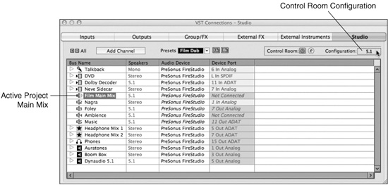
Main Mix Control Room Configuration
The Control Room has an overall channel width configuration. This is determined by the channel configuration of the Main Mix of the active project. The current configuration is displayed at the top right of the Studio tab in VST Connections. Figure 2.21 shows a well-populated Control Room preset for film dubbing. Notice the configuration of the Control Room matches that of the Monitor Source Film Main Mix.
Device Port Sharing in Control Room
All channels in the Control Room, with the exception of monitors, use exclusive device ports. This means that once you assign a particular input or output port to a Control Room channel, it will not be available to any other VST connection.
For monitor channels, there is a preference to choose whether or not they use exclusive device ports. It can be helpful for surround speaker arrays to share device ports between monitor channels so that you can create a stereo monitor pair from the main left and right speakers in a surround setup. This makes it possible to change from a surround system to a stereo playback system using the same speakers, including downmixing. This is similar to the child bus concept for VST Outputs.
Figure 2.21 Control Room configured for film mixing.
To create a stereo monitor using shared device ports from a surround speaker system, follow these steps:
1. Create a 5.1 monitor channel and assign it to device ports that are connected to the corresponding speakers.
2. Create another stereo monitor channel and assign it to the same device ports as the main left and right speakers of the surround monitor channel.
You can now switch easily from surround to stereo monitoring using the same speaker system. Operation of the Control Room Mixer is covered in the next section.
Caution Trouble can arise is you inadvertently assign a VST Output bus (especially the Main Mix) to the same device ports as a monitor channel. This results in both signals being combined on the shared device port. If the Main Mix bus is assigned to the same device ports as the current monitor channel, a doubling in volume of the sound will be heard at the output of the audio interface, potentially causing harm to speaker systems and your hearing! Also, none of this clipping will be visible in Nuendo’s meters since it is taking place at the audio interface and not inside Nuendo.
To avoid this possibility, go to Preferences>VST>Control Room and check the option for Exclusive Device Ports for Monitor Channels.
Tip Create a preset for your Control Room Setup in the Studio tab. This makes all of the complex settings in Control Room recallable. You might create two presets: a simple setup for stereo music recording with more Studio channels and a more complex surround setup for film mixing. Control Room channels take up system resources, so only use the channels that you need. Flexibility is the idea here.
Control Room Mixer
The Control Room Mixer allows you to adjust every channel that you have created in the Studio tab of VST Connections. It expands or contracts depending on the type and number of Studio channels you have made. Just like the project mixer, portions of the GUI can be hidden from view if not being used so as to not take up any more screen space than necessary. Figure 2.22 labels all the controls available in the fully expanded mixer with at least one of each type of channel shown. The major controls are discussed in detail with examples of how they might be used.
Figure 2.22 Control Room mixer.

1. Input Gain and Polarity for External Inputs—Each external input could be coming from various devices having differing operating levels. This gain setting is recalled with each specific external input and can be used to level match their signals to a comparable level of your mix, allowing more accurate A/B comparisons. Polarity can be reversed as well.
2. Inserts for External Inputs—The Control Room Mixer allows for inserts on each channel. These inserts are recalled for each specific external input. Metering and analysis plug-ins are a common use for these inserts. An external input with wildly fluctuating levels might need a compressor or limiter as well.
3. Input Selector—These buttons choose the inputs for all the Control Room channels.
4. External Input Selector—This allows you to choose from as many as six external inputs of various channel widths. That’s more than most professional analog consoles of yesterday ever had, never mind surround capable!
5. Monitor Source Select—This lets you choose from any VST Input or Output bus in Nuendo that you have defined as a Monitor Source. The Main Mix is the default source, but you can add as many other buses as you wish. This is especially handy in film mixing where your mixdown is actually many outputs that can be of various channel widths going to a stem recorder and then combined into the final surround mix you hear. With this option, you can listen to any one of those output stems alone by choosing it as the Monitor Source. Additionally, you can monitor more than one of these sources at the same time. For example, perhaps you want to listen to dialog and ambience alone. Simply select those two VST Outputs as your Monitor Sources, and you have it. This is not the same as soloing all those tracks as that could take all day to do in a large film mix. For more information on this topic, refer to Part IV, “Mixing,” and the chapter on film mixing.
6. Click Control—Each output channel in the Control Room Mixer has separate click controls. You can enable the click and set its volume and its pan position. This makes for a quick and painless click setup.
7. Studio Talkback Controls—Each Studio channel has separate talkback controls to enable talkback. Set its level and pan for that channel—quick and painless talkback setup.
8. Channel Enable—Each output channel can be enabled or disabled quickly with these buttons, basically mute switches for Control Room outputs.
9. Listen Bus Enable—Both the Headphone and Control Room channels have the ability to access the listen bus. You can activate the listen bus and control its level for these channels. For complete information on the listen bus, refer to the next section in this chapter, “Listen Bus.”
10. Control Room Dim—As with so many traditional consoles, there is a Dim button on the main output to quickly turn the monitoring level down to facilitate conversations in the studio. The amount of level reduction is adjustable in Preferences>VST>Control Room.
11. Talkback Enable and Dim—This is how you turn on the talkback mic and also adjust the amount of level reduction in the Control Room channel that results when the talkback mic is active. This helps prevent any possible feedback in the monitors from the talkback mic. The talkback can be set to automatically turn off during recording as a preference. I prefer to leave the talkback on all the time to help facilitate communication in the studio, and this automatic option allows me to not mess with turning the talkback on or off at all. I would prefer the talkback to turn off during playback as well, but this can be accomplished by the use of a side-chained compressor in the talkback channel tied to an SMPTE generator that will shut the talkback down whenever the transport is in play. This is just one example of how sophisticated the Control Room can become, improving workflow and providing options.
12. Monitor Select—You can choose between all the speaker systems you have connected to Nuendo, allowing you to compare your mix on multiple sets of monitors. Nuendo automatically downmixes any surround mix to stereo or even mono to accommodate the selected monitor’s channel width.
13. Downmix Presets—At any point, Nuendo can create a downmix of surround material to stereo or any other speaker configuration at the touch of a button. At its simplest level, you can check stereo mixes in mono in this fashion. While this is handled automatically, each downmix preset can be user adjusted if necessary. For more information, refer to Part IV, “Mixing,” Chapter 17, “Film Mixing,” and the MixConvert plug-in.
14. Speaker Solos—This section allows you to solo individual speaker channels or pairs of channels such as the rear surrounds. Soloed speakers can be heard in place or at the front pair of speakers or the center channel.
15. Listen Bus Controls—Switches the listen bus from AFL (after fader listen) to PFL (pre-fader listen) solo. The “L” button cancels all listen-enabled channels and returns to normal monitoring. When a channel is listen-enabled, an adjustable amount of monitor dim can be used. This allows you to hear channels in solo but still with the mix in the background, keeping sounds in perspective. You can set the Listen Dim to -infinity and have a true AFL/PFL solo if desired.
Tip Click on any of the numeric values for click, talkback, and the listen bus, and a popup fader will appear, allowing you to set the corresponding level. Click just underneath this number to access pop-up pan controls for the click and talkback.
16. Calibrated Monitor Level—This button sets the Control Room level to a user-defined value for use in calibrated monitoring studios such as film dubbing theaters. This level can be set in Preferences>VST>Control Room. This is a helpful tool to keep monitoring levels in check and protect from listening too loud for too long. Bob Katz’s K-System for monitoring can be set up using this feature.
17. Monitor Inserts—Inserts for monitor channels can be used for a variety of things including corrective speaker equalization, protective limiting, and bass management with subwoofer systems.
18. Monitor Gain and Polarity—Various monitor systems might not have matched levels. The gain adjustment is recalled with each monitor channel so each system can be level matched to the other for seamless monitor switching.
19. Toggle Inserts and Meters—There are meters on every channel in the Control Room. If you click this button, the upper section of the Control Room will show meters instead of inserts.
Note The talkback channel has its own set of inserts and meters. They only become visible when the talkback channel is engaged. The external input channel will be replaced with the talkback’s inserts and meters. If there are no external inputs created, only the talkback channel will appear here. The talkback does not have polarity reverse but does have the two post-fader inserts that external inputs lack.
Insert a compressor plug-in on the talkback channel to avoid drastic level changes from the talkback microphone that may disturb or hurt the hearing of performers wearing headphones. Remember the guy who puts his mouth right next to the talkback mic thinking that’s the only way people can hear him? Ouch!
Listen Bus
Typically, most DAWs use a form of solo known as Solo-In-Place (SIP). This functions simply by muting all other channels in the mixer that are not in solo, leaving that channel by itself. However, this interrupts all of those signals from continuing on to the mix bus, which may or may not be a good thing.
Traditional consoles have another form of solo that uses a dedicated bus to route solo signals to the monitors without affecting the mix of all channels together. A channel placed in solo has its signal routed to this dedicated bus, and the monitors are switched to the solo bus as the source. This signal could be taken either before the channel fader (PFL) or after the channel fader (AFL).
This functionality was needed in the DAW environment. The listen bus is Nuendo’s answer to the need for AFL/PFL solos with some added functionality that only a digital system can provide. Listen-enabled channels are routed directly to the Control Room either AFL or PFL and then to the selected monitor. What’s different is that the whole mix can be added to this solo bus to keep soloed sound in perspective with the overall mix while still bringing it forward for closer examination. Imagine soloing a channel and just having the whole mix dim down 6 dB under the soloed channel.
The real-world application of this is that you can solo any channel in the mixer and have it be prominent in the monitors while still hearing the entire mix at a certain level below that, thus bringing that sound “forward” but not completely out of perspective with the other parts of the mix. This helps when making equalization choices and other adjustments that relate better to the mix as a whole. No more EQing in a vacuum. Plus the listen bus is separate from any mix bus, allowing you to solo channels without interrupting the mix in a live or broadcast situation.
Note One application of the listen bus is soloing reverb returns. Using Solo-In-Place ends up muting all the tracks feeding that reverb bus so you won’t hear anything. Using the listen bus, you can solo up just the reverb sound by itself, which is very handy for making EQ adjustments that help the verb fit in the mix better.